NW型疏水泵说明书
Rainman Watermaker高压泵维护指南说明书

WM and WMR SeriesHigh Pressure Pump ServiceRainman Technology Pty Ltd#17 / 10-18 Orchard RoadBrookvale, NSW 2100Australia************************+61 433 826 626Version 1.1Table of ContentsPump Description 1Routine Pump Maintenance 2Oil Change 2 Preventing Cavitation 2Replacing the Valves 3Overview 3 Procedure 4 Replacing the Packings 6 Overview 6 Procedure 7 Setting Relief Valve 12 Troubleshooting 14 Maintenance Log 15Pump DescriptionThe high pressure pump is the heart of your Rainman watermaker. It creates the high pressure required for the reverse osmosis membranes to extract the fresh water from seawater. We use the best quality piston pump from General Pump, an American subsidiary of Interpump Group in Italy. Although it is a very simple and highly reliable pump, basic maintenance is required to maximise its performance and life span. Many customers may never need to read beyond the Routine Pump Maintenance section of this manual. However, the rest of this manual is included to assist those that may need to perform greater levels of maintenance on more heavily used systems.Depending on which Rainman watermaker model you own, there will be one of two different high pressure pumps in your system. If you have the older Mk1 electric (either AC or 12VDC) manufactured through January 2019, or any petrol (gasoline) model, your system will have a General Pump WM Series pump. If you own an electric (AC or 12VDC) Mk2 system, manufactured after February 2019, your system will have a General Pump WMR Series pump.The internals of both pumps are almost identical with only minor changes that are mostly in the manifold (stainless steel section of the pump). The photos and exploded diagrams in this document are for the WMR, but are almost the same for the WM pumps. All procedures described in this document apply equally to the WM and WMR pumps.General Pump WM Series (left) and WMR Series (right) high pressure pumpsExploded view of WMR series pump showing pistons and manifoldRoutine Pump MaintenanceVery little routine maintenance is required on your General Pump high pressure pump. Required maintenance is in your operations manual, but is also included here for completeness of this document. Oil ChangeWhen replacing the oil in the pump, use SAE-30 weight oil. General Pump generally recommends an oil change after the first 50 hours, then after each 300 hours of use thereafter. These pumps are designed for significantly higher operating pressure and flow rates, so the oil break down is slower than normal operation for this design. As such, it is not critical to maintain high discipline on this oil change schedule.The method to change oil in your pump is outlined in the watermaker operations manual. Preventing CavitationThe most important maintenance required to maximise the life of your pump is to prevent pump cavitation. Symptoms of cavitation include extra noise, high pressure hose vibration, and significant pressure fluctuation. Causes are anything that restricts flow to the pump. The watermaker operations manual covers more detail, but the two most frequent causes are not changing the prefilter or lift pump impeller frequently enough.Extended cavitation will prematurely wear the packings.Replacing the ValvesOverviewEach of the three cylinders in the pump has two spring loaded one way valves. One valve allows water to be pushed into the cylinder by the lift pump as the piston retracts. The second valve opens as the piston forces the water under high pressure through the manifold. O-rings are used to seal around the valves.Only one valve kit (RM01) is necessary to replace all the valves in the pump. The kit includes new O-rings and valve assemblies.Exploded view of WMR series manifold, showing valve configurationProcedureing a 22mm spanner or socket, remove the valve cap. Examine threads and O-ring. Replace O-ring(item 1) if there is any evidence of cuts, abrasions, distortion or wear.2.Remove valve assembly (item 2) from valve cavity.3.Remove valve seat O-ring (item 3) from valve cavity.4.Inspect manifold for wear or damage.5.Install new O-ring (item 3) in valve seat cavity.6.Insert valve assembly (item 2) into valve cap asshown.7.Coat the threads of the valve cap with anti-seizegrease (such as Renolit ST-80) and reinstall valve cap.Torque to 40 Nm (30 Ft-Lbs).Replacing the PackingsOverviewThe purpose of the packings is to allow the pump to push water through at high pressure while also preventing it from leaking out of the pump along the pistons. The hard high pressure seals contain the pressure within the manifold of the pump, but some moisture slides out with the piston on each stroke. The softer low pressure seals then prevent the water from leaking out of the pump. Normal symptoms of worn packings is water dripping from the weep holes underneath the pump.General Pump WMR packing kitIn the photo to the right are the following seals from top tobottom:•Low pressure seal (item 2 in diagram).This is the onewith stainless steel spring visible inside .•Stainless ring case (item 4 in diagram) with O-ring(item 3). Ensure O-ring is on the case, and is sitting inthe correct groove as per photo to the right (the onewithout holes). If O-rings in the kit came separatedfrom steel casing put them on before proceeding•Glyd high pressure seal, (item 5 in diagram).•Square high pressure seal, (item 6 in diagram).Procedure1.Remove head bolts using a 5mm Allen key and slide manifold away from the crankcase. Remove it asstraight as possible so as not to stress the plungers or rods inside the power end of the pump. It is normal for some packing assemblies to remain on the plungers. It may be necessary to rotate the crankshaft and/or use pry bars to separate manifold from crankcase.2.Remove the low pressure seals (item 2) using yourfingers. Take careful note of which way seals werefacing in order to correctly insert the new seal later.3.Remove the stainless steel case (item 3 / 4) where low pressure seals (item 2) were installed. Tightnessof stainless casings varies from pump to pump. It may be possible to remove the rings by inserting a finger and pulling outwards. If more force is necessary, use a 17-18mm diameter object (such as a blind bearing puller or screwdriver handle) and gently pull them out with a slight rocking motion. Since they are being replaced, damage to the old packings is inconsequential. Important:take care not to score or mark the manifold's machined surfaces.4.Remove high pressure seals (item 5 / 6) using yourfinger by gently pulling them upwards. If more forceis necessary, try using plastic or timber tools in orderto avoid damaging machined surfaces of cavity. Takecareful note of the seal’s orientation in order tocorrectly insert the new seals later.5.Thoroughly clean and inspect cavity for unusual wearor cracks.6.Press the glyd high pressure seal (item 5) into squarehigh pressure seal (item 6).7.Set the high pressure seal insertion guide (item 8) inmanifold cylinder. Do not grease any portion of thepacking assembly during this step.8.Gently place assembled glyd rings (items 5 / 6) insideinsertion guide (item 8) so they are resting evenly.9.Insert pusher tool (item 9), blunt end facing forwardand firmly press down to set glyd rings (items 5 / 6) in the manifold.10.Set low pressure seal guide (item 7) over seal casing(item 3 / 4) ensuring recess for seal is facing upwards.11.Gently place low pressure seal (item 2) into the guide (item 7) ensuring the open spring side of theseal is facing toward the casing and resting evenly.12.Insert pusher tool (item 9) into collar with narrow endfacing forward. Firmly press down to set seal in casing.13.Confirm that the O-ring is in the correct groove oncasing (item 3 / 4). At this point you should not beable to see the spring in the low pressure seal (item2) as it should be facing toward the casing itself.14.Check that spacer rings (item 1) are on each plungeras per photo. These rings are non-wearing so it is notrequired to replace them. Apply a very thin coating ofsilicone grease to each plunger.15.Slide the casings (items 3 / 4). on each plunger using low pressure seal guide (item 7). Ensure the blacklow pressure seal (item2) faces towards the power end of the pump, as per photo. Ensure they are straight to prevent damaging new seals.16.Reseat the manifold gently pushing it back into place.Install it straight with minimum wiggle.17.Once manifold is properly seated, install head boltsand begin torque sequence. Tighten to 12 Nm or 8.9Ft-lbs.Setting Relief ValveA relief valve is part of every Rainman watermaker as a safety precaution. It prevents build up of excessive pressure in the RO system if the control valve is accidentally closed too far. If the system does get over pressured, the relief valve opens and recirculates water through the pump to ensure no damage or high pressure leaks occur.In normal use the relief valve remains closed at all times. If the pressure reaches approximately 62 bar (900 psi) the valve starts to open, returning some water to the intake side of the system. At approximately 69 bar (1000 psi) it will be completely open, limiting the maximum output pressure of the PSU to approximately 69 bar (1000 psi). All relief valves are set in the Rainman factory during final testing of each system. In the highly unlikely event that a relief valve needs to be replaced, it will need to be set to the correct opening pressure. This section describes the procedure for setting the correct opening pressure, using the pressure gauge on any of the Rainman RO systems. It should be emphasised that it is highly unlikely you will ever need to replace or adjust the relief valve.All petrol/gasoline systems and original design, pre-January 2019, Mk1 electric systems utilise the VS100 relief valve, which is separate to the WM series pump itself. On Mk2 electric systems, manufactured after February 2019, the WMR pump has an integrated relief valve built into the manifold. You will need to remove the shell to access the relief valve on all cased electric systems. A separate document exists to remove the shell on Mk1 electric systems.Petrol/gasoline PSU WM Pump Mk1 Electric PSU WM Pump Mk2 Electric PSU WMR PumpNote that the VS100 relief valve is installed upside down on the Mk1 Electric PSU with the WM pump. Directions here are given as if you are looking at the end hexagonal adjustment cap.Once you have replaced the relief valve, and before replacing the plastic case of your PSU, reconnect the particle filter housing so that you can perform the following steps.1.Loosen the locking nut underneath the largehexagonal part of the relief valve.2.Place the pickup hose into a water source and connectthe RO unit as during normal operation.3.With the pressure control valve on the RO system fullyopen (counter-clockwise), run the PSU until only clearbubble free water comes out brine hose.4.Turn the pressure control valve clockwise until it isfully closed whilst watching the pressure on the gauge.New relief valves from the factory are typically pre-setto a low pressure, so you should be able to close thevalve fully before the pressure reaches 55 bar (800psi). If the pressure reaches 55 bar (800 psi) before thevalve is fully clockwise, then the relief valve is alreadyset too high. In this case, turn the hexagonal part ofthe relief valve anti-clockwise three times and go backto step 3.5.With the PSU running and the pressure control valvefully closed (clockwise), turn the adjustment cap onthe relief valve clockwise until the pressure gaugereaches 55 bar (800 psi).6.Fully open the pressure control valve on the RO unit(anticlockwise) and turn off the PSU.7.Turn the adjustment cap on the relief valve clockwiseone complete turn (360°).8.The relief valve is now set correctly to 69 bar (1000psi). Lock the adjustment cap using the locking nut orsome other thread locker e.g. Loctite or similar.TroubleshootingThe troubleshooting table is highly technical and specific only to the high pressure pump, not your Rainman watermaker in general. In the vast majority of operational troubleshooting issues, you should utilise the table in the general operations manual.Maintenance Log。
低加疏水泵改造论文
3、4号机7号低加疏水泵改造新疆华电红雁池发电有限责任公司扎永强[摘要] #3、#4机#7低加疏水泵运行不稳定,极易发生故障。
分析认为,泵实际设计参数过高,泵设计流量远远高于系统要求值,是根本原因。
经过改造换型,问题得到彻底解决。
[关键字] 疏水泵、流量、扬程、汽蚀1 运行情况华电红雁池发电有限责任公司#3、#4机组200MW汽轮机#7低加各安装有两台疏水泵,一台运行,一台备用。
主要作用是将#5、#6、#7低加疏水回收至凝结水总管。
低加疏水泵为上海某泵厂制造。
型号:HPK-Y100-400,设计流量:240m3/h (最佳点),设计扬程:218mH2O (最佳点),转速:2900r/min,电机:160KW。
分别于2003年9月、12月正式投入运行。
自机组调试开始,4台低加疏水泵运行就极不稳定,一直存在着泵体振动、噪音大、托架温度高、机械密封泄露、水泵及电机轴承易烧损等问题。
甚至频繁发生断轴、叶轮碰摩等恶性故障。
4台泵除泵壳没有更换过外,其余的全部零件如泵轴、叶轮、机械密封、轴承等全部都更换过。
该泵存在着严重的质量问题,根本无法长期使用。
至2004年12月14日,在一年时间内,因低加疏水泵故障而停泵退出运行备用进行检修的次数为63次,发生断轴5次,更换泵轴5根,更换叶轮3个,更换机械密封11副,更换轴承41副。
另外,水泵运行效率极低,电流是#1、#2机的3倍。
2 原因分析经过认真研究,分析原因如下:泵实际设计参数与系统要求对比#3、#4机组#7低加疏水流量计算:见表1泵实际设计值与系统要求对比:见表2原因分析可以看出,水泵实际的最佳运行工况设计流量是240m3/h,是系统要求值h的倍。
一般水泵允许的最小流量为设计值的30%,此泵的最低流量在80m3/h 左右。
在200MW时,疏水流量差不多才刚刚满足水泵的最小流量。
而在低负荷时,疏水流量在20~40m3/h左右,远远低于水泵允许的最低流量。
水泵在这样非常低的流量下工作,会发生汽蚀,长时间运行水泵必然会发生断轴损坏等事故,根本不能稳定工作。
200NW280-150说明书
热网疏水泵安装使用说明书上海华联泵业有限公司目录一.概述 (1)二.型号意义 (1)三.结构说明 (1)四.泵的解体与装配 (2)五.安装、起动、停机和维护 (2)六.可能发生的故障原因及消除方法 (3)七.主要零部件材料 (4)八.性能曲线及性能参数表 (5)九.泵结构图及外形尺寸安装图 (6)一.概述200NW280-150型疏水泵,是专为电厂的需求而设计的产品,该型泵用于300MW 以下机组输送饱和水。
输送最高介质温度130o C,该型泵主要性能参数完全满足电厂的使用要求,该型泵在第一级叶轮前有诱导轮,可提高泵的防汽蚀性能,适用于低NPSH工况条件下运行。
二.泵型号的意义三.结构说明(1)该泵为多段分级式结构,泵进口为水平方向,出口方向垂直向上,从泵驱动端看,泵轴为顺时针方向旋转。
(2)泵由进水段、中段、出水段、导叶、轴承体、转子部件等组成。
并通过拉紧螺栓连接成一体。
泵的主要零部件的材质选用了优质材料,这样可大大提高泵运行的可靠性且提高了泵的使用寿命。
(3)转子部件由轴、联轴器、叶轮、诱导轮、平衡盘及轴套等组成。
(4)进水段、中段和出水段静止结合面用纸垫通过拉紧螺栓的拉紧来达到密封。
(5)轴封采用机械密封或填料密封形式。
(6)轴承采用滚动轴承,安装在轴承体内,对转子起支撑作用,轴承用润滑油润滑,轴承体带有冷却腔,通入水后起冷却作用。
四.泵的解体与装配(一)泵的解体步骤如下:1.拆掉泵上所有管路,拆下联轴器上的柱销;2.拆掉泵与底座上的螺母,吊起泵体,放置在地上,然后将泵联轴器拆下;3.拆下联轴器端的轴套螺母,然后将轴承体拆下;4.将另一端轴承体上的轴承端盖拆下,拆下园螺母,然后将轴承体拆下;5.拆下两边压盖及两端的轴套,取掉机封部件或填料;6.将泵体部件吊起,立放在高度相适应的垫木或装配架上;7.拆下拉紧螺栓上的螺母,取掉拉紧螺栓;8.取下尾盖,取下推力盘,取下键,拆下出水段、末级导叶、叶轮、中段、青壳纸垫及轴上的键,依次拆下导叶、叶轮、中段、键;9.将轴吊出,再拆下第一级叶轮,拆下诱导轮,取下诱导室,取下进水段,整个解体过程结束。
浇水泵产品说明书

P R O D U C TD E S C R I P T I O NPortable electric submersible drainage pumps up to 400W nominal output.A P P L I C AT I O N S•Dewatering of cellars, garages,ditches, pits & ponds•Pumping clean or slightly dirty water•Sump emptying•Decorative water features “A” suffix models equipped with preset length float switch for automatic operationO P E R AT I N G L I M I T S F E AT U R E S & B E N E F I T SOpen impeller, centrifugal design •Able to pump small soft solids in suspension•Less susceptible to blockage Double mechanical shaft seal in oil bath with hard faced silicon carbide / ceramic seal on pump side (D10 & D15 models have single seals)•Added motor protection •Long service life Sand slinger lip seal •Added protection •Long service lifeCorrosive resistant 304 stainless steel motor shell and strainer •Long service life•Attractive, lasting appearanceHigh quality paint finish •Long service life•Attractive lasting appearance Automatic resetting thermal overload•Protected against overloading HO7RNF oil resistant leads, 10metres long with 3 pin power plug•Easy to connect to power supply•Longer life in dirty waterCapacities to 240lpm Max. total head 12m Max. submergence 10m Max. operating temperature50o CSuitable Fluids :Sewage or “grey water” of neutral pH containing up to 10% of small soft organic solids (<10mm OD).Some accelerated wear should be expected while pumping hard solidsin suspension.SUMP PUMPSM AT E R I A L S O F C O N S T R U C T I O NPA R TM AT E R I A LMotor top Pump body Motor shell Strainer Impeller Lip ring Mechanical sealSeal & bottom bearing housing Handle FastenersFloat & power supply leadsPolycarbonate (D10/15)Cast iron (D25/40)Cast iron 304 stainless steel 304 stainless steel Polycarbonate (D10/15)Cast iron (D25/40)NitrileSilicon carbide/ceramic in oil bath w/- oil sealCarbon/ceramic on motor side (D25/40)Cast iron 304 stainless steel 304 stainless steel H07RN-F oil resistantE L E C T R I C A L D ATA050100200300FLOWTOTAL HEAD m 010203040ftIpm g/min 0204060D I ME N S I O N SThis literature is not a complete guide to product usage. Further information is available from your Davey dealer, Davey Customer Service Centre and from the relevant product Installation and Operating Instructions. This data sheet must be read in conjunction with the relevant product Installation and Operating Instructions and all applicable statutory requirements. Product specifications may change without notice.® Davey is a registered trademark of Davey Products Pty Ltd. © Davey Products Pty Ltd 1994.All dimensions in mm unless otherwise stated.manually or by way of an external float/level switch when the water level is reduced to the top of the pump housing.Davey Products Pty LtdMember of the GUD Holdings Ltd GroupABN 18 066 327 517Head Office and Manufacturing 6 Lakeview Drive,Scoresby, Australia 3179Ph:+61 3 9730 9222Fax:+61 3 9753 4100Website:.au Customer Service Centre Ph:1300 367 866Fax:1300 369 119E-mail:***************.au Interstate OfficesSydney - Brisbane - Adelaide Perth - TownsvilleInternational 6 Lakeview Drive,Scoresby, Australia 3179Ph:+61 3 9730 9121Fax:+61 3 9753 4248E-mail:****************.au GermanyKantstrasse 47,04275 Leipzig Ph:+49 341 301 0412Fax:+49 341 301 0413E-mail:**********************New Zealand 2 Rothwell Avenue,North Harbour, Auckland 1330Ph:+64 9 914 3680Fax:+64 9 914 3685Website: E-mail:****************.nz USA - Davey Pumps Inc.1005 N. Commons Drive Aurora, Illinois 60504Ph:+1 630 898 6976Fax:+1 630 851 7744Website: E-mail:******************DPM142-1a/0806/WEB supersedes DPM142-1/3K/0706/SC。
Parker Hannifin 机械泵系列NSH20型号商品说明书

NSH20 Specifications Pump & Motor CatalogSpecifications for NSH20 SeriesDescription ...............Pressure-Sensitive Unloading Gear Pumps Combined Flow Range ........To 98 GPM Per Section (370.9 LTR)Displacements...To 9.10 C.I.R. Each Section (149.12 CC’s/REV.)Maximum Pressure to......................................2500 PSI (172 BAR)Maximum Speed to ...........................................................2500 RPM Rotation......................................................................................A or C Bearings ...................................................................................Journal Construction.......................................................................AluminumTandem Pump with Pressure-Sensitive Unloading ValveThe NSH pump system uses an unloading valve to divert the flow from one section of a tandem pump. The system is designed to limit the hydraulic horsepower, and thus limit the horsepower taken from the prime mover.Flow is supplied from both pumping sections at low, working pressure and from only the front pumping section at high pressure. As the system pressure increases to a predetermined value, a pilot relief valve opens,causing the main spool to divert the rear pumping section to the common inlet port, while the front pumping section continues to supply fluid to the system.When the system pressure decreases to the predetermined value for which it was set, the relief valve closes, causing the main spool to divert the unloaded flow of the rear pumping section back into the system. The rear section can be manually unloaded at any time, regardless of system pressure, by venting the manual unload pilot port.Performance Data Per SectionCAUTION:“Inlet vacuum” should not exceed 5” Hg at normal operating speed and temperature.Operation of pumps in excess of 5” Hg requires factory approval.All data based on SAE 10W oil at 150°F. Available with Viton® Seals.FlowDimensional DataDimensional DataDrawn for Counterclockwise RotationContinuous Discharge Side for Clockwise Rotation9/16 - 18UNF-2B SAE-6Will Use Cover Plate AsShown By Dotted Line.9/16-18 UNF-2B SAE-6Clockwise RotationInch equivalents for millimeter dimensions are shown in (**).。
低加疏水泵NW系列
NW SERIES LOW PRESSURE HEATER DRAINAGEPUMP010102030304Overall dimension80NW-434Section Drawing for 80NW-434Type Drainage Pump for Low Pressure HeaterNWSection Drawing for NW Type Drainage Pump for Low Pressure HeaterNW SERIES LOW PRESSURE HEATER DRAINAGE PUMPPERFORMANCE CURVE70605040302010150NW-1152504030201021NW SERIES LOW PRESSURE HEATER DRAINAGE PUMP NWOverall Dimension for NW Type Drainage Pump for Low Pressure Heater:200NW-652Note:200NW-652figure dimension,please come down on us.A View ASuction flange Discharge flange上海连成集团简介◇荣获“中国驰名商标”“国家免检产品”◇上海连成(集团)有限公司是一家著名的以研究制造泵、阀等流体输送设备、电气控制系统和环保设备的多元化经营的大型集团企业。
经过十多年的发展,集团拥有四个工业园区,分布于上海和浙江等,总占地面积达21万平方米。
总部设在封浜工业园区;现有员工3500多人,大中专生占68%,其中中级职称者305人、高级职称者96人、国家级专家2人、教授5人;拥有连成泵业、连成电机、连成物流、连成阀门、连成环境工程设备、连成通用设备安装工程等6家全资子公司;其产品品种达一千多种,涵盖泵系列、变频控制系列、软启动柜、阀门、电机、成套供水设备系列,性价合理,质量可靠;广泛应用于市政、水利、建筑、消防、电力、环保、石油、化工、矿业、医药等领域。
成都海汛流体科技有限公司 MNY 系列微型调速水泵 说明书

MNY系列微型调速水泵说明书前言首先非常感谢您选择成都海汛流体科技有限公司的产品。
您购买的产品、服务或特性等受成都海汛流体科技有限公司相关合同和条款的约束,本文档中描述的全部或部分产品、服务或特性可能未包含在您的购买或使用范围之内。
除非合同另有约定,成都海汛流体科技有限公司对本文档内容不做任何明示或暗示的声明或保证。
由于产品版本升级或其他原因,本文档内容会不定期进行更新。
除非另有约定,本文档仅作为使用指导,本文档中的所有陈述、信息和建议不构成任何明示或暗示的担保。
摘要本文为MNY系列微型调速水泵相关说明,用于指导相关技术人员了解该产品特性。
读者对象本文档适用于产品使用人员和相关技术人员。
您非常了解您的产品,并对所需微型泵的相关参数、规格大小等信息有明确概念。
关键字水气两用、PWM调速、保护功能、转速反馈、关键参数、操作说明版本记录成都海汛流体科技有限公司地址:成都市武侯区武科西一路85号网址:目录前言 (1)目录 (2)1产品特征 (3)1.1产品命名 (3)1.2水气两用 (3)1.3长寿命、低干扰 (3)1.4调速功能 (3)1.5转速反馈 (4)1.6保护功能 (4)1.7免维护、无污染传输 (4)1.8耐腐蚀性良好 (4)1.9安装无限制 (4)2产品认证 (5)3技术参数 (6)3.1关键参数 (6)3.2抽水、排水高度 (6)3.3产品版本 (7)3.4使用条件 (8)3.5产品材质 (9)3.6过滤问题 (9)3.7噪音和消音器 (9)3.8配套管径 (9)3.9电机启动电流 (9)4操作说明 (11)4.1信号线说明 (11)4.2接线说明 (12)5注意事项 (14)6三维尺寸图 (15)7产品外观 (16)1产品特征1.1产品命名□□□□□□□□-□□□版本代码:1是简化版,2是标准版,3是品质版。
控制特征代码压力代码:表示负压/正压级别。
电压代码:1是12V,2是24V,3是5V,4是12V以下不包含5V,5是12~24V中间电压,6是24V以上电压。
疏水泵
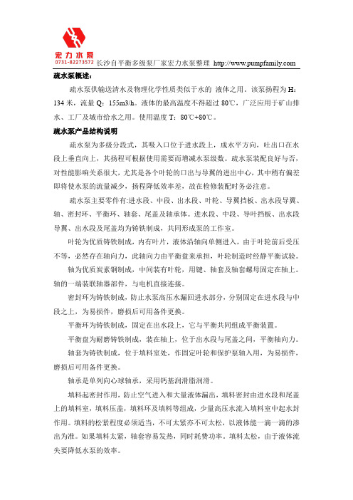
长沙自平衡多级泵厂家宏力水泵整理 疏水泵概述:疏水泵供输送清水及物理化学性质类似于水的液体之用。
该泵扬程为H:134米,流量Q:155m3/h。
液体的最高温度不得超过80℃,广泛应用于矿山排水、工厂及城市给水之用。
使用温度T:80℃+80℃。
疏水泵产品结构说明疏水泵为多级分段式,其吸入口位于进水段上,成水平方向,吐出口在水段上垂直向上,其扬程可根据使用需要而增减水泵级数。
疏水泵装配良好与否,对性能影响关系很大,尤其是各个叶轮的口出与导翼的进出中心,其中稍有偏差即将使水泵的流量减少,扬程降低效率差,故在检修装配时务必注意。
疏水泵主要零件有:进水段、中段、出水段、叶轮、导翼挡板、出水段导翼、轴、密封环、平衡环、轴套、尾盖及轴承体。
进水段、中段、导叶挡板、出水段导翼、出水段及尾盖均为铸铁制成,共同形成泵的工作室。
叶轮为优质铸铁制成,内有叶片,液体沿轴向单侧进入,由于叶轮前后受压不等,必然存在轴向力,此轴向力由平衡盘来承担,叶轮制造时经静平衡试验。
轴为优质炭素钢制成,中间装有叶轮,用键、轴套及轴套螺母固定在轴上。
轴的一端装联轴器部件,与电机直接连接。
密封环为铸铁制成,防止水泵高压水漏回进水部分,分别固定在进水段与中段之上,为易损件,磨损后可用备件更换。
平衡环为铸铁制成,固定在出水段上,它与平衡共同组成平衡装置。
平衡盘为耐磨铸铁制成,装在轴上,位于出水段与尾盖之间,平衡轴向力。
轴套为铸铁制成,位于填料室处,作固定叶轮和保护泵轴入用,为易损件,磨损后可用备件更换。
轴承是单列向心球轴承,采用钙基润滑脂润滑。
填料起密封作用,防止空气进入和大量液体漏出,填料密封由进水段和尾盖上的填料室,填料压盖,填料环及填料等组成,少量高压水流入填料室中起水封作用。
填料的松紧程度必须适当,不可太紧亦不可太松,以液体能一滴一滴的渗出为准。
如果填料太紧,轴套容易发热,同时耗费功率。
填料太松,由于液体流失要降低水泵的效率。
- 1、下载文档前请自行甄别文档内容的完整性,平台不提供额外的编辑、内容补充、找答案等附加服务。
- 2、"仅部分预览"的文档,不可在线预览部分如存在完整性等问题,可反馈申请退款(可完整预览的文档不适用该条件!)。
- 3、如文档侵犯您的权益,请联系客服反馈,我们会尽快为您处理(人工客服工作时间:9:00-18:30)。
扬程 H m
转速 n r/min
效率η %
功率 P(kW) 轴功率 电机功率
汽蚀余量 NPSHr m
-2-
长沙市精工特种工业泵厂
CHANGSHA JINGONG SPECIAL KIND PUMP FACTORY
我们的质量信誉,是您最佳的选择。
更多信息与服务请访问网站
CHANGSHA JINGONG SPECIAL KIND PUMP FACTORY
NW
2006 . 05 NO . 01
我们的质量信誉,是您最佳的选择
目
录
概述......................................................................................................................... 1 型号意义................................................................................................................ 1 结构图 .................................................................................................................... 1 性能参数表 ........................................................................................................... 2
结构图
-1-Βιβλιοθήκη 我们的质量信誉,是您最佳的选择
性能参数表
流量 Q 型 号 m /h
80NW-43×4 36 80NW-36-57×3 100NW-65×2 36 100NW-36-44×3 125NW-65×2 57 125NW-57-44×3 150NW-90×2 134 150NW-134-60×3 150NW-156 150NW-50-58×4 150NW-105-77×3 69 50 105 156 230 230 2970 2950 2980 64 62 70 45.8 50.5 93.9 55 75 110 2 2 2 180 2980 68 96.5 125 2 130 2930 65 31 37 1.5 130 2930 55 23.2 30 1.5 170 2950 60 27.8 37 2
-1-
我们的质量信誉,是您最佳的选择
概
述
NW 型低加疏水泵,用于 125MW~300MW 电厂输送低压加热器疏水,介质温度除 150NW-90X2 型号≤130℃,其余型号都为≤120℃。该系列泵汽蚀性能好,适用于低 NPSH 工况的工作条件。
型号意义
100NW-65×2 100--泵入口直径(mm) NW-卧式疏水泵 65-泵设计点的单级扬程(m) 2-泵的级数(即叶轮轮数)。