MB84101KAN中文资料
千兆网卡详细资料大全
千兆网卡详细资料大全
千兆太网卡是以单位面积时间内,数据流量达到1000兆(约为1G)速度的网路适配卡。
1000Mbit/s网卡也称为千兆乙太网网卡,是根据网速从10M/100M/1000M自适应的网卡,最大传输速度能达到1000Mbit 秒。
千兆乙太网网卡多用于伺服器,以便提供伺服器与交换机之间的高速连线,提高网路主干系统的回响速度。
千兆网卡是一款32-bit PCI汇流排接口标准的10/100/1000Mbit/s网卡,符合10Base-T,100Base-TX,1000Base-T网路标准。
支持32位PCI数据汇流排,传输数据无需占用CPU时间,可以不通过CPU直接与记忆体进行数据交换,从而减轻主机负载。
采用RJ-45接口,使用双绞线接入,实现方便、快捷、简单、可靠的连线。
目前由于数据量的增大和价格的调整,很多普通用户也开始使用千兆乙太网网卡,大有流行的趋势。
WYI350-SFP光纤网卡注意,由于千兆乙太网物理层的实现与10M/100M不同,使用的双绞线需要将四对线都连线上。
制作电缆时需要使用超五类线。
Moxa UC-8410A 系列 IIoT 閘道说明书

UC-8410A系列Arm Cortex-A7雙核心1GHz IIoT閘道,具有使用無線模組的1個擴充插槽、3個LAN連接埠、8個串列埠、4個DI、4個DO特色與優點•Freescale LS1021A Cortex-A71Ghz雙核心處理器•1個GB DDR3SDRAM•8個RS-232/422/485串列埠•3個10/100/1000Mbps乙太網路連接埠•支援無線功能的PCIe迷你插槽•2台USB2.0主機,用於大量儲存裝置•壁掛安裝•堅固的無風扇設計•提供-40至75°C寬溫度型號•Moxa工業Linux,提供10年超長期間支援認證簡介UC-8410A系列嵌入式電腦支援極為豐富的通訊介面,包括8個RS-232/422/485串列埠、3個乙太網路連接埠、1個用於無線模組的PCIe迷你插槽、4個數位輸入通道、4個數位輸出通道、1個mSATA插槽以及2台USB2.0主機。
UC-8410A電腦使用Freescale Cortex-A7雙核心1GHz RISC CPU。
這款功能強大的運算引擎可支援多個實用的通訊功能,不會有產生過熱的情況。
內建的8GB eMMC卡以及1GB DDR3SDRAM可提供足夠記憶體,讓您執行您的應用程式軟體,同時mSATA插槽可讓您靈活地新增額外的資料儲存空間。
UC-8410A電腦配備有各式通訊介面,包括串列埠、乙太網路連接埠、無線通訊插槽,以及數位輸入/輸出通道,使其成為需要網路和裝置通訊的工業應用的理想通訊平台。
UC-8410A系列已配備預先安裝的Linux Debian8,為軟體程式開發提供開放軟體作業系統。
這樣的設計也使得UC-8410A電腦成為工業應用中理想的解決方案,但是無需付出高額成本與過多努力。
除了UC-8410A這款標準型號外,亦提供可適應嚴苛工業環境,可在-40至75°C操作的寬溫度型號。
外觀前視圖後視圖左視圖規格ComputerCPU Armv7Cortex-A7dual-core1GHz System Memory Pre-installed1GB DDR3LStorage Pre-installed8GB eMMCPre-installed OS Linux Debian8(kernel4.4)Moxa Industrial Linux(Debian9,Kernel4.4)Storage Slot SD slots x1mSATA slots x1,internal mini-PCIe socketComputer InterfaceEthernet Ports Auto-sensing10/100/1000Mbps ports(RJ45connector)x3USB2.0USB2.0hosts x2,type-A connectorsDigital Input DIs x4Digital Output DOs x4Expansion Slots UC-8410A-LX Series:1Cellular Antenna Connector UC-8410A-LX Series:2Number of SIMs UC-8410A-LX Series:1SIM Format UC-8410A-LX Series:MiniConsole Port1x4-pin header to DB9console portSerial Ports RS-232/422/485ports x8,software-selectable(RJ45)Digital InputsChannel-to-Channel Isolation3000VDCConnector Screw-fastened Euroblock terminalDry Contact On:short to GNDOff:openSensor Type Dry contactWet contact(NPN or PNP)Wet Contact(DI to COM)On:10to30VDCOff:0to3VDCDigital OutputsConnector Screw-fastened Euroblock terminalCurrent Rating200mA per channelI/O Type SinkVoltage Open-drain to30VDCLED IndicatorsSystem Power x1System Ready x1Storage x1Programmable x10LAN2per port(10/100/1000Mbps)Serial2per port(Tx,Rx)Serial InterfaceBaudrate50bps to115.2kbpsFlow Control RTS/CTS,XON/XOFF,ADDC®(automatic data direction control)for RS-485,RTS Toggle(RS-232only)Parity None,Even,Odd,Space,MarkData Bits5,6,7,8Stop Bits1,1.5,2Serial SignalsRS-232TxD,RxD,RTS,CTS,DTR,DSR,DCD,GNDRS-422Tx+,Tx-,Rx+,Rx-,GNDRS-485-2w Data+,Data-,GNDRS-485-4w Tx+,Tx-,Rx+,Rx-,GNDPower ParametersPower Connector Terminal block(for DC models)Input Current 1.57A@12VAC max.Input Voltage12to48VDCPower Consumption19W(max.)Physical CharacteristicsHousing MetalIP Rating IP30Dimensions200x120x48.6mm(7.87x4.72x1.91in)Weight1,000g(2.21lb)Installation Wall mounting(standard)Environmental LimitsOperating Temperature Standard Models:-10to60°C(14to140°F)Wide Temp.Models:-40to75°C(-40to167°F)Wide Temp.Models with LTE/Wi-Fi:-40to70°C(-40to158°F) Storage Temperature(package included)Standard Models:-20to75°C(-4to167°F)Wide Temp.Models:-40to85°C(-40to185°F)Ambient Relative Humidity5to95%(non-condensing)Standards and CertificationsEMC EN55032/35EMI CISPR32,FCC Part15B Class AEMS IEC61000-4-2ESD:Contact:4kV;Air:8kVIEC61000-4-3RS:80MHz to1GHz:3V/mIEC61000-4-4EFT:Power:0.5kV;Signal:0.5kVIEC61000-4-5Surge:Power:0.5kV;Signal:1kVIEC61000-4-6CS:3VIEC61000-4-8PFMFSafety UL/IEC60950-1&62368-1Shock IEC60068-2-27Vibration IEC60068-2-64DeclarationGreen Product RoHS,CRoHS,WEEEWarrantyWarranty Period5years Details See /tw/warrantyPackage ContentsDevice1x UC-8410A Series computer Installation Kit 1x terminal block,3-pin1x wall-mounting kitCable 1x 4-pin header to DB9console cable1x terminal block to power jack converterDocumentation1x quick installation guide1x warranty card 尺寸訂購資訊Model Name CPUOS mPCIe Slot for Wireless Module SIM Slots Operating Temp.UC-8410A-LX Armv7Cortex-A7dual-core 1GHzDebian 8P 1-10to 60°C UC-8410A-LX (deb9)Armv7Cortex-A7dual-core 1GHzMoxa Industrial Linux (Debian 9)P 1-10to 60°C UC-8410A-T-LX Armv7Cortex-A7dual-core 1GHzDebian 8P 1-40to 75°C -40to 70°C (with Wi-Fi)UC-8410A-T-LX (deb9)Armv7Cortex-A7dual-core 1GHzMoxa Industrial Linux (Debian 9)P 1-40to 75°C -40to 70°C (with LTE/Wi-Fi)UC-8410A-NW-LX Armv7Cortex-A7dual-core 1GHz Debian 8––-10to 60°CUC-8410A-NW-LX(deb9)Armv7Cortex-A7dual-core1GHzMoxa Industrial Linux(Debian9)––-10to60°CUC-8410A-NW-T-LX Armv7Cortex-A7dual-core1GHzDebian8––-40to75°CUC-8410A-NW-T-LX(deb9)Armv7Cortex-A7dual-core1GHzMoxa Industrial Linux(Debian9)––-40to75°C配件(選購)AntennasANT-WDB-ARM-02 2.4/5GHz,omni-directional rubber duck antenna,2dBi,RP-SMA(male)ANT-LTE-OSM-03-3m BK700-2700MHz,multi-band antenna,specifically designed for2G,3G,and4G applications,3m cable ANT-LTE-OSM-06-3m BK MIMO Multiband antenna with screw-fastened mounting option for700-2700/2400-2500/5150-5850MHzfrequenciesANT-LTE-ASM-04BK704-960/1710-2620MHz,LTE omni-directional stick antenna,4.5dBiANT-LTE-ASM-05BK704-960/1710-2620MHz,LTE stick antenna,5dBiCablesCBL-F9DPF1x4-BK-100Console cable with4-pin connector,1mCellular Wireless ModulesUC-8410A LTE-CAT4-EU Telit LE910C4-EU LTE Cat.4mini card with2M2.5screws for the EMEA region,compatible with UC-8410A hardware rev.2.1.0and higherUC-8410A LTE-CAT4-AP Telit LE910C4-AP LTE Cat.4mini card with2M2.5screws for the APAC region,compatible with UC-8410A hardware rev.2.1.0and higherWi-Fi Wireless ModulesWi-Fi-BGN(252NI)Wi-Fi module,2antennas with cable and connector,2black screws,2lock washers,2nuts,1thermalpadDIN-Rail Mounting KitsUC-8410A DIN-rail Kit DIN-rail kit with6M3screws(also included in the UC-8410A Series package)Power AdaptersPWR-24250-DT-S1Power adapter,90to264VAC,24VDC,2.5A DC loadPower CordsPWC-C13CN-3B-183Power cord with three-prong China(CN)plug,1.83mPWC-C13AU-3B-183Power cord with Australian(AU)plug,1.83mPWC-C13JP-3B-183Power cord with Japan(JP)plug,7A/125V,1.83mPWC-C13UK-3B-183Power cord with United Kingdom(UK)plug,1.83mPWC-C13US-3B-183Power cord with United States(US)plug,1.83mPWC-C13EU-3B-183Power cord with Continental Europe(EU)plug,1.83m©Moxa Inc.版權所有.2021年7月27日更新。
M841 IMI
(与GILFLO配用的)M841型通用流量演算器操作说明书(V e r 1.4)目 录1. 特点 (1)2. 用途 (2)3. 主要技术数据 (2)4. 流量运算处理功能 (4)5. 主要画面及操作 (6)6. 功能与使用 (24)7. 安装与接线 (34)8. 仪表的成套性 (35)9. 订货须知 (35)10. 附录蒸汽流量的测量使 用 须 知本仪表在出厂前,已经过严格的检查,用户收到仪表后,请检查外观,确认是否有损坏的地方,同时还应检查标准附件是否齐全。
在使用前,为了达到、充分发挥M841型流量演算器的功能,作为准备工作,首先应该充分理解M841型流量演算器所具备的功能,因此仔细阅读本使用说明书是非常重要的,其次是决定与系统相适应的各个设定数据,并记入数据记录单上。
上述工作是不可缺少的。
1. 特点z与GILFLO 配合组成高精度流量测量系统。
z适用于蒸汽、气体和液体。
z根据温度、压力值自动判断蒸汽处于过热或饱和状态,并分别查表获得密度值。
z自动进行密度补偿、温度补偿、雷诺数补偿和可膨胀性系数补偿。
z带小流量计费、停汽判断、超计划耗用计费、断电记录、无纸记录功能,满足贸易结算计量需要。
z 能自动保存65536组最新的历史数据,保存间隔时间可设置。
z 能自绘制流量、温度、压力等历史曲线,坐标始端和终端可设置。
z 有流量输入信号阻尼功能、仿真功能、蒸汽质量流量和热量计量功能。
z 实时时钟和定时自动抄表功能、打印功能,为计量管理带来方便。
z 能与上位计算机进行数据通讯,组成能源计量网络系统。
z可提供变送器 +24V DC 、+12V DC 供电电源(有短路保护功能),以简化系统、节省投资。
简单的容错功能:温度、压力补偿测量信号异常时,用对应的手动设定值进行补偿运算。
z 流量再发送输出更新周期≤0.5秒,能满足自动调节需要。
z 丰富的自诊断功能使仪表更易使用和维护。
z 密码设定可防止未经授权的人员改变已设定的数据。
M841 流量积算仪
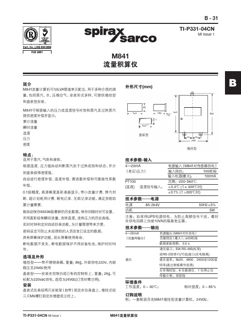
B - 31M841流量积算仪TI-P331-04CN MI Issue 1M841流量积算仪TI-P331-04CN MI Issue 1简介M841流量计算机可与ILVA 管道单元配合,用于多种介质的测量,包括蒸汽,水,压缩空气。
安装形式多样,可提供墙挂型和盘装型安装。
M841可根据输入的压力或温度信号对饱和蒸汽及过热蒸汽提供密度补偿并显示:累计流量瞬时流量温度压力密度特点:适用于蒸汽、气体和液体。
根据温度、压力值自动判断蒸汽处于过热或饱和状态,并分别查表获得密度值。
自动进行密度补偿、温度补偿、雷诺数补偿和可膨胀性系数补偿。
0.1级精度,高清晰度真彩液晶显示,带小流量计费、停汽判断、超计划耗用计费、断电记录、无纸记录功能,满足贸易结算计量需要。
能自动保存65536组最新的历史数据,保存间隔时间可设置。
并用真彩绘制瞬间流量,流体温度,流体压力的历史曲线。
实时时钟和定时自动抄表功能,为计量管理带来方便。
密码设定可防止未经授权的人员改变已设定的数据。
具有屏幕保护功能,延长屏幕使用寿命。
断电数据不丢失。
断电数据保护不用后备电池,保护时间10年。
选项及外形墙挂型——带不锈钢表箱,重量:8kg ,外部供电220v ,内部稳压至24vdc 使用盘装型——安装在控制台或已有的控制柜上。
重量:2kg ,可标配为220vac 供电,选项为24Vdc(订货时需注明)。
安装盘装式仪表经两只安装架(自带)固定在仪表盘上,墙挂式经三只M6螺钉固定在墙壁或立柱上。
外形尺寸(mm)4—20mA 有源输入(M841对传感器供电)(差压\压力) 输入阻抗: 100欧姆 输入电源(最大): 100mAPT100 范围:-200-560℃(温度) 温度信号输入: ±0.3℃ ( t ≤ 300℃时) ±0.1% ( t >300℃时)电源 85-264V 50Hz ±5%功耗 5W 技术参数-输入技术参数——电源注意:如采用UPS 电源供电,为防止高频信号干扰,最好在供电回路上加装10VA 的隔离变压器。
MB1说明书带变频参数表资料
目录第一章简要介绍1.1前言----------------------------------------------------------------------3 1.2 功能简介------------------------------------------------------------------3 1.2.1 基本功能 ---------------------------------------------------------------3 1.2.2 特殊功能 ---------------------------------------------------------------4 1.2.3 安全保护功能 -----------------------------------------------------------4 第二章系统介绍2.1.1 主控微机输入接线端子(变频电梯)----------------------------------------6 2.1.2 主控微机输出接线端子(变频电梯)----------------------------------------7 2.1.3 主控微机输入接线端子(双速电梯)----------------------------------------8 2.1.4 主控微机输出接线端子(双速电梯)---------------------------------------10 2.1.5 主控微机呼梯端子-------------------------------------------------------11 2.1.5.1呼梯按钮开关接线端子--------------------------------------------------11 2.1.5.2呼梯按钮灯接线端子---------------------------------------------------12 第三章系统参数菜单3.1液晶显示屏及按键功能介绍-------------------------------------------------19 3.2主菜单-------------------------------------------------------------------19 3.2.1 CALL(召梯指令)菜单---------------------------------------------------20 3.2.2 TIME(定时计数)菜单---------------------------------------------------21 3.2.3 STATION(设定层站)菜单------------------------------------------------26 3.2.4 I/O(输入输出点)菜单--------------------------------------------------28 3.2.5 SYSTEM(设置系统)菜单-------------------------------------------------33 3.2.6 DOORS(门机系统)菜单 -------------------------------------------------34 3.2.7 ERROR(故障记录)菜单--------------------------------------------------34 3.2.8 PASSWORD(设置密码)菜单-------------------------------------------------35 3.2.9 井道数据菜单-----------------------------------------------------------41 3.3 速度组合表---------------------------------------------------------------44第四章安装及调试4.1 减速距离的确定 ----------------------------------------------------------46 4.2 试运行慢车输入信号-------------------------------------------------------46 4.3 试运行快车输入信号要求---------------------------------------------------46 4.4 井道自学习方法-----------------------------------------------------------46 第五章故障说明及处理方法---------------------------------------------------------48 附表1:安川616G5变频器参数表-------------------------------------50附表2:安川G7变频器参数表----------------------------------------56 附表3:富士G11UD变频器参数表------------------------------------62 附表4:富士5000VG7S变频器参数表---------------------------------67第一章简要介绍1.1 前言LIFTCON-MB1并行电梯控制微机是一款高性能低价格电梯控制系统,是以可靠、低价功能全、易维护、易使用、美观为设计思想。
AMT8410中文资料
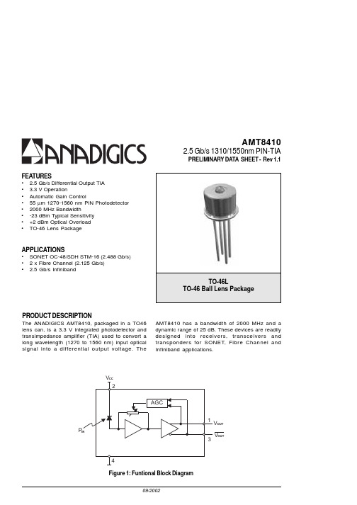
AMT84102.5 Gb/s 1310/1550nm PIN-TIAPRELIMINARY DATA SHEET - Rev 1.1FEATURES• 2.5 Gb/s Differential Output TIA • 3.3 V Operation•Automatic Gain Control•55 µm 1270-1560 nm PIN Photodetector •2000 MHz Bandwidth•-23 dBm Typical Sensitivity •+2 dBm Optical Overload •TO-46 Lens PackageAPPLICATIONS•SONET OC-48/SDH STM-16 (2.488 Gb/s)• 2 x Fibre Channel (2.125 Gb/s)•2.5 Gb/s InfinibandPRODUCT DESCRIPTIONThe ANADIGICS AMT8410, packaged in a TO46lens can, is a 3.3 V integrated photodetector and transimpedance amplifier (TIA) used to convert a long wavelength (1270 to 1560 nm) input optical signal into a differential output voltage. TheAMT8410 has a bandwidth of 2000 MHz and a dynamic range of 25 dB. These devices are readily designed into receivers, transceivers and transponders for SONET, Fibre Channel and Infiniband applications.Figure 1: Funtional Block DiagramAMT84101Figure 2: T46L Pinout (Bottom View)Table 1: Pin DescriptionAMT8410ELECTRICAL CHARACTERISTICSTable 2: Absolute Maximum Ratings Stresses in excess of the absolute ratings may cause permanent damage. Functional operation is not implied under these conditions. Exposure to absolute ratings for extended periods of time may adversely affect reliability.V C C V 0.6P N I mB d 4+T SC°521o t C °56-.p m e T e g a r o t STable 3: Electrical Specifications(1)Measured at -17 dBm optical input power with output connected into R L = 100 Ω(differential).(2)Measured at 10-10 BER with a 223-1 PRBS at 2.5 Gb/s.(3)Measured with a 223-1 PRBS at 2.5Gb/s, an input optical power of -17dBm andR L = 100 Ω (differential).(4)Measured with a 223-1 PRBS at 2.5Gb/s, an input optical power of -3dBm andR L = 100 Ω (differential).(5)6σ about the center eye crossing.AMT8410PERFORMANCE DATAFigure 7:Differential Responsivity vs.CaseTemperature102030405060708090Case Temperature (C)D i f f e r e n t i a l R e s p o n s i v i t y (V /W )102030405060708090Case Tem perature (C)S e n s i t i v i t y (d B m )Figure 8:Sensitivity vs.CaseTemperature40.045.050.055.060.065.070.075.080.0102030405060708090Case Temperature (C)S u p p l y C u r r e n t (m A )P i n =-17d B mFigure 5:Supply Current vs.Case TemperatureFigure 6:Bandwidth vs.CaseTemperature1600170018001900200021002200230024000102030405060708090Case Temperature (C)B a n d w i d t h (M H z )Figure 3:Eye Diagram with an Optical InputPower of -23dBm100ps/Div.5mV/Div.AMT8410Figure 9: Test Setup for Frequency MeasurementsBERTFigure 11: Test Setup for Eye MeasurementsAMT8410V OUTV OUTFigure 12: DUT Test Fixture SchematicAMT8410 PACKAGE OUTLINEFigure 13: T46L Package Outline DiagramAMT8410ORDERING INFORMATIONANADIGICS, Inc.141 Mount Bethel RoadWarren, New Jersey 07059, U.S.A.Tel: +1 (908) 668-5000Fax: +1 (908) 668-5132URL: E-mail: Mktg@IMPORTANT NOTICEANADIGICS, Inc. reserves the right to make changes to its products or to discontinue any product at any time without notice. The product specifications contained in Advanced Product Information sheets and Preliminary Data Sheets are subject to change prior to a product’s formal introduction. Information in Data Sheets have been carefully checked and are assumed to be reliable; however, ANADIGICS assumes no responsibilities for inaccuracies. ANADIGICS strongly urges customers to verify that the information they are using is current before placing orders.WARNINGANADIGICS products are not intended for use in life support appliances, devices or systems. Use of an ANADIGICS product in any such application without written consent is prohibited.。
Moxa UC-8410硬件用户手册说明书

UC-8410 Hardware User’s ManualFirst Edition, October 2008/product© 2008 Moxa Inc. All rights reserved.Reproduction without permission is prohibited.UC-8410 Hardware User’s ManualThe hardware described in this manual is furnished under a license agreement and may be used only inaccordance with the terms of that agreement.Copyright NoticeCopyright © 2008 Moxa Inc.All rights reserved.Reproduction without permission is prohibited.TrademarksMOXA is a registered trademark of Moxa Inc.All other trademarks or registered marks in this manual belong to their respective manufacturers.DisclaimerInformation in this document is subject to change without notice and does not represent a commitment on the part of Moxa.Moxa provides this document “as is,” without warranty of any kind, either expressed or implied, including, but not limited to, its particular purpose. Moxa reserves the right to make improvements and/or changes to this manual, or to the products and/or the programs described in this manual, at any time.Information provided in this manual is intended to be accurate and reliable. However, Moxa assumes no responsibility for its use, or for any infringements on the rights of third parties that may result from its use.This product might include unintentional technical or typographical errors. Changes are periodically made to the information herein to correct such errors, and these changes are incorporated into new editions of the publication.Technical Support Contact Information/supportMoxa Americas:Toll-free: 1-888-669-2872 Tel: +1-714-528-6777 Fax: +1-714-528-6778 Moxa China (Shanghai office): Toll-free: 800-820-5036 Tel: +86-21-5258-9955 Fax: +86-10-6872-3958Moxa Europe:Tel: +49-89-3 70 03 99-0 Fax: +49-89-3 70 03 99-99 Moxa Asia-Pacific:Tel: +886-2-8919-1230 Fax: +886-2-8919-1231Table of ContentsChapter 1Introduction..................................................................................................1-1 Overview..................................................................................................................................1-2Package Checklist....................................................................................................................1-2Product Features......................................................................................................................1-2Product Hardware Specifications.............................................................................................1-3 Chapter 2Appearance and Dimensions......................................................................2-1 Appearance..............................................................................................................................2-2Dimensions..............................................................................................................................2-3Hardware Block Diagrams.......................................................................................................2-4LED Indicators.........................................................................................................................2-4Reset Button.............................................................................................................................2-5Real Time Clock......................................................................................................................2-5 Chapter 3Mounting Options........................................................................................3-1 Wall or Cabinet Mounting........................................................................................................3-2DIN-Rail Mounting..................................................................................................................3-3 Chapter 4Hardware Connection Description.............................................................4-1 Wiring Requirements...............................................................................................................4-2Connecting the Power..............................................................................................................4-2Grounding the UC-8410..........................................................................................................4-3Connecting to the Network......................................................................................................4-3Connecting to a Serial Device..................................................................................................4-4Connecting to the Console Port...............................................................................................4-4CompactFlash..........................................................................................................................4-6USB..........................................................................................................................................4-7DI/DO......................................................................................................................................4-7 Appendix A Regulatory Approval Statements..............................................................A-11IntroductionThank you for purchasing the Moxa UC-8410 RISC-based ready-to-run embedded computer.The UC-8410 features 8 RS-232/422/485 serial ports, 3 10/100 Mbps Ethernet ports, 4 digital input and 4 digital output channels, and CompactFlash and USB ports for adding additional memory. All of these features make the UC-8410 ideal for your embedded applications.This manual introduces the hardware of the UC-8410 embedded computers. After a brief introduction of the hardware features, we focus on installing and configuring the hardware.The following topics are covered in this chapter:OverviewPackage ChecklistProduct FeaturesProduct Hardware SpecificationsOverviewThe UC-8410 features 8 RS-232/422/485 serial ports, 3 10/100 Mbps Ethernet ports, 4 digitalinput channels and 4 digital output channels, a CompactFlash slot for flash disk expansion, and 2USB ports for adding additional memory (such as a USB Flash disk).The UC-8410 uses an Intel XScale IXP-435 533 MHz RISC CPU. Unlike the X86 CPU, whichuses a CISC design, the IXP-425’s RISC design architecture and modern semiconductortechnology provide the UC-8410 with a powerful computing engine and communication functions,but without generating a lot of heat. The built-in 16 MB NOR Flash ROM and 256 MB SDRAMgive you enough memory to run your application software directly on the UC-8410. Since the dualLAN ports are built into the IXP-425 CPU, the UC-8410 is good solution for network securityapplications.Package ChecklistAll models of the UC-8410 series are shipped with the following items:y 1 UC-8410 series embedded computery Wall-mounting kity DIN-Rail mounting kity Quick Installation Guidey Document & Software CDy Cross-over Ethernet cabley CBL-RJ45M9-150: 150 cm, 8-pin RJ45 to DB9 male serial port cabley CBL-4PINDB9F-150: 4-pin pin header to DB9 female console port cable, 150 cmy Universal power adaptor (includes terminal block to power jack convertery Product Warranty StatementNOTE: Please notify your sales representative if any of the above items are missing or damaged. Product Featuresy Intel XScale IXP-435 533 MHz processory On-board 256 MB DDR2 SDRAM (max. 512 MB), 16 MB Flash ROM (max. 32 MB)y8 RS-232/422/485 serial portsy 4 digital input and 4 digital output channelsy Three 10/100 Mbps Ethernet portsy USB 2.0 host for mass storage devicesy CompactFlash socket for storage expansiony Ready-to-run Linux platformy DIN-Rail or wall mounting installationy Robust, fanless design1-2Product Hardware SpecificationsComputerCPU: Intel XScale IXP-435 533 MHzOS (pre-installed): LinuxDRAM: Onboard 256 MB DDR2 SDRAM, support DDR2 up to 512 MBFlash: Onboard 16 MB NOR Flash to store OS, suport up to 32 MBOnboard 32 MB NAND flash to store dataStorage Expansion: Full function CompactFlash x 1USB: USB 2.0 full speed x 2 (OHCI)LAN InterfaceEthernet: 10/100 Mbps x 3, RJ45 connectorsMagnetic Isolation1.5 KV built-inProtection:Serial InterfaceNumber of Ports: 8Serial Standards: RS-232/422/485, software-selectableRJ45Connectors: 8-pinSerial Line Protection: 15 KV ESD for all signalsConsole/Debugging Port: RS-232 (TxD, RxD, GND), 4-pin header outputSerial Communication ParametersData Bits: 5, 6, 7, 8Stop Bits: 1, 1.5, 2Parity: None, Even, Odd, Space, MarkFlow Control: RTS/CTS, XON/XOFF, ADDC™ (automatic data direction control) forRS-485Baudrate: 50 bps to 921.6 Kbps (supports non-standard baudrates; see user’smanual for details)Serial SignalsRS-232: TxD, RxD, DTR, DSR, RTS, CTS, DCD, GNDRS-422: TxD+, TxD-, RxD+, RxD-, GNDRS-485-4w: TxD+, TxD-, RxD+, RxD-, GNDRS-485-2w: Data+, Data-, GNDDigital InputInput channels: 4 points, source typeInput Range: 0 to 30 VDCDigital Input Levels: Dry Contacts:Logic level 0: Close to GNDLogic level 1: OpenWet Contacts:Logic level 0: +3V maxLogic level 1: +10 V to +30 V (COM to DI)Digital OutputOutput Channels: 4 points sink type, keep output status after system hot resetOn-state V oltage: 24 VDC nominal, open collector to 30 VOutput Current Rating: Max. 200 mA per channelConnector Type: 10-pin screw terminal block (4 points, COM, GND)LEDsSystem: Power x 1, Ready x 1, Storage x 1, Battery x 1LAN: 10M/100M x 21-3Serial: TxD, RxD (8 of each)Physical CharacteristicsHousing: SECC sheet metal (1 mm)Weight: 850gDimensions: 200 x 36.5 x 120 mm (7.87 x 1.44 x 4.72 in)wallMounting: DIN-Rail,Environmental LimitsOperating Temperature: -10 to 60°C (14 to 140°F)Operating Humidity: 5 to 95% RHStorage Temperature: -20 to 80°C (-4 to 176°F)Anti-vibration: 1G @ IEC-68-2-6, sine wave, 5-500 Hz, 1 Oct./min, 1hr/axisAnti-shock: 5G @ IEC-68-2-27, half sine wave, 30 msPower RequirementsInput V oltage: 12 to 48 VDCPower Consumption: 12V/1280mA; 48V/300mA.Regulatory ApprovalsEMC: CE (EN55022 Class B, EN55024-4-2, EN55024-4-3, EN55024-4-4),FCC (Part 15 Subpart B, Class B)Safety: UL/cUL (UL60950-1), CCC, LVDReliabilityAlert Tools: Built-in buzzer and RTC (real-time clock)Automatic RebootBuilt-in WDT (watchdog timer)Trigger:WarrantyWarranty Period: 5 years/warrantyDetails: See* Please note that the Hardware Specifications apply to the embedded computer unit itself, but not to accessories.1-42 Appearance and DimensionsThe following topics are covered in this chapter:AppearanceDimensionsHardware Block DiagramsLED IndicatorsReset ButtonReal Time ClockAppearanceUC-8410 Rear View10/100 Mbps Ethernet x 312 to 48 VDCLED Indicators(Power, SRAM Battery, Ready, Storage)UC-8410 Top ViewUC-8410 Front View(RS-232/422/485)2-2DimensionsUC-841012mm36.5mm(Unit=mm)2-3Hardware Block DiagramsThe following block diagram shows the layout of the UC-8410’s internal components.RS-232/422/485 x 8LED IndicatorsThe UC-8410 has 14 LED indicators on the top panel. Refer to the following table for informationabout each LED.LED Name Color MeaningGreen Power is on.PowerOff No power input or any other power error.Green System is ready.ReadyOff OS boot up failure or other system initialization error.Yellow (not blinking) CF card inserted.Yellow (blinking) Data is being read or written.StorageOff No CF card inserted.Red Battery is dead or malfunctioning. It could be used off or does not work properly.BatteryOff Battery is normal.Green Data is being sent through the serial port.TX 1-8Off Data is not being transmitted.Yellow Data is being received through the serial port. RX 1-8Off Data is not being received.2-4Reset ButtonThe button labeled Reset returns the UC-8410 to its factory default configuration.Press the Reset button continuously for at least 5 seconds to load the factory defaultconfiguration. After the factory default configuration has been loaded, the system will rebootautomatically. The Ready LED will blink on and off for the first 5 seconds, and then maintain asteady glow once the system has rebooted.We recommend that you only use this function if the software is not working properly and youwant to load factory default settings. To reset an embedded Linux system, always use the softwarereboot command />reboot to protect the integrity of data being transmitted or processed.Real Time ClockThe UC-8410’s real time clock is powered by a lithium battery. We strongly recommend that youdo not replace the lithium battery without help from a qualified Moxa support engineer. If youneed to change the battery, contact the Moxa RMA service team.2-53Mounting OptionsThe following topics are covered in this chapter:Wall or Cabinet MountingDIN-Rail MountingWall or Cabinet MountingThe two metal brackets that come standard with the UC-8410 are used to attach the UC-8410 to awall or the inside of a cabinet. First, use two screws per bracket to attach the brackets to thebottom of the UC-8410 (Fig. A). Next, use two screws per bracket to attach the UC-8410 to a wallor cabinet (Fig. B).Figure A: UC-8410 Embedded Computer—Wall Mounting Brackets (bottom view)Figure B: UC-8410 Embedded Computer—Wall Mounting Brackets (top view)3-2DIN-Rail MountingAn aluminum DIN-Rail attachment plate is included with the product. If you need to reattach theDIN-Rail attachment plate to the UC-8410, make sure the stiff metal spring is situated towards thetop, as shown in the following figures.STEP 1: Insert the top of the DIN-Rail into the slot just below the stiff metal spring. STEP 2: The DIN-Rail attachment unit will snap into place as shown below.To remove the UC-8410 from the DIN-Rail, simply reverse Steps 1 and 2.3-34Hardware Connection DescriptionThis section describes how to connect the UC-8410 to serial devices for first time testing purposes. The following topics are covered in this chapter: 0 ork vice ort Wiring Requirements Connecting the Power Grounding the UC-841 Connecting to the Netw Connecting to a Serial De Connecting to the Console P CompactFlash USBDI/DOWiring RequirementsYou should also observe the following common wiring rules:y Use separate paths to route wiring for power and devices. If power wiring and device wiring paths must cross, make sure the wires are perpendicular at the intersection point.NOTE: Do not run signal or communication wiring and power wiring in the same wire conduit.To avoid interference, wires with different signal characteristics should be routed separately.y You can use the type of signal transmitted through a wire to determine which wires should be kept separate. The rule of thumb is that wiring that shares similar electrical characteristics canbe bundled together.y Keep input wiring and output wiring separate.y Where necessary, we strongly recommend that you label wiring to all devices in the system. Connecting the PowerThe UC-8410 has a 3-pin terminal block for a 12 to 48 VDC power input.The following figures show how the power input interface connects to external power source. Ifthe power is properly supplied, t the Ready LED will illuminate with a solid green color after 30to 60 seconds have passed.4-2Grounding the UC-8410Grounding and wire routing help limit the effects of noise due to electromagnetic interference(EMI). Run the ground connection from the ground screw to the grounding surface prior toconnecting devices.SG: The Shielded Ground (sometimes called Protected Ground) contact is theleft most contact of the 3-pin power terminal block connector whenviewed from the angle shown here. Connect the SG wire to an appropriategrounded metal surface.Connecting to the NetworkConnect one end of the Ethernet cable to one of the UC-8410’s 10/100M Ethernet ports (8-pinRJ45) and the other end of the cable to the Ethernet network. If the cable is properly connected,the UC-8410 will indicate a valid connection to the Ethernet in the following ways:The lower right corner LED indicator maintains a solidgreen color when the cable is properly connected to a100 Mbps Ethernet network. The LED will flash on andoff when Ethernet packets are being transmitted orreceived.The lower left corner LED indicator maintains a solidorange color when the cable is properly connected to a10 Mbps Ethernet network. The LED will flash on andoff when Ethernet packets are being transmitted orreceived.Pin Signal1 ETx+2 ETx-3 ERx+4 ---5 ---6 ERx-7 ---8 ---4-3Connecting to a Serial DeviceUse properly wired serial cables to connect the UC-8410 to serial devices. The UC-8410’s serial ports (P1 to P8) use 8-pin RJ45 connectors. The ports can be configured by software for RS-232, RS-422, or 2-wire RS-485. The precise pin assignments are shown in the following table:PinRS-232RS-422/RS-485-4wRS-485-2w1 DSR ------2 RTS TXD+---3 GND GND GND4 TXD TXD----5 RXD RXD+Data+6 DCD RXD-Data-7 CTS ------8 DTR --- ---Connecting to the Console PortThe UC-8410’s console port is a 4-pin pin header RS-232 port. Refer to the following figure forconsole port cable pin assignments.Serial console Port&PinoutsSerial Console CablePin Signal1 TxD2 RxD3 NC4 GND4-4The console port is located blow the CF card socket. Use a screwdriver to remove the two screws holding the cover to the embedded computer’s housing.Refer to the following figure for the location of the console port.4-5CompactFlashThe UC-8410 provides one CompactFlash slot that supports CompactFlash type I/II cardexpansion. Currently, Moxa provides a CompactFlash card for storage expansion. Be sure ofpower off the computer before inserting or removing the CompactFlash card.See the following description for CompactFlash card installation instructions.The CF cover is located on the back of the UC-8410. Use a screwdriver to remove the cover andaccess the slot. See the following figure for the locations of the CF socket.4-6If you need device drivers for other kinds of mass storage cards, contact Moxa for information onhow to initiate a cooperative development project.USBThe UC-8410 provides two USB 2.0 hosts. The USB hosts now support adding USB storagedevices.DI/DOThe UC-8410 support a 4-ch digital input and 4-ch digitaloutput. The 8 digital input channels and 8 digital outputchannels use separate terminal blocks.4-7A Regulatory Approval StatementsThis device compli conditions: (1) This es with part 15 of the FCC Rules. Operation is subject to the following two device may not cause harmful interference, and (2) this device must accept any interference received, including interference that may cause undesired operation.。
不锈钢气源处理单元滤器系统说明书

不锈钢气源处理单元气源处理单元不锈钢警告,销售条件!ᅠ ᅠ警告本样本所述的产品和/或系统出现故障或选择不当或使用不当或相关物品可能导致死亡、人身伤害和财产损失。
本文件及其他信息由派克汉尼汾公司、其子公司及授权分销商提供产品和/或系统选项,供具有技术专长的用户进一步研究。
重要的是要分析一切你的应用场合的各个方面,包括任何失败的后果,并检查在当前产品样本有关产品或系统的信息。
由于这些产品或系统的操作条件和应用的多样性用户通过自己的分析和测试,全权负责产品和系统的最终选择能够满足应用场合的所有性能、安全和警告要求。
本样本中所述的产品,包括但不限于产品特性、规格、设计、可用性和价格,如有更改,派克汉尼汾公司及其附属公司可随时更改,恕不另行通知。
销售条件本样本中的产品由派克汉尼汾及分支机构,及授权经销商销售。
所有派克输入的销售合同,将遵守派克的销售标准条款。
(可提供复印件)内容气源处理单元不锈钢产品选型表 (1)空气过滤器微型PF504 .................................................................................................................................................2-3 标准型PF10 ..............................................................................................................................................4-5空气聚结式过滤器微型PF501 .................................................................................................................................................6-7 标准型PF11 ..............................................................................................................................................8-9空气减压阀微型PR354, PR364 ...............................................................................................................................10-11 标准型PR10, PR11 ...............................................................................................................................12-13空气过滤 / 减压阀微型PB548, PB558 ...............................................................................................................................14-15 标准型PB11, PB12 ...............................................................................................................................16-17 标准不锈钢过滤调压阀-主推产品....................................................................................................18-19油雾器标准型PL10 ...........................................................................................................................................20-21系列接口调压范围PSIG 页1/41/22560125250减压阀PR354X –标准标准标准—10-11PR364X –标准标准标准—PR10–X —标准标准可选12-13PR11–X—标准标准可选系列接口杯子杯子容量过滤精度(微米)调压范围PSIG 页1/41/2520402560125250过滤器/减压阀PB548X–316不锈钢 1 oz.可选标准—可选可选标准—14-15PB558X –316不锈钢1 oz.可选标准—可选 可选 标准—PB11–X 316不锈钢 4 oz.可选—标准—可选标准可选16-19PB12X X 316不锈钢 4 oz.可选—标准—可选标准可选油雾器PL10–X316不锈钢4 oz.20-21产品选型表基本单元系列接口杯子杯子容量过滤精度(微米)页1/41/252040过滤器PF504X–316不锈钢 1 oz.可选标准—2-3PF10–X 316不锈钢 4 oz.可选—标准4-5聚结式过滤器PF501X –316不锈钢 1 oz..3 Micron 6-7PF11–X 316不锈钢 4 oz..3 Micron10-11Remote Auto-Fill Device微型颗粒式过滤器气源处理单元不锈钢PF504系列,1/4接口PF504颗粒式过滤器 - 微型• 不锈钢结构可应对大多数腐蚀性环境• 氟橡胶密封标准• 符合NACE规范MR-01-75/ISO 15156• 1/8"内螺纹排水•1/4"接口(NPT, BSPP)常用型号接口AutomaticDrainManual Drain微型颗粒式过滤器气源处理单元不锈钢PF504系列,1/4接口流量曲线工作原理第一级过滤:空气从入口端进入并流经导流板(A),从而引起涡旋作用。
- 1、下载文档前请自行甄别文档内容的完整性,平台不提供额外的编辑、内容补充、找答案等附加服务。
- 2、"仅部分预览"的文档,不可在线预览部分如存在完整性等问题,可反馈申请退款(可完整预览的文档不适用该条件!)。
- 3、如文档侵犯您的权益,请联系客服反馈,我们会尽快为您处理(人工客服工作时间:9:00-18:30)。
118CG01-JMA/MB SeriesOUTSTANDING CHARACTERISTICSI Miniature sizeI Very high Q at high frequencies I High RF power capabilitiesI Impervious to environmental conditions I Low dissipation factorsI Excellent retrace capability (not applicable for X7R styles)I High temperature stability I Low noiseI Meets Mil-55681 with respect to: Shock, Vibration,Moisture Resistance, Solderability, Barometric Pressure,Temperature Cycling, Immersion and Salt SprayADDITIONAL FEATURESI Packaging optionsI Lot processing data availableMA SERIESFor filtering, coupling and impedance matching in most RF circuits, the MA Series chips and leaded devices offer outstanding performance and reliability with the greatest range of values and configurations. MA Series capacitors can be supplied with military equivalent screening. Please consult our factory.MA Series ceramic fixed capacitors are miniature, highperformance precision components having extremely high Q and high power capabilities from low frequencies to gigahertz ranges. These “low loss” multilayer capacitors are extremely stable with respect to variations in temperature, voltage and frequency.MA Series capacitors are designed for miniature state-of-the-art circuit applications. They are small,easy to apply and have excellent reliability. Units areavailable in ultra-miniature case size 1 (1.4 x 1.4 x 1.4mm) or miniature case size 2 (2.8 x 2.8 x 2.5mm). Standard case size 1 units are available as chips. Standard case size 2 units are available as chips and also in leaded configurations.Clean-room manufacturing technology assures product reliability and automated processing reduces costs and cycle time. Key stages of the operation are monitored and controlled with the latest SPC techniques. Flexibility in design allows the production of non-standard values, while maintaining consistent quality objectives.Please contact the factory for availability of specialconfigurations or high-reliability screening.MA18101JANCUBICA-STD SERIES DIMENSIONAL TERMINATION CAPACITANCE TOLERANCES:A: NO 7”Reel MONOLITHICB-ULTRA AND T.C. CODE CODE:CODE: Expressed *B: ±0.1pF MARKING Plastic HIGH Q 1: P90 Case 10: Chip in picofarads and *C: ±0.25pF B: MARKING Tape 5: COG Case 11: Pellet identified by a three-digit *D: ±0.5pF Cap. Code 7: X7R Case 12: Microstrip number. First two digits F : ±1%& Tol.2: P90 Case 23: Radial Ribbon represent significant G: ±2%Logo if space 6: COG Case 24: Radial Wire figures. Last digit J : ±5%permits 8: X7R Case 25: Axial Ribbonspecifies the number K: ±10%Non XR76: Narrow Axial Ribbon of zeros to follow. For M: ±20%styles only7: Axial Wirevalues below 10pF,Z: +80%, –20%8: Nickel Interfaced Pellet the letter “R” is used 9: Nickel Interfaced Chipas the decimal point *Available and the last digit below 10pf becomes significant.onlyPART NUMBERING SYSTEM – CASE SIZE 1 & CASE SIZE 2SPECIAL LEAD CONFIGURATION FOR FLEX BOARDSNOTE: Targeted for flex circuit boards, the MA22-6 version of the MA22 has an upraised lead configuration. The lead bends when flexing the board after assembly so that minimal stress is placed on the component.MA/MB Series DIMENSIONS120CG01-JMA10 & 50 SERIES, P90 & COG – CASE SIZE 1MA70 SERIES, X7R – CASE SIZE 1MACase Size 1 SeriesCap.Cap.Cap.WVDC *Code pF Tol.0R10.1B1500R20.2“1500R30.3B,C1500R40.4“1500R50.5B,C,D1500R60.6“1500R70.7“1500R80.8“1500R90.9“1501R0 1.0“1501R1 1.1“1501R2 1.2“1501R3 1.3“1501R4 1.4“1501R5 1.5“1501R6 1.6“1501R7 1.7“1501R8 1.8“1501R9 1.9“1502R0 2.0“1502R2 2.2“1502R4 2.4“1502R7 2.7“1503R0 3.0“1503R3 3.3“1503R6 3.6“1503R9 3.9“1504R34.3“150*@ 125°C**Extended Cap Range, COG onlyCap.Cap.Cap.WVDC *Code pF Tol.68068F,G,J,K,M150 75075“150 82082“150 91091“150 101100“150 111**110“50 121**120“50 131**130“50 151**150“50161**160“50 181**180“50 201**200“50 221**220“50 241**240“50 271**270“50 301**300“50 331**330“50 361**360“50 391**390“50 431**430“50 471**470“50 511**510“50 561**560“50 621**620“50 681**680“50 751**750“50 821**820“50 911**910“50 102**1000“50*@ 125°CCap.Cap.Cap.WVDC *Code pF Tol.4R7 4.7B,C,D1505R1 5.1“1505R6 5.6“1506R2 6.2“1506R8 6.8B,C,J,K,M1507R57.5“1508R28.2“1509R19.1“15010010F,G,J,K,M15011011“15012012“15013013“15015015“15016016“15018018“15020020“15022022“15024024“15027027“15030030“15033033“15036036“15039039“15043043“15047047“15051051“15056056“15062062“150*@ 125°CCap.Cap.Cap.WVDC ***Code pF Tol.511510K,M,Z50561560“50621620“50681680“50751750“50821820“50911910“501021000“501121100“501221200“501321300“50***@ 85°CCap.Cap.Cap.WVDC ***Code pF Tol.1521500K,M,Z501621600“501821800“502022000“502222200“502422400“502722700“503023000“503323300“503623600“503923900“50***@ 85°CCap.Cap.Cap.WVDC ***Code pF Tol.4324300K,M,Z50 4724700“50 5125100“50 5625600“50 6226200“50 6826800“50 7527500“50 8228200“50 9129100“50 10310000“50***@ 85°CMA20 & 60 SERIES, P90 & COG – CASE SIZE 2MA80 SERIES, X7R – CASE SIZE 2MA Case Size 2 SeriesCG01-J 121Cap.Cap.Cap.WVDC *Code pF Tol.0R10.1B5000R20.2“5000R30.3B,C5000R40.4“5000R50.5B,C,D5000R60.6“5000R70.7“5000R80.8“5000R90.9“5001R0 1.0“5001R1 1.1“5001R2 1.2“5001R3 1.3“5001R4 1.4“5001R5 1.5“5001R6 1.6“5001R7 1.7“5001R8 1.8“5001R9 1.9“5002R0 2.0“5002R1 2.1“5002R2 2.2“5002R4 2.4“5002R7 2.7“5003R0 3.0“5003R3 3.3“5003R6 3.6“5003R9 3.9“5004R3 4.3“5004R7 4.7“5005R1 5.1“5005R6 5.6“5006R2 6.2“5006R86.8B,C,J,K,M500*@ 125°C**Extended Cap Range, COG onlyCap.Cap.Cap.WVDC **Code pF Tol.5125100K,M,Z1005625600“1006226200“1006826800“1007527500“1008228200“1009129100“10010310000“10011311000“10012312000“10013313000“100**@ 85°CCap.Cap.Cap.WVDC **Code pF Tol.15315000K,M,Z10016316000“10018318000“10020320000“10022322000“10024324000“10027327000“10030330000“10033333000“10036336000“10039339000“100**@ 85°CCap.Cap.Cap.WVDC **Code pF Tol.43343000K,M,Z100 47347000“100 51351000“100 56356000“100 62362000“100 68368000“100 75375000“100 82382000“100 91391000“100 104100000“100**@ 85°CCap.Cap.Cap.WVDC *Code pF Tol.7R57.5“5008R28.2B,C,J,K,M5009R19.1“50010010F ,G,J,K,M50011011“50012012“50013013“50015015“50016016“50018018“50020020“50022022“50024024“50027027“50030030“50033033“50036036“50039039“50043043“50047047“50051051“50056056“50062062“50068068“50075075“50082082“50091091“500101100“500111110“300121120“300131130“300151150“300161160“300181180“300*@ 125°CCap.Cap.Cap.WVDC *Code pF Tol.201200“300221220“200241240F ,G,J,K,M200 271270“200 301300“200 331330“200 361360“200 391390“200 431430“200 471470“200 511510“100 561560“100 621620“100 681680“50 751750“50 821820“50 911910“50 1021000“50 112**1100“50 122**1200“50 132**1300“50 152**1500“50 162**1600“50 182**1800“50 202**2000“50 222**2200“50 242**2400“50 272**2700“50 302**3000“50 332**3300“50 362**3600“50 392**3900“50432**4300“50 472**4700“50 512**5200“50*@ 125°CCAPACITORSNote: Limited capacitance range available in 1Kv; consult factory.MB20 ~ 29 SERIES, P90 ±30 – CASE SIZE 2MB Case Size 2 Series122CG01-JCap.Cap.Cap.WVDC *Code pF Tol.0R40.4B,C 10000R50.5B,C,D10000R60.6“10000R70.7“10000R80.8“10000R90.9“10001R0 1.0“10001R1 1.1“10001R2 1.2“10001R3 1.3“10001R4 1.4“10001R5 1.5“10001R6 1.6“10001R7 1.7“10001R8 1.8“10001R9 1.9“10002R0 2.0“10002R1 2.1“10002R2 2.2“10002R4 2.4“10002R7 2.7“10003R0 3.0“10003R3 3.3“10003R6 3.6“10003R93.9“1000*@ 125°CCap.Cap.Cap.WVDC *Code pF Tol.47047F,G,J,K,M30051051“30056056“30062062“30068068“100 75075“100 82082“100 91091“100 101100“100*@ 125°CCap.Cap.Cap.WVDC *Code pF Tol.4R3 4.3B,C,D10004R7 4.7“10005R1 5.1“10005R6 5.6“10006R2 6.2“10006R8 6.8B,C,J,K,M10007R57.5“10008R28.2“10009R19.1“100010010F,G,J,K,M50011011“50012012“50013013“50015015“50016016“50018018“50020020“50022022“50024024“50027027“50030030“50033033“50036036“50039039“50043043“500*@ 125°CCG01-J 123APPLICATION SPECIFIC CAP ACITORSHIGH FREQUENCY CERAMIC CAP ACITORSMA/MB SeriesSPECIFICATIONSMA/MB 18/28; 0.05% maximumDissipation FactorMA 58/68; 0.15% maximum @ 1.0VRMS (f = 1 MHz)MA 78/88; 2.5% maximum @ 1.0VRMS maximum (f = 1kHz)MB28 Series P90±30ppm/°C, (–55°C to +175°C)MA 18/28 Series P90 ±20ppm/°C, (–55°C to +125°C)Temperature CoefficientMA 58/68 Series; COG (0 ±30ppm/°C, –55°C to +125°C)MA 78/88 Series; ±15% maximum (–55°C to +125°C)MA/MB 18/28 1000K M Ohms at +25°C, 100K M Ohms at +125°C Insulation ResistanceMA 58/68 1000K M Ohms at +25°C, 100K M Ohms at +125°CMA 78/88 100K M Ohms or 1000 M Ohm F min., whichever is less (@ 25°C)10K M Ohms or 100 M Ohms F min., whichever is less (@ 125°C)Dielectric T est Voltage MA/MB 18/28/58/68/78/88, 250% of WVDC for 5 seconds Capacitance DriftMeets or Exceeds MIL-PRF-55681 (Does not apply for MA 78/88)AgingNegligible for MA/MB 18/28/58/68, MA 78/88; 2.5% per decade maximumEnvironmental T estsMIL-STD-202Shock Method 213, Condition J Vibration Method 204, Condition BMoisture ResistanceMethod 106Solderability Method 208Immersion Method 104, Condition B Barometric Pressure Method 105, Condition B Resistance to Soldering HeatMethod 210, Condition B Thermal ShockMethod 107, Condition A Life Method 108, Condition FMarkingStandard MA/MB product is unmarkedELECTRICAL PROPERTIESPACKAGING:Case 1 – 3,000 pcs.Case 2 – 1,000 pcs.Cover tapeEmbossmentEmbossed carrierProperty Value Test Method Resistivity 5 x 10⁵ohm/squareASTM D-257Electrostatic Decay Time 0.01 Sec.ASTM D-257At 50% RH@21°COther packaging options available — Consult FactoryTypical ValuesCAPACITORS。