A performance model for integrated layer processing
performance evaluation理工英语4
performance evaluation理工英语4 Performance EvaluationIntroductionPerformance evaluation is a crucial process in assessing the effectiveness and efficiency of individuals, teams, or organizations. It involves the systematic assessment and measurement of performance against predetermined goals, objectives, and standards. This article aims to explore the concept of performance evaluation, its significance in various contexts, and the different methods used for evaluation.Defining Performance EvaluationPerformance evaluation is defined as the systematic process of assessing and reviewing an individual's or organization's performance in relation to established goals and objectives. It involves analyzing the quality, quantity, and timeliness of work, as well as the overall contribution towards achieving desired outcomes.Significance of Performance EvaluationPerformance evaluation plays a critical role in various contexts, including:1. Employee Performance Evaluation: In organizations, performance evaluation helps assess employees' job performance, identify areas for improvement, and determine reward and promotion opportunities. It provides valuable feedback and helps create a performance-driven culture.2. Team Performance Evaluation: Evaluating team performance is essential for identifying strengths and weaknesses, enhancing collaboration, and optimizing resources. It enables organizations to allocate tasks effectively, promote teamwork, and achieve collective goals.3. Organizational Performance Evaluation: Assessing the overall performance of an organization is essential for strategic planning, decision-making, and performance improvement. It helps identify areas requiring attention and enables organizations to align their objectives with key performance indicators (KPIs).Methods of Performance EvaluationThere are several methods used for performance evaluation, depending on the nature and context of evaluation:1. Rating Scales: This method involves using predefined scales to rate employees' performance against specific criteria. It provides a structured approach and simplifies the evaluation process. However, it can be subjective and may not capture the full extent of performance.2. 360-Degree Feedback: This method involves obtaining feedback from multiple sources, including supervisors, subordinates, peers, and customers. It provides a holistic view of an individual's performance and promotes a comprehensive understanding of strengths and areas for improvement.3. Objective Measurements: Objective measurements involve quantifying performance based on quantifiable data, such as sales figures, production output, or customer satisfaction ratings. This method provides a precise assessment of performance but may not capture qualitative aspects.4. Self-Assessment: Self-assessment encourages individuals to reflect on their performance and identify areas for improvement. It promotes self-awareness, accountability, and personal development. However, it may be biased and influenced by individuals' perceptions.5. Behavioral Observation: This method involves directly observing individuals' behavior in specific work-related situations. It provides valuable insights into work habits, interpersonal skills, and adherence to organizational values. However, it can be time-consuming and may not capture performance in all areas.ConclusionPerformance evaluation is a vital process for assessing and improving individual, team, and organizational performance. It helps organizations align their objectives, motivate employees, and ensure efficient resource allocation. By using appropriate evaluation methods, organizations can drive continuous improvement and achieve long-term success. It is essential for organizations to establish clear evaluation criteria, provide constructive feedback, and support employee development to maximize the benefits of performance evaluation.。
performance evaluation理工英语4 -回复

performance evaluation理工英语4 -回复Performance evaluation is a crucial process for organizations to assess and measure the performance of their employees. It is a systematic and objective review of an individual's job performance, focusing on their accomplishments, strengths, areas of improvement, and goals for the future. In this article, we will explore the steps involved in conducting an effective performance evaluation.Step 1: Establishing clear performance expectationsThe first step in conducting a performance evaluation is to establish clear performance expectations for the employee. This involves setting clear goals and objectives that are specific, measurable, achievable, relevant, and time-bound (SMART). By establishing clear expectations, both the employee and the evaluator have a common understanding of what is expected and can work towards achieving those goals.Step 2: Collecting performance dataOnce the performance expectations are set, the next step is to collect data on the employee's performance. This can be done through various methods, such as self-assessment, supervisorfeedback, peer feedback, customer feedback, and objective performance metrics. Gathering data from multiple sources provides a comprehensive perspective on the employee's performance and reduces bias.Step 3: Conducting a performance review meetingAfter collecting the necessary data, the evaluator conducts a performance review meeting with the employee. This meeting provides an opportunity to discuss the employee's performance, strengths, areas for improvement, and future goals. It is important to approach the meeting with a constructive and non-biased mindset, focusing on providing feedback and guidance rather than criticism.Step 4: Providing constructive feedbackDuring the performance review meeting, the evaluator provides constructive feedback to the employee. This feedback should be specific, accurate, and focused on behavior and results rather than personal traits. The evaluator should highlight the employee's achievements and strengths, while also addressing areas where improvement is needed. It is essential to maintain a balanced approach, recognizing the employee's hard work while alsoencouraging growth and development.Step 5: Developing a performance improvement planIf there are areas for improvement identified during the performance review, it is important to develop a performance improvement plan. This plan outlines specific actions and steps the employee can take to improve their performance in the identified areas. The plan should be collaborative and mutually agreed upon, with clear objectives, timelines, and support mechanisms in place to help the employee succeed.Step 6: Monitoring and reviewing progressAfter the performance improvement plan is implemented, it is crucial to monitor and review the employee's progress regularly. This may involve periodic check-ins, coaching sessions, orfollow-up meetings to track the employee's improvement and provide ongoing support. Regular communication and feedback are essential to ensure that the employee stays on track towards achieving their goals and making necessary improvements.Step 7: Rewarding and recognizing good performanceFinally, it is important to recognize and reward good performance.Acknowledging and appreciating the employee's achievements and efforts boosts morale and motivation. Rewards and recognition can come in various forms, such as salary adjustments, bonuses, promotions, or simply verbal praise and public acknowledgment. This step helps create a positive work environment, encourages continued excellence, and reinforces the value of performance evaluation.In conclusion, conducting a performance evaluation involves several important steps, from establishing clear performance expectations to providing constructive feedback and implementing a performance improvement plan. It is a comprehensive and ongoing process that aims to assess, motivate, and develop employees, ultimately contributing to the overall success of the organization.。
自动化测试系统顶层设计方法论说明书
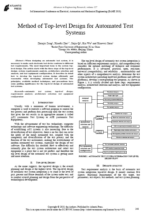
Method of Top-level Design for Automated TestSystemsZhenjie Zeng1, Xiaofei Zhu1,*, Shiju Qi1, Kai Wu2 and Xiaowei Shen11Rocket Force University of Engineering, Xi’an, China2Troops No. 96604, Beijing, China*Corresponding authorAbstract—When designing an automatic test system, it is necessary to make each electronic test device conform to different test requirements. The most important issue is the system top-level design. The article starts with the three steps of the top-level design: system requirements analysis, architecture selection and analysis, and test equipment configuration. It describes in detail how to develop the top-level system design efficiently and reasonably when developing automated test systems. The principles, available method techniques, and precautions have some guiding significance for the top-level design of automated test systems.Keywords—automatic test system; top-level design; requirements analysis; architecture selection; test equipment configurationI.I NTRODUCTIONUsually, with a minimum of human involvement, a computer is used to execute a software program to control the test process and perform data processing until the test system that gives the test results in an appropriate manner is called ATS (Automatic Test System) or ATE (Automatic Test Equipment). .With the advancement of test bus technology, computer technology and software engineering technology, the difficultyof establishing ATS systems is also increasing. Due to the diversification of test objectives, there is no bus that can cover the needs of the entire automated test, coupled with the complexity and diversification of the test process and the function of the test instruments, making the establishment of modern automated test systems, especially the design of test software. The difficulty has doubled. How to effectively and rationally plan the test system architecture and select test equipment is a place that is not yet perfect, and therefore the top level design of the automatic test system is getting more and more attention.II.T OP-LEVEL D ESIGNAs the name suggests, the top-level design is the overall planning and design at the highest level. The top-level design of automatic test system integration is to stand at the level of past, present and future demands of the system under test, and to conduct overall planning and design from the perspective of technological development.The top-level design of automatic test system integration is based on sufficient requirements analysis, and comprehensively considers the optimal matching of technical and economic performances. It is advanced, practical, open, real-time, universal (compatibility), and reliability. , maintainability and other aspects of a comprehensive analysis, determine the test system architecture (including hardware platforms and software platforms), develop a corresponding test program. As shown in Figure 1, it is usually divided into three steps: requirements analysis, architecture selection and analysis, and test equipment configuration.AemandanalysisArchitectureselection andanalysisTest equipmentselection andconfigurationFunctional AnalysisTarget signal typeMeasured parameter definitionTestability analysisTest method analysisInterface bus analysisHardware architecture analysisController selection and analysisHardwareplatformSoftware operating environment analysisOperating system selection and analysisDevelopment platform selection and analysisDatabase selection and analysisTest instrument (module) selectionUTT interface connection designSpecial parameters require processingSoftwareplatformFIGURE I. AUTOMATIC TEST SYSTEM INTEGRATION TOP LEVELDESIGN FLOWIII.D EMAND A NALYSISTest requirement analysis is the basis of automatic test system integration top-level design. It mainly contains five aspects: functional requirements of the test target, test parameters, test objects, test methods, and test system planning.3rd International Conference on Electrical, Automation and Mechanical Engineering (EAME 2018)A.Test Target Functional RequirementsThe different requirements of the test equipment working platform determine the test speed requirements, and also determine the different requirements of the online/offline test; the main control method and logic of the tested equipment determines the difference between the test procedures and methods; the input frequency of the tested equipment, Different parameters, such as amplitude and modulation method, determine the overall requirements for the operating frequency band, small signal level (minimum leakage), and waveform parameters of the automatic test system analog signal source; the output and content of the device under test determines the signal sampling of the automatic test system. The data acquisition method is different; the digital communication interface of the device under test determines that the digital communication interface that the automatic test system should have is different from the protocol; the testability interface of the device under test determines the final test capability and fault diagnosis ability of the automatic test system.B.Test ParametersThe test parameter analysis includes analysis: the form of the measured parameter (electrical or non-electrical, digital or analog, etc.), range and quantity; performance index (measurement accuracy and speed, etc.); the form and range of the excitation signal. In particular, when analyzing requirements for a top-level design of a general-purpose comprehensive automatic test system that is suitable for multiple systems, multiple protocols, and multiple equipment, comprehensive analysis is often required to integrate the test parameters.C.Test ObjectThe test objects vary widely. When analyzing the test objects, a comprehensive analysis must be performed in conjunction with the test system requirements of the test objects. In the face of a specific test object test system or subsystem, the description can use a variety of expressions to give different models of the test system at different levels of simplification, such as language descriptions, graphics, and mathematical formulas. As a simplified description of some test systems, their models merely express their basic characteristics, often ignoring irrelevant details in order to simplify their complexity. For a complex test object test system, a model is inevitably limited by some assumptions in its design and utility. These conditions often have some ambiguity and basically reflect an implicit conceptual idea. Therefore, when analyzing the requirements of a specific test object, it is usually necessary to establish a corresponding test system model.D.Test MethodsAccording to the functional requirements of the test target, a corresponding test method is formulated for the “face-to-face automatic test system” or “object-oriented automatic test system”.. E.Test System PlanningWhen developing an automated test system, it often takes a lot of time to complete the test-assisted tasks such as creating files and programming supporting test software. The test application software development platform can standardize all kinds of test processes and integrate an operating system that is suitable for various test and post-processing functions. It can help us to complete these test auxiliary work; therefore, we use this kind of test platform to conduct various tests. When testing, you can save a lot of time.IV.A RCHITECTURE S ELECTION AND A NALYSIS On the basis of sufficient requirements analysis, determining the architecture of the automated test system is the most critical step in the top-level design. That is how to determine the test plan from the perspective of the top-level design, and select the hardware platform and software platform architecture of the automatic test system, and the most important one is the selection of the test equipment digital communication interface bus.A.System Test Plan SelectionThe system test plan is the overall concept of product testing. It specifies the type of product testing, when (continuous or regular) testing, where (field or workshop, or which maintenance level), testing methods, and test methods used. The types of system test can be divided into: system-wide test and departmental system test, static test and dynamic test, online test and offline test, quantitative test and qualitative test, continuous test and periodic test, etc. The test level can be divided into three levels according to the location: production site, use site, and maintenance base. The test system (equipment) operating methods are generally:According to the use of the operation can be divided into three kinds of automatic, semi-automatic and artificial; according to the general degree of application can be divided into two kinds of special and general equipment; according to the association with the product can be divided into two kinds of BITE and external test equipment.Most of the test methods used in automated testing have so far been modeled on manual tests, from the measurement principles used, the testing techniques used, to the test procedures performed, except that computers were used instead of manual operations. As far as the characteristics and potential of automatic testing are concerned, fundamental reforms of the test plan are needed for future research.B.Selection of Test Equipment Digital CommunicationInterface Bus and ATS StructureThe development of automatic test systems has promoted the continuous emergence of various general-purpose test equipment interface buses and rapid technological advancement: from the early GPIB, CAMAC to the recent VXI, MXI, PCI, PCIe, PXI, PXIe, cPCI, MMS, IEEE1394 ( Firewire), USB, etc. Although technical characteristics are not the same, they are widely used.The structural elements of a modern automated test system are programmable test instruments, test controllers, interconnected standard digital interfaces, and software systems. At present, modern automatic testing has been widely used, and the test objects faced are large, complex, and diversified, making it impossible for an automatic test system based on any kind of bus technology to cover the needs of the entire test object.Multi-bus fusion automatic test system structure shown in Figure 2. It consists of test instruments, DUTs(design under test) and UUT(unit under test) interfaces, test controllers (computers), various general-purpose digital interface buses, and test software. The test controller is interconnected with the test instrument through the digital interface bus, and the device under test is connected to the input/output terminal of the test instrument through the UUT interface. The digital interface bus used may be GPIB, VXI, PXI, LXI, or even an internal computer bus (AT/EISA/PCI), or their convergence. Once the standard digital interface bus architecture used is determined, the automatic test system architecture is basically selected. In an automatic test system, regardless of the interface bus architecture, an external computer or built-in computer system can be selected as the test system controller. The choice of the test system controller should fully consider the optimal matching of technical and economic performance, and choose from real-time, practical, reliable, flexible and convenient.CAT test hostMaster control computerGPIB instrument PC card typeinstrumentVXIinstrumentPXIinstrumentUUT interfaceUUT……FIGURE II. MULTI-BUS FUSION AUTOMATIC TEST SYSTEMSTRUCTUREC.Test Software Platform Mode SelectionIn modern computer-based automated test systems, hardware is the foundation and software is the soul. Test software has increasingly become the main body of ATS, which determines the advanced nature, reliability, practicality, and real-time performance of the entire automated test system.The automatic test software platform mainly refers to the programming language and software support environment involved in the test application software design. It is an integrated software platform such as a computer operating system, a test programming language, a database software, and a program diagnosis software. The key element is Test programming language. Since the automatic test system was popularized and applied, there have been great developments in testing programming languages from low-level to high-level, to the current test application development environment.V.T EST E QUIPMENT C ONFIGURATION After the system structure of the test system is determined, the next task is to synthesize the test contents according to the requirements analysis, and to match the corresponding test equipment according to the test content requirements. There are three types of optional test equipment: general test equipment, special purpose equipment, and test interface adapter.A.Universal Test EquipmentThe universal test equipment includes a main box, a test controller, a main control interface, a zero slot controller, an instrument module, and a desktop instrument. The following factors should be considered when selecting the type of equipment: (1) The higher the degree of equipment automation, the shorter the time for detecting and isolating faults, and the less the manpower consumption, but the cost of test equipment will increase and more protection is needed. (2) Differences in capabilities between the two are to be considered when selecting a BIT (Built-in-Test) and an off-board automatic test equipment. (3) When the BIT is used in conjunction with the off-board automatic test, make full use of the BIT capability of each unit under test. (4) When selecting a dedicated or general-purpose device, it is necessary to consider that the special-purpose device is simple and convenient to use and has high efficiency, but the use range is narrow. (5) The main selection of instrument and equipment is based on the requirements of test parameters, characteristics of the signal to be measured, and range selection. When selecting the instrument module, pay attention to the size of the bus module, power, and number of slots.B.Special Purpose EquipmentWhen the test is not ready for selection, in addition to the above-mentioned common tests, when preparing for the following situations, it may be considered to develop or develop special purpose instrument (module) equipment. When the current product can not meet the test requirements, multiple instruments and equipments are required to complete the measurement together. However, the utilization rate of each instrument is very low or can be accomplished with one instrument. When the price is high and the utilization rate is low, the use of development or development is considered. Special purpose instrument.C.Test Interface Adapter DesignFor different test objects, the extraction and feeding of various test signals requires the design and manufacture of various test interfaces and special fixtures. In the automatic test system, especially the automatic test system assembly of complex electronic equipment, the requirements of the same type but different models and different test objects existuniversally, and often require the test system group to build a relatively universal automatic test platform. Through this platform, different test modules and test methods can be used to quickly and easily complete the automatic test system set-up (configuration) task for different test objects; however, the test interface and the dedicated test module cannot be matched and can only be tested according to the device under test. The test requires the development of a test interface adapter.VI.C ONCLUSIONThis article starts with the three steps of the top-level design: system requirements analysis, architecture selection and analysis, and test equipment configuration. It describes in detail how to perform top-level design efficiently and reasonably when developing automated test systems, and analyzes what the design must follow. Principles, methods, techniques, and precautions have certain guiding significance for the top-level design of automated test systems.R EFERENCES[1]LI Xing-shan, ZUO Yi, SUN Jie. Automatic Test System IntegrationTechnology[M]. Publishing House of Electronics Industry, 2004.[2]QIN Hong-lei, LU Hui et al. Automatic Test System. Beijing: HigherEducation Press, 2007[3]LIU Si-jiu, ZHANG Li-yong. Automatic Test System and VirtualInstrument. Beijing: Publishing House of Electronics Industry, 2009 [4]GU Zhi-yong, TENG Peng, HU Shi-guo, et al. Top-level design of ATSoverall plan for integrated helicopter display systems[J]. Electro-optics and Control, 2008, 15(11):59-62.[5]GU Ya-ping. Research on Top Design of VXI Bus TestingTechnology[J]. Electronic Testing, 1998(8):22-23.。
Giant Integrated Seat Post (ISP) Cutting Guide

Congratulations on your purchase of a Giant Integrated Seatpost (ISP) frame. ISP (FIG. 1) represents the latest achievement in design and engineering, but also requires special attention. While Giant Bicycle engineers use the highest quality materials to form this ISP, you must follow certain guidelines and use proper equipment to attain optimal performance.ISP Cutting InstructionsA proper saddle height brings out the best performance and comfort in your bicycle. To meet the correct saddle height, the integrated seat post might require cutting off at a specific length. Since the cutting of the ISP is a precision task requiring training and experience, only Giant dealers should complete the authorized process.● STEP1.Install the saddle onto the seatpost using the included saddle clamp mechanism.The additional range (20mm) of saddle height adjustment (utilizingthe The final cut length must not exceed the Maximum Cutting Length limits (see seat clamp or structural failure of the ISP.● STEP2.Loosen the saddle clamp bolt and remove the saddle ● STEP3.First, lay your frame flat on a clean surface protecting the finish with a clean soft cloth at points of contact. Insert the seatpost in the Park Tool SG-7.2 Saw Guide to the precise location of the desired cut.Be sure to double-check your measurement.●STEP4.Put the seat tube in a horizontal position. Use the Cutting Guide to guide the hacksaw blade to achieve a straight, perpendicular cut (as per Park Tool's instructions).To avoid fraying thefibers. Use a fine toothsafety equipment, such as glasses,gloves and a dust mask. Make sureTake care when finishingthe cutting process to not splinterthe composite.●STEP5.Carefully sand-down any burrs with fine emery paper.●STEP6.Remove the Cutting Guide from the integrated seatpost. Then, install the saddle onto the seatpost and rechecking the Target Saddle Height.If the SADDLE HEIGHT is still lower than the target (or when you want to fine tune saddle height in the future), you should use the included ISP seat clamp spacers toIf the end of the integrated seat post is not touching the base of the seatAfter adding the appropriate number of ISP spacers, make sure the ISP does not fall below the Minimum Insertion Mark . Otherwise the ISP may break and result in a serious accident.STEP7.Tighten the saddle clamp bolt with a recommended torque to avoid the saddle from Do not grease the integrated seatpost or the inner side of the saddle。
the following section assignments of model -回复

the following section assignments of model -回复The section assignments of the model refer to the specific tasks or responsibilities assigned to different parts or components of the model. These assignments help in ensuring an organized and efficient functioning of the model. In this article, we will provide a step-by-step explanation of each section assignment of the model, elaborating on their importance and how they contribute to the overall operation.1. Data collection and preprocessing:The first assignment deals with collecting relevant data for the model and preparing it for analysis. This involves identifying the sources of data, ensuring its quality and reliability, and converting it into a suitable format for further analysis. Proper data collection and preprocessing are crucial for the accuracy and effectiveness of the model.2. Feature selection and engineering:In this assignment, the focus is on selecting the most relevant features or variables for the model and engineering new features if required. Feature selection helps in reducing the dimensionality of the data and improving the model's efficiency. Feature engineering involves creating new features by combining or transformingexisting ones to capture additional information or patterns.3. Model building and training:The next assignment involves building the actual model using the selected features and training it on the prepared dataset. This step includes selecting the appropriate algorithms and techniques based on the problem at hand and the available data. The model is trained using labeled data to learn the underlying patterns and relationships.4. Model evaluation and validation:Once the model is trained, it needs to be evaluated to assess its performance and validity. This assignment involves various metrics and techniques to evaluate the model's accuracy, precision, recall, and other relevant parameters. Cross-validation techniques are often used to validate the model's generalizability and robustness.5. Model optimization and tuning:In this assignment, the focus is on improving the model's performance by optimizing its parameters and tuning the algorithms used. Different optimization techniques such as grid search or Bayesian optimization can be employed to identify the optimal set of hyperparameters for the model. This step involves experimentation and fine-tuning to achieve the best possible results.6. Model deployment and integration:The penultimate assignment deals with deploying the trained model into a production environment where it can be utilized for real-time predictions or decision-making. This step involves integrating the model with existing systems, creating relevant APIs or interfaces, and ensuring its compatibility and scalability. Continuous monitoring and maintenance are also essential to ensure the model's ongoing performance and accuracy.7. Model interpretation and communication:The final assignment focuses on interpreting and communicating the model's results and findings to stakeholders and decision-makers. This step involves translating complex technical jargon into easily understandable insights and recommendations. Visualization techniques and storytelling methods can be employed to effectively communicate the model's outcomes and implications.In conclusion, the section assignments of the model encompass a series of steps that collectively form a comprehensive approach to data analysis and modeling. Each assignment plays a crucial role in ensuring the model's accuracy, efficiency, and usability. By following these assignments in a systematic manner,organizations can harness the power of data and make informed decisions that drive growth and success.。
伯劳特911 Targa 4产品配置说明书
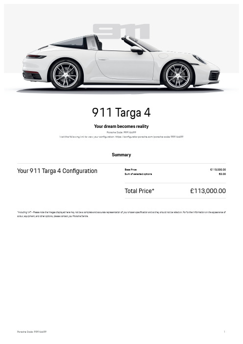
911 Targa 4Your dream becomes realityPorsche Code: PR9X66R9Visit the following link to view your conpguration: htt/s:..conpguratorm/orschemco-./orscheYcode.PR9X66R9SummaryBour 911 Targa 4 Conpguration£ase Price311,0SSSmSS*u- of selected o/tions3SmSSTotal PriceA311,0SSSmSSAincluding VbT Y Please note the i-ages dis/layed here -ay not Fe a co-/lete and accurate re/resentation of your chosen s/ecipcation and so they should not Fe relied onm qor further infor-ation on the a//earance of colour0 eOui/-ent0 and other o/tions0 /lease contact your Porsche Centrem911 Targa 4Exterior Colours & WheelsCategory W/tion W/tion code Price Exterior colours Qhite S23SmSSConvertiFle To/ in Flack1V3SmSS Wheels19Yinch. HSYinch Carrera Qheels46E*tandard UOui/-entInterior Colours & SeatsCategory W/tion W/tion code Price Interior colours & materials£lack leather interior b53SmSS ArraySeats*/orts seats 4Yway28b*tandard UOui/-entExterior OptionsCategory W/tion W/tion code Price ArrayPowertrain & chassis DYs/eed Porsche (o//elku//lung KP()G•1•*tandard UOui/-ent911 Targa 4Standard EquipmentWheelsZ19Yinch. HSYinch Carrera QheelsZ19Yinch. HSYinch Carrera Qheels with H,8.4S MR 19 front tyres and H98.,8 MR HS rear tyresZ Tyre Pressure xonitoring *yste- KTPxGZ Tyre re/air kit with sealing co-/ound and electric air co-/ressorSeatsZ*/orts seats 4YwayPowertrain & chassisZ DYs/eed Porsche (o//elku//lung KP()GZ6Ycylinder FoNer engine with twinYturFo0 dis/lace-ent: ,mS litres0 -aNi-u- /ower out/ut: HD, kQ K,D8 P*G0 -aNi-u- torOue: 48S I-Z DYs/eed Porsche (o//elku//lung KP()G Y DYs/eed dualYclutch trans-ission with -anual control via gearshiL /addles at steering wheelm jncludes an auto-atic -odeZ xcPhersonYfront aNle with antiYroll FarZ xultiYlink rear aNle with antiYroll FarZ4Y/iston0 alu-iniu- pNed -onoFloc Frake cali/ers front and rear0 Frake discs with ,,S -- dia-eter front and rear0 all discs internally vented and crossYdrilled0 Frake cali/ers £lack Z bllYwheel drive with -a/ controlled -ultiY/late clutch Porsche Traction xanage-ent KPTxGZ*PWRT Futton to activate dyna-ic driving settings for engine and trans-issionZ blu-iniu- engine Flock and cylinder headsZ Ulectro-echanical /ower steering with variaFle steering ratio and steering /ulse generatorZ QaterYcooled engine with ther-al -anage-entZ Porsche bctive *us/ension xanage-ent KPb*xGZ*tationary -anage-ent with EW+( functionZ Porsche *taFility xanage-ent KP*xG inclm b£* with eNtended Frake functionsZ H turFochargers0 H intercoolersZ buto start.sto/ functionZ(irect quel jn'ection K(qjGZ VarioCa- Plus variaFle valve ti-ing and liLZ jntegrated dryYsu-/ luFrication with an onYde-and controlled oil /u-/Z Two ,Yway catalytic converters and onYFoard diagnostics for -onitoring e-ission control syste-Z H gasoline /articulate plters K•PqGZ UN/ansion intake -anifoldZ UNhaust syste- with H tuFe tail/i/e tri-s pNed to the Fu-/er Kin stainless steelGZ Ulectrically o/erated /arking FrakeExteriorZ H‘H seater with rear engineZ jntelligent lightweight construction in alu-iniu- and steel co-/ositeZ*ide air intakes at front with active cooling air ’a/s and air FladesZ butoYde/loying rear s/oilerZ Tri- on side skirts in £lackZ RetractaFle door handlesZ xodel designation on rear tri- in +ightsilver911 Targa 4Z zPWR*CEUz lettering integrated in taillight stri/Z Rear lid grille with vertical slats in *ilver KhighYglossGZ qully auto-atic roof syste-0 co-/rising a faFric hood with roof shell and integral -agnesiu- ele-ents0 and a curved0 heataFle rear screen in la-inated safety glassm Roof o/erated when vehicle stationaryZ Qind de’ector in windscreen cowl surroundZ qiNed Targa roll Far with tri- in alu-iniu-0 gills and 7targa¹ logoLights & visionZ+U( -ain headlights including dayti-e running lights with 4Y/oint +U( s/otlightsZ Reading lights0 orientation0 ignition lock0 luggage co-/art-ent0 footwell0 glove co-/art-ent and door lightning all Fuild on +U( technologyZ jllu-inated vanity -irrors in sun visors for driver and /assengerZ+U( auNiliary light units in the front end with /osition lights0 direction indicators and side indicatorsZ Taillight stri/ including integrated /arking lights and rear fogYlightZ buto-atic headlight activation inclm 7Qelco-e Eo-e¹ lightingZ ThreeYdi-ensional +U( taillights inclm reversing light and direction indicators as well as integral third Frake lightsZ UNterior -irrors on door waist rails0 electrically ad'ustaFle and heataFle0 as/herical on driverzs sideZ Qindscreen washer syste- with aero wi/er Flades and washer 'etsZ buto-atically di--ing interior and eNterior -irrors with integrated rain sensorInterior designZ HY®one auto-atic cli-ate control with se/arate te-/erature settings for driver and front /assenger0Z jnstru-ent cluster with central rev counter and two ™Yinch TqT dis/lays0 1Sm9Yinch Centerdis/layZ xultifunctional steering wheel with shiL /addles and -anual heightY and reach ad'ust-entZ qront luggage co-/art-entZ Particle./ollen plter with active carFon plterZ*/orts seats with electric Fackrest angle and seat height ad'ust-ent and -anual ad'ust-ent of fore.aL /ositionZ qullYsi®e airFags KtwoYstageG for driver and front /assengerZ•ear indicator in rev counterZ P() gear changer lever with auto-atic -ode0 -anual gear selection via shiL /addles at the steering wheelZ bscending centre console with storage co-/art-entZ U-Fossed leather on front center seat0 side Folsters and front seat headrestsZ*-oothYpnish leather on steering wheel ri-0 door handles0 door /anel ar-rests and centre console storage co-/art-ent lidZ*torage co-/art-ent in each doorZ Porsche *ide j-/act Protection KPW*jPG0 co-/rising side i-/act /rotection ele-ents in the doors and EeadYThoraN airFag for driver and front /assengerZ•love co-/art-ent KlockaFleG and storage co-/art-ent in each doorZ(ashFoard tri- stri/0 centre console tri- and door /anel tri- stri/s in (ia-ar darksilverZ Two individual cu/holders K1N as inlet in the center console and 1N /assenger sideGZ xounting /oints on /assenger seat for j*WqjX child seat -ounting syste-Z Ungine i--oFiliser with re-ote central locking and alar- syste- with ultrasonic soundYFased interior surveillanceZ•reenYtinted ther-ally insulated glassZ Eeated rear screenZ Eood lining in Flack faFricZ(oor sill guards with -odel designationZ H 5*£YC /orts in center console -ain storage co-/art-ent lid0 socket K1HYvoltG in /assenger footwellZ qloor -atsZ Clothes hooks on seat FackrestsZ*eat heating KfrontGZ RollYover /rotection integrated into pNed Targa roll Far911 Targa 4Comfort & usabilityZ U-ergency call syste- eCallZ Porsche QUT xodeZ Qarn and £rake bssist inclm Pedestrian /rotectionZ)eyless driveZ Parkbssist front and rear including reversing ca-eraZ Ulectric window liLs with oneYtouch o/eration and door seal /rotectionZ Cruise controlZ Re-ote control for central locking syste- and luggage co-/art-ent lid releaseZ Pre/aration for Porsche (ashca-InfotainmentZ(igital radioZ*ound Package Plus0 analogue sound syste-0 D louds/eakers0 18SYwatt total out/ut with integral a-/liper and digital signal /rocessingZ Porsche Co--unication xanage-ent KPCxG including Wnline Iavigation³0 xoFile Phone Pre/aration0 budio jnterfaces and Voice ControlZ Porsche Connect online navigation Ksee Porsche Co--unication xanage-entG0 -usic strea-ing and online radio0 Re-ote *ervices and a wide range of other Porsche Connect *ervices Z Porsche Vehicle Tracking *yste- KPVT*G Y Iote: To use the PVT*0 you need to /urchase the Car *ecurity Package fro- the Porsche Connect *torem qor further infor-ation on followYon costs0 /lease visit wwwm/orschemco-.connect or consult your Porsche CentremZ*-art/hone jntegration inclm b//le CarPlay and bndroid buto911 Targa 4Technical Data Power unitConpguration . nu-Fer of cylinders6(is/lace-ent H09D1 c- Power KP*G,D8 P*xaNi-u- /ower at RPx608SS 1.-in xaNi-u- engine s/eed™08SS 1.-in xaNm torOue KI-G48S I-xaNi-u- torOue at RPx range1098S Y 80SSS 1.-inConsumption (WLTP)quel consu-/tion co-FinedA K-odel rangeG H8m9 Y H6m9 -/g CWHYe-issions co-Fined H,D g.k-U-ission standard Uuro 6dYj*CYqCx quel consu-/tion co-Fined H6m9 -/gCWH e-issions co-FinedA K-odel rangeG H4™ Y H,9 g.k-Body dimensions and weights+ength40819 --Qidth K-irrors foldedG10D8H --Qidth Kincluding -irrorsG H0SH4 --Eeight10H9™ --QheelFase H048S --5nladen weight K(jIG10668 kgPer-issiFle gross weight H0S6S kgxaNi-u- /ayload,98 kg911 Targa 4xaNi-u- /er-issiFle roof load S kgCapacities+uggage co-/art-ent volu-e KfrontG1,H litresW/en luggage co-/art-ent volu-e KFehind front seatsG16, lquel tank6™ litresPerformanceTo/ s/eed1™9 -/h bcceleration SY6H -/h KSY1SS k-.hG4m4 secs bcceleration SY6H -/h KSY1SS k-.hG with */ort Chrono Package4mH secsService and WarrantyQarranty /eriod, yearsxain service interval every HS0SSS -iles . H years911 Targa 4911 Targa 4911 Targa 4。
穿越式自动化轨道吊任务分配与作业序列联合优化

Vol. 26 No. 11Nov. 2 0 2 0第26卷第11期2 0 2 0年11月计"机集成制造系统ComputerIntegrated ManufacturingSystemsD"I :10. 13196/j. cims. 2020. 11. 020穿越式自动化轨道吊任务分配与作业序列联合优化杨小明】,徐子奇】,张梦天2,舒 帆2(1上海海事大学离岸工程研究院,上海 201306;2.上海海事大学物流工程学院,上海 201306)摘 要:集装箱码头的自动化与智能化是港口物流发展新趋势,自动化集装箱码头箱区中双场桥的调度是箱区作业智能化研究的核心问题。
针对穿越式双自动化轨道吊(ARMG)的调度问题,建立双ARMG 任务分配与作业序列 联合优化混合整数规划模型,通过基于随机策略与贪婪策略的改进双层遗传算法对问题进行求解。
所提双ARMG时空状态规划方法可以在满足时序约束和干涉约束的条件下准确计算目标函数。
不同规模的算例分析表明,所提算法可以有效求解穿越式双ARMG 任务分配与作业序列联合优化问题,且算法优化效果良好,求解时间可控$关键词:自动化轨道吊;智能调度;联合作业优化;双层遗传算法;自动化集装箱码头中图分类号:TP399文献标识码:AIntegrated optimization for task assignment and sequence decision of cross-overtwin automated rail mounted gantriesYANG Xiaoming 1 , XUZt, , ZHANG Wenghn 】,SHUFan 2(1'O f shoreEngineeringInstitute 'ShanghaiMaritimeUniversity 'Shanghai201306'China ; 2'Co l egeofLogisticsEngineering 'ShanghaiMaritimeUniversity 'Shanghai201306'China )Abstract :Automation and intellectualization is the new trend in the development of port logistics, and the schedulingofcross-over.winAu.oma.edRailMoun.edGan.ries (ARMGs )is.heessen.ialissueinyardoperaioninAu.oma.ed Con.ainerTerminal (ACT ).Aiminga..heschedulingproblem ofARMGs 'a MixedIn.egerProgramming (MIP )model for the task assignment and job sequence optimization for the cross-over twin-ARMGs was established , and an improv/d two-lay/r g/n/tic algorithm bas/d on stochastic strat/gy and gr//dy strat/gy wasbuilttosolv/th/prob-lem. The spatiotemporal planning method for twin-ARMGs was proposed to calculate the optimization objective un- der.he imingandin.erferencecons.rain.s.Thedi f eren.scalesexperimen.sshowed.ha..heproposedalgorihmwase f eciveinsolving.hisproblemand.hecompuing imeof.healgori.hm waswi.hin.heaccep.ablerange.Keywords :automated rail mounted gantries ; intelligent scheduling ; integrated operation optimization ; two-layer ge-neticalgorithm ;automatedcontainerterminal0引言随着吞吐量的增加与船舶大型化的发展,集装箱港口对集装箱装卸系统装卸能力的要求越来越 高$对于自动化集装箱码头,通常岸边桥式起重机(岸桥)的数量不变,码头岸线的吞吐能力主要取决 于支持岸桥作业的水平运输和箱区装卸系统。
陆战平台分布式综合模块化系统架构建模方法
收稿日期:2020-02-08修回日期:2020-03-18作者简介:王昊(1996-),男,山西平遥人,硕士研究生。
研究方向:系统工程。
摘要:分布式综合模块化系统架构,成为航空应用领域的主流架构和发展趋势。
我国空军已进行了分布式综合模块化系统架构研究设计和仿真评估,但缺乏系统级的架构优劣评估。
兵器领域已将综合模块化系统架构应用于型号项目中,但在分布式综合模块化架构方面,尚未在具体项目中应用。
针对分布式综合模块化系统架构缺乏系统级评估手段的问题,提出一种陆战平台分布式综合模块化系统架构建模方法。
根据系统架构评估需求,建立不同层级实体的模型及约束,分别对应陆战平台信息控制系统的业务层、操作系统分区层、模块层、子系统层、系统层;在层级划分的基础上,定义各层级模型的属性;通过对评估指标中的综合度、耦合度进行评估计算,对系统架构建模方法进行验证。
系统架构建模方法为系统架构评估提供了一种参考。
关键词:系统架构,建模方法,陆战平台,综合模块化中图分类号:TJ811;TP311文献标识码:ADOI :10.3969/j.issn.1002-0640.2021.03.016引用格式:王昊,张振华,赵刚,等.陆战平台分布式综合模块化系统架构建模方法[J ].火力与指挥控制,2021,46(3):92-99.陆战平台分布式综合模块化系统架构建模方法王昊,张振华,赵刚,梁栋,贾智(北方自动控制技术研究所,太原030012)Research on Modeling Method of Distributed Integrated ModularSystem Architecture of Land Combat PlatformWANG Hao ,ZHANG Zhen-hua ,ZHAO Gang ,LIANG Dong ,JIA Zhi (North Automatic Control Technology Institute ,Taiyuan 030012,China )Abstract :The distributed integrated modular system architecture has become the mainstreamarchitecture and development trend in the aviation application field.The Chinese Air Force has conducted research and design and simulation evaluation of the distributed integrated modular system architecture ,but it lacks a system -level evaluation of the advantages and disadvantages of the architecture.In the field of weapons ,the integrated modular system architecture has been applied to model projects ,but the distributed integrated modular architecture has not yet been applied to specific projects.Aiming at the problem of the lack of system -level evaluation methods for the distributed integrated modular system architecture ,this paper proposes a modeling method for the distributed integrated modular system architecture of the land warfare platform.According to the evaluation requirements of the system architecture ,this paper establishes the models and constraints of different levels of entities ,corresponding to the business layer ,operating system partition layer ,module layer ,subsystem layer ,and system layer of the land warfare platform information control system ;on the basis of layer division ,Define the attributes of each level model ;verify the system architecture modeling method by evaluating the degree of integration and coupling in the evaluation indicators.The system architecture modeling method in this article provides a reference for system architecture evaluation.Key words :system structure ,modeling method ,land combat platform ,integrated modular Citation format :WANG H ,ZHANG Z H ,ZHAO G ,et al.Research on modeling method of distribut-ed integrated modular system architecture of land combat platform [J ].Fire Control &Command Control ,2021,46(3):92-99.文章编号:1002-0640(2021)03-0092-08Vol.46,No.3Mar ,2021火力与指挥控制Fire Control &Command Control 第46卷第3期2021年3月92··(总第46-)0引言系统架构可以拆分成两部分:“系统”和“架构”。
- 1、下载文档前请自行甄别文档内容的完整性,平台不提供额外的编辑、内容补充、找答案等附加服务。
- 2、"仅部分预览"的文档,不可在线预览部分如存在完整性等问题,可反馈申请退款(可完整预览的文档不适用该条件!)。
- 3、如文档侵犯您的权益,请联系客服反馈,我们会尽快为您处理(人工客服工作时间:9:00-18:30)。
A Performance Model for Integrated Layer ProcessingBengt AhlgrenSwedish Institute of Computer ScienceBox1263,S-16428Kista,SwedenE-mail:Bengt.Ahlgren@sics.seAbstractIntegrated Layer Processing is an implementation technique for data manipulation functions in communication protocols.The purpose of this technique is to increase communication perfor-mance.It reduces the number of memory accesses and thus relieves the memory bandwidth bottleneck.Integrated Layer Processing can however,in some situations,substantially increase the number of memory accesses,and therefore instead reduce performance.The main reason is contention for processor registers.We present a performance model that captures the memory behavior of data manipulation functions for both integrated and sequential implementations.By comparing the model to mea-surements of real and synthetic data manipulation functions,we show that the model accurately predicts the performance.The model can be used to assess whether an integrated implementation will perform better or worse than a sequential implementation.The situations where integration would reduce performance can then be avoided without spending a lot of effort on a more complex integrated implementation.KeywordsILP,Integrated Layer Processing,performance modeling,protocol implementation techniques2A Performance Model for Integrated Layer Processing 1INTRODUCTIONThe communication performance of workstation class computers is limited by the performance of their primary memory system(Druschel,Abbott,Pagels and Peterson,1993;Smith and Traw,1993).The reason is that software implementation of protocol data manipulation,such as checksum calculation,needs to access every byte of message data in memory.Since the access time of memory chips are decreasing at a much slower pace than CPU speeds are increasing(Patterson and Hennessy,1994;Wulf and McKee,1995),the bottleneck is getting more and more severe relative to the CPU performance of future computer systems. Integrated Layer Processing,ILP,is an implementation technique for data manipulation functions in communication protocols presented by Clark and Tennenhouse(1990).The purpose with ILP is to relieve the memory bottleneck by reducing the number of memory accesses for message data and thus increase communication performance.The potential reduction comes from combining the manipulation functions of several protocol layers into a pipeline in a single processing loop.For each iteration of the loop the manipulations are run in succession on a small quantity of data,typically a word or a couple of words.Message data is pipelined via registers between the manipulations and need not be accessed from memory by each function.ILP has been shown to considerably improve throughput of simple functions(Abbott and Peterson,1993;Gunningberg,Partridge,Sirotkin and Victor,1991;Partridge and Pink,1993) and to improve throughput less for more complicated functions and when used in complete systems(Braun and Diot,1995;Gunningberg,Partridge,Sirotkin and Victor,1991).In a previous paper(Ahlgren,Bj¨o rkman and Gunningberg,1996)we have shown that ILP also can substantially decrease performance compared to a conventional sequential implementation. The conclusion in that paper was that the use of CPU registers play a very important role for the performance gain,or loss,for an integrated implementation compared to a sequential. We found that when the aggregated state size of the data manipulation functions does notfit in processor registers,the integrated implementation quickly becomes much slower than the sequential implementation.In this paper we continue to study the performance behavior of integrated and sequential implementations of data manipulation functions.Since the purpose of ILP is to reduce the number of memory accesses,we are particularly interested in the memory behavior and the role of the CPU registers.We present a performance model that predicts the performance of the two implementation techniques.The model calculates the number of clock cycles per message byte given a set of architecture parameters and a set of function parameters describing the computer system and the data manipulation functions,respectively.We show that the predicted performance from the model compare well with measurements.The important contribution of our performance model is that it does not only consider memory accesses for message data,but also memory accesses for function state that does notfit in processor registers.The motivation behind this work is to fully understand how different parameters affect the performance of the two implementation techniques.This knowledge can be useful for tools(“ILP compilers”(Braun and Diot,1996b))that automatically generate integrated implementations.Related work3input bufferreadwriteoutput bufferFigure1A data manipulation function“”.2RELATED WORKWe have studied Integrated Layer Processing using a technique with synthetic data manipulation functions.These results are presented in a previous paper(Ahlgren,Bj¨o rkman and Gunningberg, 1996).We concluded that the key factor is whether the aggregated function statefits in the available CPU registers or not.We showed experimentally that an integrated implementation can be slower than the corresponding sequential.Abbott and Peterson(1993)also recognizes that“the key limiting factor is register pressure”when the number of integrated functions is increased.They also predict that the integrated implementation can be slower than the sequential but do not show it analytically or verify it experimentally.They present a performance model,but it only includes memory references to message data.In their model,the integrated implementation is therefore always faster than the sequential implementation.We compare our model with their model in a later section of this paper.Integrated Layer Processing has also been studied by a number of other researchers(Braun and Diot,1995;Braun and Diot,1996a;Gunningberg,Partridge,Sirotkin and Victor,1991).They have however not presented any performance model for comparing an integrated implementation with a sequential.Previous work have paid quite a lot of attention to the practical problem of applying ILP to a real protocol stack(Abbott and Peterson,1993;Braun and Diot,1996a).We are aware of these problems but do not address them in our work.These problems are independent of whether integration as such has the potential of producing a faster implementation for a specific set of data manipulation functions or not.3DATA MANIPULATION FUNCTIONS AND ILPCommunication protocol processing can be divided in two parts:protocol control and data manipulation.The protocol control part processes the information in message headers and maintains the state needed by the protocol,for example,connection state.The control processing is usually specified and implemented as afinite state machine.The data manipulation part processes the data part of the messages.Examples of data manipulation functions are checksums, encryption and presentation encoding.They all have in common that they process each byte of the message data and possibly produce new data.This is illustrated in Figure1.The data to be manipulated is stored in buffers.The input and output buffers are often the same buffer in a real implementation,but to be more general we illustrate them as separate buffers.The data manipulation function is implemented as a loop which reads a block of data from the input4A Performance Model for Integrated Layer Processing1input bufferread write2output bufferread writeinput buffer output bufferreadwriteFigure 2Composition of data manipulation functions,sequential (left)and integrated (right).buffer,computes the function value and writes the result to the output buffer.The minimum size of the block depends on the function.3.1Sequential vs.integrated implementationsIn a traditional implementation of a protocol stack,the data manipulation functions are exe-cuted independently in their respective layer,as illustrated to the left in Figure 2.We call this implementation a sequential implementation.Each function follows sequentially and reads and,possibly,writes all data in the buffer.The functions need not be immediately adjacent as in the figure.They can even be located in different address spaces.An example of this is the imple-mentation of the TCP/IP protocol stack with an RPC protocol in a typical Unix system.It has presentation layer encoding in the application and the UDP or TCP checksum in the operating system kernel.The idea with Integrated Layer Processing (Clark and Tennenhouse,1990)is to combine the data manipulation functions of several protocol layers into one processing loop as illustrated to the right in Figure 2.The purpose is to avoid reading and writing the message data in the buffers several times.The performance gain has shown to be substantial (Abbott and Peterson,1993).We call this implementation an integrated implementation.It reads a block of data from the input buffer and applies all functions in succession on the data.The assumption is that the transformed data is stored in processor registers between the functions and need not be accessed from memory by each function.After the last manipulation function the resulting block of data is written to the output buffer and the loop continues with the next block until the input buffer is finished.In this particular example with three functions each producing new data,the number of memory accesses for message data is reduced to 1Data manipulation functions and ILP5 data manipulation functions at a suitable level of abstraction.Since the purpose with an integrated implementation is to save memory accesses,we must capture the characteristics that define the memory behavior of the function.The following paragraphs describe the parameters we have identified as relevant.Input data block The size of the input block is fundamental to a data manipulation function. The whole block must be present in order to do the processing.The function processes one block of data in each iteration.For example,the TCP/IP checksum has an input block size of2 bytes,the DES encryption has8bytes and the MD-5message digest has16bytes.Output data block Depending on the particular function,the size of the output data block may be the same,less than or greater than the size of the input data block.A data compression function is an example of a function that produces less data than input.Some functions,like checksums,do not produce output data at all.State Many data manipulation functions keep a state between iterations.This is the case for the TCP/IP checksum and the DES encryption algorithm in CBC mode.The checksum algorithm adds a16bit data block to the accumulated sum of previous blocks,i.e.,the sum is the state. The state need to be stored somewhere—preferable in registers,since it is accessed for each iteration.The size of the state is therefore important for the memory behavior of the function. Thefinal state is usually the result of functions that do not produce output data.Constants Data manipulation functions can use constant values in its computation.A constant is explicit in the code and is accessed at least once per loop iteration.A constant is therefore a candidate for register allocation by the compiler.As such,constants compete for register space with the function state.A difference is that constants in memory need only be read,while the state is updated and must be both read and written.A constant can however be used more than once,so the compiler must analyze the number of references to be able to make a good register allocation.Table look-ups Tables are similar to constants in that they contain constant values.The difference is that only a fraction of the entries in a table are accessed for each iteration.A table is also usually too large for the processor registers and must therefore be accessed from memory. The interesting parameters are the number of table lookups per iteration and the size of the table. Temporaries A data manipulation function will use a number of temporary variables for intermediate results.The temporaries need not be explicit in the original source code.The compiler usually puts temporary variables in registers.Instructions We distinguish between three logical categories of machine level instructions: computation,memory and loop overhead.The computation instructions are arithmetic-logic and control instructions used to compute the state or the output data of the data manipulation function. The memory instructions transfer data between the CPU registers and the memory or the cache. The loop overhead instructions consist of instructions for incrementing the buffer pointers, decrementing and testing the loop variable and a conditional branch back to the beginning of the loop.The particular machine instructions and the number of them in an implementation depend both on the machine architecture and the compiler used to produce the code.The computation instructions,however,are pretty well defined by the data manipulation function.The number of memory instructions depend on register allocation,except for the accesses to the input and output data buffers which always are referenced in memory.The loop overhead instructions depend mainly on the processor instruction set,but also on the compiler.6A Performance Model for Integrated Layer ProcessingTable1Model parameters.number of available CPU registers(word size)access time offirst level cache(clocks/word)access time of memory(clocks/word)CPI cycles per instructionloop overhead(instructions/loop)CPU clock frequencyword size(bytes)Function parameters4THE PERFORMANCE MODELIn this section we present a performance model for data manipulation functions.The model computes the cost in time per data byte both for an integrated implementation and for a sequential implementation of the same combination of data manipulation functions.The costs of the implementations can then be compared to see which performs best.4.1Model parametersTable1lists the input parameters of the model.The parameters are of two kinds.The architecture parameters specify the characteristics of the target computer system.The function parameters specify the characteristics of the desired data manipulation functions.The number of CPU registers()denotes the number of registers that the compiler has available for the function state.This parameter is thus compiler dependent in addition to being CPU dependent.We assume that this number is invariant when the other parameters of the model are varied.The memory access time()is the average access time for reading and writing memory sequentially through the cache(s)of the system.The effects of cache linefills and cache line write-backs are included in this average.We assume that the read and the write access times are the same.The CPI parameter models the superscalarity of the system.A superscalar processor can execute more than one instruction in a single clock cycle.Non-superscalar processors have CPI 1.Superscalar processors can have CPI1,but the value is usually very dependent on the mix of instructions.The loop overhead()depends on the instruction set of the CPU,but can also depend on the compiler.As defined in the previous section,the loop overhead consist of incrementing two buffer pointers(or one pointer for checksum-like functions),decrementing and testing the loop variable,and a conditional branch back to the beginning of the loop.To make the model as simple as possible,yet still capturing the desired behavior,we haveThe performance model7 chosen to not include constants and tables of the function parameters described in the previous section.We believe that this does not significantly affect the modeled memory behavior of the respective implementation techniques.The constants have almost the same influence on the memory behavior and total performance as the function state has,since the constants also com-pete for the available registers and overflows on the stack.The tables add a random component of scattered memory accesses which is very similar,if not identical,for both implementation techniques.Another limitation in the model is the selection of the output block size.A function must either not produce output at all(checksum-like functions),or produce the same amount of output as input,i.e.,the output block size must be the same as the input block size.4.2Model formulasThe purpose of the performance model is to accurately model the register,cache and memory behavior of the integrated and sequential implementations of a set of data manipulation functions. The number of memory accesses are therefore central in the model.There are two kinds:accesses for message data,denoted DA(data accesses),and accesses for function state,denoted SA(state accesses).Both of these are expressed as the number of word accesses(load or store)per byte of message data.DA for the integrated case is simply:DA ILP21out0:1out0:2(2)If out is zero,the function only reads the message data(1access).Otherwise it writes as well(2 accesses).The number of state accesses for the integrated implementation is:SA ILP28A Performance Model for Integrated Layer Processing We assume that the state in memory has to be loaded from and stored back to memory once per iteration of the ILP loop,thus the“2”in the numerator of the fraction in Equation3.ILP in the denominator is the block size common for all functions in the integrated implementation.It is the least common multiple of the block sizes of all manipulation functions:ILP lcm in1(5)The SA formula for the sequential implementation is a sum over the functions:2SA SEQ1LO DA SA(7)inThe second term is the time to access the message data and the state from the cache(is the cache access time parameter).Thefirst term is the number of clock cycles for the non-memory instructions.The sum is the number of computation instructions per byte for all functions.LO is the number of instructions of loop overhead.It is computed with the following formulas:LO ILP(9)inComparison with measured results9 The sum of the computation instructions and the loop overhead is then multiplied by CPI,the cycles per instruction parameter,to get the time to execute all instructions.The total formula then represents the number of clock cycles to execute the instructions and access the memory. The non-cached,or memory,case is similar to the cached case,but the data accesses are multiplied by,the memory access time:clocks(memory)CPI1(11)5COMPARISON WITH MEASURED RESULTSIn this section we compare the modeled performance to the measurements from a previous paper(Ahlgren,Bj¨o rkman and Gunningberg,1996).In that paper we measured the performance of integrated and sequential implementations of“synthetic”data manipulation functions.The synthetic functions are generated from the same set of function parameters as we use in the model.The synthetic implementations process data and use memory and registers according to the parameters,but does not produce any“useful”output.Synthetic functions makes it easy to study the behavior when one parameter(e.g.,the size of the state)is varied and all other parameters are kept constant.5.1The Abbott&Peterson loopThefirst comparison is both with a real implementation of the BSW AP/PES/CKSUM function combination used by Abbott and Peterson(1993)(see their Figure2)and with a synthetic implementation with the same characteristics.The BSW AP/PES/CKSUM loop consists of a byte-swap,a“pseudo-encryption”and the Internet checksum.We have made one change to their original integrated implementation.We use a block size of two words which saves the“if”statement and gives better performance.We discuss the block size further in Section6.Table2presents the measured performance of the real and synthetic implementations com-pared with the modeled performance for three computer systems.The modeled performance values compare well to the measured real implementation for all three systems.The largest deviation is about10%(for the HP,sequential with warm cache).Tables3and4lists the model parameters used in the comparison.The available CPU registers have been determined by looking at the machine code produced by the respective compilers from synthetic functions with varying state size.The compilers used are the stock“cc”compilers for both operating systems(SunOS4.1.x and HP-UX A.9.5). The SunOS compiler is not particularly good at register allocation.The value of the register parameter therefore varies with the situation.Of the memory accessfigures,the value for the SPARCstation2is calculated from the actual memory access time.For the SPARCstation20/71,the value is calculated from the maximum10A Performance Model for Integrated Layer Processing Table2Comparison of the measured performance ofthe real and synthetic implementations with the mod-eled performance using the BSW AP/PES/CKSUM loop.System impl.type cold cache warm cacheSeq.ILP Seq.ILPHP9000-735/99real95495437synthetic95495437modeled87524937SPARCstation real78395432model20/71synthetic82395733modeled81405831Architecture parameter HP735SS-2SS-20available CPU registers1388cache access(clocks/word)131memory access(ave.clocks/word)47 2.4CPI cycles per instruction110.5loop overhead(instr/loop)155clock frequency(MHz)994075word size(bytes)444Function parameter BSW AP PES CKSUMstate size(words)001constants(words)322instructions per input block564in input block size(bytes)484out output block size480Model analysis110501001502000123456789n s /b y t e State size (words)Message data accessed from cacheSequential, modeled Integrated, modeled Sequential, measured Integrated, measured 0501001502000123456789n s /b y t e State size (words)Message data accessed from memory Sequential, modeled Integrated, modeled Sequential, measured Integrated, measured Figure 3Comparison of measured performance with modeled performance for the HP 9000-735/99.As previously mentioned,for simplicity we chose not to include the constants parameter in the model.It does not affect the result in this case,because all of the state and the constants fits in the available registers.But it leads to a weakness in the comparison.Since the state fits in the registers,the register exhaustion part of the model is not exercised.In the next section we therefore also compare with synthetic loops with varying state sizes.5.2Synthetic loopsThe second comparison is with measurements of synthetic data manipulation functions on the HP 9000-735/99.We have varied the state size and the number of functions.The other function parameters have been kept constant:3functions,4byte input and output block sizes and 10computation instructions per input block.The architecture parameters used are those for the HP in Table 3.As can be seen in Figure 3,the measured and modeled performance correspond very well.We can see that the model captures the register exhaustion just as intended for the integrated implementation when the state size grows above 4words.For a state size of 5words,the aggregated state is 3515words,which does not fit in the available 13registers.6MODEL ANALYSISHow do different factors affect the performance of an integrated implementation compared to a sequential?In this section we will discuss the role of the parameters in the model and how they affect the performance of the two implementation techniques.6.1Abbott and Peterson’s modelBut first we compare the performance model with the model presented by Abbott and Peter-son (1993)(see Figure 4).Their model computes the number of clock cycles for loop overhead,computation and data accesses.This basic structure is very similar to our model.We also count12A Performance Model for Integrated Layer ProcessingLoop overhead Computation Data accesslayers computation data cycles num writeaccessaccessModel analysis13a) Message data accessed from cache 12345051015010203040Functions State size (words)Clock cyclesSequential Integrated b) Message data accessed from memory 12345051015010203040Functions State size (words)Clock cycles Sequential Integrated Figure 5Modeled performance for different state sizes (per function)and number of integrated functions.tions having a larger natural block size are in their model recoded to collect the required number of one-word blocks before doing its computation.The following functions are then repeatedly invoked with a one-word input.Braun and Diot (1996a)advocate that the least common multiple of the functions is used as the block size of the integrated implementation.We agree with their approach,but with a different motivation.The main drawback with the word filter approach is that it introduces additional conditional branches and state variables in the inner integrated loop.In a simple experiment with the previously mentioned BSW AP /PES /CKSUM combination of functions,we received between 25%(for cached message data)and 35%(for non-cached message data)improvement in performance when we increased the block size to two words from the original one word.There are also other considerations for the block size in the case when the function state is too large for the processor registers.When the block size is increased,the additional loads and stores of the function state is amortized over the larger block size.This effect is seen in Figure 6.The slope above the knees is decreasing rapidly when the block size increases.For the case in the figure,the integrated implementation is faster than the sequential when the block size reaches 32bytes,regardless of state size.In this example,the input and output block sizes are the same.The number of available registers are 10for a block size of 4bytes.For all larger block sizes,the number of available registers is decreased with the number of additional registers needed for the larger input block.The other model parameters used to generate this graph are:3instructions per 4bytes of message data,3functions,1cycle cache access time,1CPI and 1instruction of loop overhead.The figure shows the case when message data is in the cache.When the message data is not present in the cache,the absolute difference between the surfaces becomes larger with a constant,but the shapes of the surfaces are the same.Computation instructions In a previous paper (Ahlgren,Bj¨o rkman and Gunningberg,1996)we showed that the number of computation instructions does not affect the absolute performance difference between an integrated and a sequential implementation.The model also has this behavior,since the computation instructions add the same number of clock cycles for both implementation types.14A Performance Model for Integrated Layer Processing 05101548163205101520State size (words)Block size (bytes)Clock cyclesSequential Integrated Figure 6Modeled performance for different state sizes (per function)and block sizes.6.3Architecture parametersNumber of registers The number of processor registers available for function state defines the threshold point when the excess function state is allocated on the stack.Processors with more available registers increase the applicability of the ILP technique to more functions and to functions with larger state.As an example,the MD-5message digest function has a state (the chaining variables)that needs 4registers.MD-5has,however,a 64byte block size,which potentially uses another 16registers,and 64unique constants.Another example is the Safer family of encryption algorithms.It has an 8byte block size,but processes the message data a byte at a time and therefore needs 8registers to hold the input block.The whole expanded encryption key is used for each input block.The expanded key is 104bytes for the minimum recommended 6“rounds”of the algorithm,which potentially use 26registers.Actually,because of the byte operations,one register per byte is desirable.Both of these functions are examples where the CPU registers can not hold everything that is needed in the inner processing loop.If these functions are integrated with another function having state,the registers will overflow even more.Memory access time and cache hit rate The memory access time and the cache hit rate are very important for the performance difference between the integrated and sequential implementations.The slower the memory and the lower the cache hit rate,the more is gained with integration.The actual performance experienced in a real system depends heavily on the cache hit rate for accesses to message data.Sequential implementations are more sensitive to varying cache hit rates than integrated implementations,since sequential implementations access data several times.Conversely,in a real system integrated implementations result in lower cache hit rates than sequential implementations.This is simply the result of that the message data is accessed only once.In extreme cases with low cache hit rates (for message data)and slow memory,the integrated implementation may always be faster than the sequential implementation,also in the cases when the function state overflows the registers.This is illustrated in Figure 7.。