DCK4000电导系列说明(1)
K4000操作手册3.0(中文)

Controle AnalytiqueK4000操作手册杭州川达仪器成套工程有限公司地址:杭州上塘路登云路口紫荆家园31-1-301电话:0086-571-88261597 传真:0086-571-88261508 E-mail:instrumax@ 邮编:310015目 录1 关于本手册 (1)2 忠告 (2)2.1 当心 (2)2.2 谨防触电 (2)2.3 谨防爆炸 (2)2.4 气体的性质 (2)2.5 安全规范 (2)2.6 高压气瓶的搬运和储存 (3)3 承诺和服务 (4)4 技术指标 (5)5 系统描述 (6)5.1 简介 (6)5.2 K4000系统结构概述 (6)5.3 分析部分硬件描述 (11)5.4 电路 (13)6 安装和启动 (16)6.1 供电电源 (16)6.3 载气附件选择 (16)6.4 仪表的安装 (16)6.5 仪表的启动 (17)6.6 减压阀的吹洗 (17)7 控制界面描述 (20)7.1 数字/字符控制 (20)7.2 二元开关控制 (20)7.3 滑动控制 (20)7.4 软键控制 (21)7.5 选择目录控制 (21)7.6 光标控制 (22)7.7 画面 (22)8 菜单介绍 (23)8.1 实时谱图菜单 (24)8.2 分析谱图菜单 (26)8.3 系统诊断菜单 (27)8.4 系统校验菜单 (33)8.5 阀时序菜单 (35)8.7 I/O组态菜单 (39)8.8 系统组态菜单 (39)8.9 密码菜单 (45)9 仪表的维护 (48)9.1 冷阱的更换步骤 (48)9.2 除水器的更换步骤 (48)9.3 自动切换阀的更换步骤 (48)9.4 调整时序的步骤 (48)9.5 电离池的清洗 (49)9.6 定期检查 (49)1 关于本手册该仪表采用“即插即用”的思路设计,使用简单,简单易懂.操作仪表时不需要了解电路,软件和物理细节等方面的情况,这正是我们所希望的.我们知道您希望仪表能尽可能快的投入使用,为此请花时间来认真阅读本手册.每一章都假设您已阅读并理解了前面的章节,且对使用者来说都有重要的内容.仪表非常容易安装和使用并免维修.操作仪表时不需特别的技术知识.我们希望您喜欢K4000系列分析仪.为了不断的进步和提高,我们非常感激您提供有建设性的意见,不管是正面的还是负面的.Controle Analytique Inc.公司相信该手册上所述的信息是准确的.本文经过仔细的校对.若有错误,C.A.公司不对原先版本的持有者声明,公司保留修改和制作下一版本的权利.若读者发现错误,请与 C.A.公司联系,若因为本文或其包含的信息的缘故造成的损坏,公司将负全部责任.没有本公司的同意,任何人不准用任何形式复制或生产用户手册或产品的任何部分.同样,本手册也受法律保护,只能用于怎样操作仪表.除此之外,任何形式的使用须得到本公司的同意.感谢你购买本公司的产品2 忠告2.1 当心不合适的仪表安装,操作和维护会造成仪表的损坏,制造商对此不负责任.2.2 谨防触电只有机箱安全关闭,才能进行操作.修理仪表时有高压电暴露在外,若接触到会使人触电致死或重伤.为了保证仪表的安全和正常运转,交流电源需接有地线.维修前报警继电器和数字输出继电器的供电电源需断开.随意更改和替换部件将会影响产品的安全.只能使用厂家许可的部件.2.3 谨防爆炸仪表中除了可通入用户手册允许的气体外,不能通入其它气体.仪表不能在危险区域使用.氧/氢的安全若仪表用于分析以氧为主成份的样品,所有继电器须能在氧环境下使用;不能使用含油脂或碳氢化合物的密封剂.若仪表用于分析以氢为主成份的样品,必须加吹洗.若仪表用于分析以氢和氧为主成份的样品,不仅需吹洗,使用环境还要有强对流,防止泄漏的爆炸气体聚积.还要装一个样品气切断阀,断电时将样品气切断.并结合当地对此的要求.若仪表用于分析以氢和氧为主成份的样品时,取样预处理系统的设计,集成和使用必须慎重考虑.它们对正确的安装,操作和维护仪表及相关部分必须是可靠的,请参照CGA出版物和当地的要求.2.4 气体的危险氩气和稀有气体(氦,氖,氪,氙)是单原子且化学性质不活泼,无色,无味,无刺激性,无腐蚀.但它们会令人窒息,因此它们放置处一定要通风.氮气是双原子,无色,无刺激性,无腐蚀;也会令人窒息,因此其放置处一定要通风.2.5 安全规范为避免触电,请别移动机箱或打开后盖.用户不要对机器内部进行修理,修理应由专家进行.为避免起火或触电,仪表要防雨和防潮.贴有闪电符号的部件表面有电,不要触摸它,否则有触电危险.1. 第一次使用设备前务必要阅读操作手册中的安全说明和操作说明.手册应放置好,以备将来使用.2. 安全警告:留意设备及手册上的安全警告,按照其要求操作.3. 水和水蒸气:不要在水边使用,如浴室,水盆,下水道,洗衣机,游泳池附近或是潮湿的地下室内.4. 通风:无论设备放在那里,都需通风.不要置于床上,沙发,地毯或类似易堵住散热孔的物体上.要确保通风以免过热.5. 热效应:不要把设备置于热源附近,如电热器、暖气、炉等.6. 电源:电源必须是机器上或操作手册上指定的电源.7. 电源插座:注意电线,防止践踏,任何东西不得靠近电线,尤其要注意插头、插座以及供电处附近区域.8. 清洁:清洁设备应遵从制造商的建议.9. 设备不用:若一段时间不使用该设备,请把插头从插座上拔下.10. 杂物:确保机箱内没有液体或其它杂物.11. 修理:机器的修理必须由专业人员进行,除了操作手册上允许的维护外,不要擅自行动.修理前要咨询专家.2.6 高压气瓶的搬运和储存本仪表通常用于检验高压气瓶中的气体含量,气瓶的错误操作会使人致死或重伤,或造成财产损失.搬运气瓶需要格外的细心.参见高压气瓶搬运和储存的注意事项,下面一些注意事项摘自COMPRESSED GAS ASSOCIATION’S HANDBOOK(压缩气体协会手册).1.绝不能摔气瓶或使它们互相剧烈碰撞.2.气瓶可以存放在户外,但在这种条件下,必须避开恶劣天气.地面不能潮湿,以防生锈.3.气瓶未固定时一定要加安全帽.4.要避免拖、滚、滑气瓶,即使是一小段距离也不行,需要移动时,应使用合适的手推车.5.不要更改阀或气瓶的安全装置.6.不要把满的和空的气瓶放在一起,当空的气瓶接在增压系统中时,将发生严重的倒吸现象.7.气瓶温度不得超过1250F(520C),压缩气瓶的任何部分不得接近火焰.8.不得把气瓶接在电路上.电焊时小心电弧溅向气瓶.3 承诺及服务本公司承诺:从产品安装日起12个月内或发货日起18个月内,仪表在正常使用和和维护条件下出现的质量问题(不包括易耗品),公司免费维修.易耗品、除水器、O型圈等在正常使用条件下出现质量问题,公司免费维修90天,日期从发货日算起.更换、维修的产品和部件以及剩余部分,此承诺同样有效,有效期90天.当出现问题的产品,部件及消耗品可更新,修理或更换时,用户不应提出异议.非产品制造质量引起的直接或间接损失,本公司概不负责.服务条例1. 如果在保修期间产品出现问题,公司将免费进行维修.超过保修期,顾客需支付劳务和材料费用.2. 在保修期内,顾客退回产品进行维修而发现并无质量问题,顾客需支付最低的维修费用.3. 更换部件,原始部件及分析仪的模块号和序列号需提供.若原始部件不送回,C.A公司将不会寄出更换的部件.仪表返修1. 要返修仪表,用户需得到一个返修号.2. 提供订单号或其它可接受的资料.3. 遇到的故障连同客户的姓名、地址、电话及返修号列成清单,一并寄回.4. 寄回仪表要用原始或同样的包装,否则包修自动失效.5. 每一个气体进出口用封头密封,否则包修自动失效.6. 在包装箱外面注明返修号.7. 使用C.A公司同意的运输方式,空运时货物应直达,不接受中途转运.受其它条件的限制,也可申请海运.商标:本公司采用CONTROL ANALYTIK®商标.所有权顾客应认可Controle Analytique公司对Controle Analytique的软件、操作系统、硬件及其它商品的所有权.未经Controle Analytique公司的书面允许不得对产品进行变换、更改、损坏、改造、复制等.4 技术指标参照仪表后盖上的系统结构和操作参数。
Series 4000-K 编译模布斯电能表快速安装指南说明书

Series 4000-KCompact Modbus Power and Energy MeterQuick Install Guide Z206883-0A 05145Supported System TypesThe meter has a number of different possible system wiring configurations (see Wiring Diagrams, page 9-10). To configure the meter, set the System Type via the User Interface, Modbus register 130. The System Type tells the meter which of its current and voltage inputs are valid, which are to be ignored, and if neutral isconnected. Setting the correct System Type prevents unwanted energy accumulation on unused inputs, selects the formula to calculate the Theoretical Maximum System Power, and determines which phase loss algorithm is to be used. The phase loss algorithm is configured as a percent of the Line-to-Line System Voltage (except when in System Type 10) and also calculates the expected Line to Neutral voltages for system types that have Neutral (12 & 40).Values that are not valid in a particular System Type will display as “----” on the User Interface or as QNAN inthe Modbus registers.To avoid distortion, use parallel wires for control power and voltage inputs.The following symbols are used in the wiring diagrams on the following pages.For a copy of the full installation guide for this product, visit .Page 2Page 3Page 4Page 8Page 7Page 6RoHSCompliantInstallationDo not install on the load side of a Variable Frequency Drive (VFD).The meter can be mounted in two ways: on standard 35 mm DIN rail or screw-mounted to the back of the enclosure.A. DIN Rail Mounting1. Attach mounting clips to the underside of the housing by sliding them into the must face the housing, and the outside edge of the clip must be flush with the outside edge of the housing.2. Snap the clips onto the DIN rail. See diagram of the underside of the meter.3. To reduce horizontal shifting across the DIN rail, use two end stop clips. B. Screw Mounting1. Attach the mounting clips to the underside of the housing by sliding them into the slots from the outside. The stopping pegs must face the housing, and the screw hole must be exposed on the outside of the housing.2. Use three #8 screws (not supplied) to mount the meter to the back of the enclosure. See diagram of the underside of the meter.Screw holes exposed for mountingProduct DiagramDimensionsSpecifications Measurement Accuracy:Real Power and Energy IEC 62053-22 Class 0.5S, ANSI C12.20 0.5%Input Voltage Characteristics: Measured AC Voltage Minimum 90V L-N (156V L-L ) for stated accuracy; UL Maximums: 600V L-L(347V L-N ); CE Maximum: 300V L-N Impedance 2.5 MΩ L-N /5 MΩ L-LFrequency Range 45 to 65 Hz Input Current Characteristics: Measurement Input Range 0 to 0.333VAC or 0 to 1.0VAC (+20% over-range) Impedance 10.6kΩ (1/3 V mode) or 32.1kΩ (1 V mode)Control Power: AC 5VA max.; 90V min. UL Maximums: 600V L-L (347V L-N ) C E Maximum: 300V L-N DC* 3W max.; UL and CE: 125 to 300VDCRide Through Time 100 msec at 120VAC Mechanical Characteristics: IP Degree of Protection (IEC 60529) IP40 front display; IP20 Meter Terminal Block Screw Torque 0.37 ft·lb (0.5 N·m) nominal/0.44 ft-lb (0.6 N·m) max.Terminal Block Wire Size 24 to 14 AWG (0.2 to 2.1 mm 2) Rail T35 (35 mm) DIN Rail per EN50022Operating Conditions: Operating Temperature -30° to 70°C (-22° to 158°F) Storage Temperature -40° to 85°C (-40° to 185°F) Humidity Range <95% RH (non-condensing) Altitude of Operation 3 km max.Metering Category:North America CAT III; for distribution systems up to 347 V L-N /600VAC L-LCE CAT III; for distribution systems up to 300 V L-N Dielectric Withstand Per UL 508, EN61010 Conducted and Radiated Emissions FCC part 15 Class B, EN55011/EN61000 Class B (residential and light industrial) Conducted and Radiated Immunity EN61000 Class A (heavy industrial)Agency Approvals: US and Canada (cULus) UL508 (open type device)/CSA 22.2 No. 14-05 Europe (C E ) E N61010-1* External DC current limiting is required, see fuse recommendations.0.2 “(4 mm)0.3 “(8 mm)0.4 “Bottom View (DIN Mount Configuration)Bottom View (Screw Mount Configuration)For use in a Pollution Degree 2 or better environment only. A Pollution Degree 2 environment must control conductivepollution and the possibility ofcondensation or high humidity. Consider the enclosure, the correct use of ventilation, thermal properties of the equipment, and the relationshipwith the environment.Installation category: CAT II or CAT III Provide a disconnect device to disconnect the meter from the supply source. Place this device in close proximity to the equipment and within easy reach of the operator, and mark it as the disconnecting device. The disconnecting device shall meet the relevant requirements of IEC 60947-1 and IEC 60947-3 and shall besuitable for the application. In the US and Canada, disconnecting fuse holders can be used. Provide overcurrentprotection and disconecting device for supply conductors with approved current limiting devices suitable forprotecting the wiring. If the equipment is used in a manner not specified by the manufacturer, the protectionprovided by the device may be impaired.FCC PART 15 INFORMATION NOTE: This equipment has been tested by the manufacturer and found to comply with the limits for a class B digital device,pursuant to part 15 of the FCC Rules. These limits are designed to provide reasonable protection against harmful interfer-ence when the equipment is operated in a residential environment. This equipment generates, uses, and can radiate radiofrequency energy and, if not installed and used in accordance with the instruction manual, may cause harmful interference to radio communications. This device complies with part 15 of the FCC Rules. Operation is subject to the following two conditions: (1) This device may not cause harmful interference, and (2) this device must accept any interference received, including interference that may cause undesired operation. Modifications to this product without the express authorization of the manufacturer nullify this statement.For the complete safetyinformation for this product, see the full installation guide at 20497 SW Teton Avenue, Tualatin, OR 970621-503-404-5500 1-800-736-6682email:******************************Bottom row numeric only N e u E a C o n t r o P o w e rABCe L o s s m O u t p u te O u t p u tb u sProduct Identification Series 4000-K Unidirectional metering, Modbus full data set, pulse and alarm outputs.A quali ed person is one who has skills and knowledge related to the construction andoperation of this electrical equipment and the installation, and has received safety training to recognize and avoid the hazards involved. NEC2011 Article 100No responsibility is assumed by Leviton for any consequences arising out of the use ofFor technical support, contact Leviton at 800-959-6004, or via email at **************************©2014 LevitonPage 9Page 10Page 11Page 12Page 13Page 14Page 15Page 16Control PowerSolid State Pulse OutputsThe Series 4000 has one normally open (N.O.) KY Form A output and one normally closed (N.C.) output. One is dedicated to energy (Wh), and the other to Alarm.The solid state pulse outputs are rated for 30 VAC/DC nom.Maximum load current is 100 mA at 25°C. Derate 0.56mA per °C above 25°C (e.g. 86 mA@50°C).* The over-current protective device must be rated for the short circuit current at the connection point.** All pulse outputs and communication circuits are only intended to be connected to non-hazardous circuits (SELV or Class 2). Do not connect to hazardous voltages.3-30 VDC 6-30 VACPower Source**3-30 VDC 6-30 VACOver-Current Protective Device* (not supplied)Daisy-chaining Devices to the Power MeterThe RS-485 slave port allows the power meter to be connected in a daisy chain with up to 63 2-wire devices. In this bulletin, communications link refers to a chain of devices that are connected by a communications cable.RS-485 CommunicationsDisplay Screen DiagramAlertDataLCD Screen:Buttons:(Up)(Right)Next(Down)Select(Left)BackChina RoHS Compliance Information(EFUP Table)部件名称产品中有毒有害物质或元素的名称及含量Substances铅 (Pb)汞 (Hg)镉 (Cd)六价铬 (Cr(VI))多溴联苯(PBB)多溴二苯醚(PBDE)电子线路板 X O O O O OO = 表示该有毒有害物质在该部件所有均质材料中的含量均在 SJ/T11363-2006 标准规定的限量要求以下.X = 表示该有毒有害物质至少在该部件的某一均质材料中的含量超出SJ/T11363-2006标准规定的限量要求.Z000057-0AWiring0.37–0.44 ft•lb (0.5–0.6 N•m)For all Series 4000 meters, CTs are NOT polarity sensitive. No need to observeorientation.Initial Setup InstructionsUse this section to enter:- Modbus communication parameters- CT (Current Transducer) output voltage and input current ranges - The service type to be monitoredThese instructions assume the meter is set to factory defaults. If it has been previously configured, allSETUP screen appears. PASWD screen.S COM )Setup screens (return to SETUP ).B. To Enter Modbus communication parameters:S COM ADDR001).BAUD).PARNONE ).S COM D. To Enter the CT (Current Transducer) output voltage and input current ranges:S CTCT V1.00).CT SZ100).S CT screen.E. To Enter the service type to be monitored:S SYS SYSTM 3L -1N ).S SYS screen.Direct Connect Control Power (DC Control Power)NDirect Connect Control Power (Line to Neutral)Line to Neutral from 90 VAC to 347 VAC (UL) or 300 VAC (CE)Control Power Transformer (CPT) ConnectionDirect Connect Control Power (Line to Line)Line to Line from 90 VAC to 600 VAC (UL). In UL installations the lines may be floating (such as a delta). If any lines are tied to an earth (such as a corner grounded delta), see the Line to Neutral installation limits. In CE compliant installations, the lines must be neutral (earth) referenced atless than 300 VAC L-Nmeter input requirementsDC Control Power from 125 VDC to 300 VDC (UL and CE max.)Fuse Recommendations:Keep the fuses close to the power source (obey local and national code requirements).For selecting fuses and circuit breakers, use the following criteria:• S elect current interrupt capacity based on the installation category and fault current capability.• Select over-current protection with a time delay.• U se a voltage rating sufficient for the input voltage applied.• Provide overcurrent protection and disconnecting means to protect the wiring. For DC installations, provide external circuit protection. Suggested: 0.5A, time delay fuses rated for DC operation at or above the supply voltage.• Use the earth connection (G) for electromagnetic compatibility (EMC), not a protective earth ground.Notes:• The terminal’s voltage and current ratings are compliant with the requirements of the EIA RS-485 communications standard.• The RS-485 transceivers are ¼ unit load or less.• RS-485+ has a 47 kΩ pull up to +5V, and RS-485- has a 47 kΩ pull down to Shield (RS-485 signal ground).• Wire the RS-485 bus as a daisy chain from device to device, without any stubs. Use 120 Ω termination resistors at each end of the bus (not included). • Shield is not internally connected to Earth Ground.• Connect Shield to Earth Ground somewhere on the RS-485 bus (only at one point).For all terminals on Series 4000 meters:• When tightening terminals, apply the correct torque: 0.37-0.44 ft·lb (0.5-0.6 N·m).• Use 14-24 gauge (2.1-0.2 mm 2) wire.Diagram 1: 1-Phase Line-to-Neutral 2- Wire System 1 CTDiagram 2: 1-Phase Line-to-Line 2-Wire System 1 CTUse System Type 11 (2L)Use System Type 10 (1L + 1n) Diagram 3: 1-Phase Direct Voltage Connection 2 CTDiagram 4: 3-Phase 3-Wire 3 CT no PTUse System Type 12 (2L + 1n)Use System Type 31 (3L)Diagram 5: 3-Phase 4-Wire Wye Direct Voltage Input Connection3 CTUse System Type 40 (3L + 1n)Diagram 6: 3-Phase 4-Wire Wye Connection 3 CT 3 PTUse System Type 40 (3L + 1n)。
美国米顿罗(MILTON ROY)公司DC4000系列电导率控制仪使用说明书
在启动时控制仪总是显示该项目,以及除去按键面板处于 使用状态的所有时间。
该主菜单项及其子程序可进行入下工作: ·观查电导率读数值。 ·改变(标定)电导率读数值。
(2)设定值:
该主菜单项及其子程序可进行入下工作: ·观查和改变电导率设定值。 ·观查和改变偏差值(回差值)。 ·观查和改变高限和低限电导率报警设定。
美国MILTON ROY公司 LiquitronTM DC4000系列电导率控制仪
使用说明书
(中文译本)
北京精密单因子科技有限公司 1997年
目录
1.0 DC4000型电导率控制仪介绍 前面板说明
2.0 安装 装配控制仪箱体 箱体安装尺寸 电气连接要求 端子板布置图
3.0 快速参考指南
4.0 主菜单 主菜单项目 菜单概述
DC4000型电导率控制仪是基于微处理器的电导率控制仪, 其设计可成用于各种需要精确控制总溶解固体和化学药剂投加 的水处理应用的形式。DC4000型电导率控制仪可以控制冷却 塔、锅炉和闭环系统的电导率和化学药剂投加就是许多应用中 的几种。
化学药剂投加可基于以下四个方面: ·具有锁定(限制)功能的投加和排放。 ·作为排放的百分比进行投加。 ·作为时间的百分比进行投加。 ·配有计数器的外部起动的装置。
因为流量计接线没有极性,所以输入可以颠倒。 输入到接线端子位置TB9-1。 输入到接线端子位置TB9-2。
流量开关输入: 该输入可用来连接一个提供开关闭路输出的流量开关或其
它设备。如果象这样的设备连接到DC-4000型控制仪,当该开 关处于“打开”位置时,其将起断开控制的作用。
8
该功能可用作一个安全过载,以避免给定条件下的控制作 用,如丧失流量。当使用流量开关(或其它设备)时,仅有继 电器电源被切断。仪器仍将显示现在的电导率,并可以充分使 用键盘。
K-49LVCN4000系列导电水位传感器控制器说明书
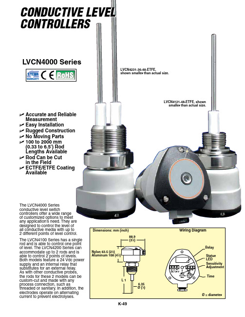
Electrodes: 316 SS Electrode Length: 100 to 2000 mm (3.9 to 6.5') Output Voltage of Electrodes: 12V to 100 Hz Weight: Approx. 2.7 kg (6 lb) for 1.2 m (4') Protection Class: NEMA 4 (IP65)
metallic tank wall or another rod for non-metallic tanks.
Options
Ordering Suffix
Description
A-Process Connection
1
1⁄2 NPT thread
2
3⁄4 NPT thread
3
1 NPT thread
LVCN42(A)(B)-(C) Custom conductive level controller, dual rod, select process connection (A), enclosure (B), and rod length in inches (C)
* Rods must be coated when using the probes above 82°C (180°F). All conductive applications must have a reference point, such as the
Specifications
Power Supply: 24 Vdc (±10%) Current Consumption: Maximum 2 VA Temperature Range:
316 SS: -10 to 82°C (-14 to 180°F) ETFE: -10 to 120°C (-14 to 248°F) Maximum Pressure: 290 psi (20 bar) Wetted Materials: 316 SS Enclosure Material: Glass-filled nylon standard, aluminum optional
艾特顿电能专家电能表4000产品说明书

Eaton PXM4251A1BBEaton Power Xpert Meter 4000, 2 GB, Standard 100-240 Vac or110-250 Vdc power supply, Communications expansion card with10/100 Base-T, 100F, RS-485, RS-232 ports, I/O option card (8digital inputs, 2 solid state outputs, 3 relay outputs)General specificationsEaton Power Xpert meter 4000PXM4251A1BB7866854248429.56 in8.32 in 6.72 in7.1 lb 1 yearCE MarkedCFR 47 FCC Part 15IEC 60687ANSI/IEEE Std C12.20 EN 60687UL Listed file 61010-1 IEC 61326EN 61010-1Product Name Catalog Number UPC Product Length/Depth Product Height Product Width Product Weight Warranty Compliances Certifications4096 Oversampling/cycleTo 127thLED alarm indicatorAudible AlarmMin/Max LogTime / date stampEvent LogData LoggingStandard communications module with RS-485Crest FactorNumber Of 9'S AvailabilityK-FactorView Harmonic Spectrum At DevicePQ Index Graph -STDCommunications expansion card with 10/100 Base-T, 100F, RS-485, RS-232 ports2 GBFiber-optic Ethernet PortModbus RTU (RS-485) :2nd10/100 RJ-45 Ethernet PortModbus TCPBACnet/IPInternet/HTTP Server built-in1xRS-485Network Time Protocol (NTP)Email (SMTP)1 x Local Ethernet Port for configurationSimple Network Management Protocol (SNMP)File Transfer Protocol (FTP) built-inCurrent & Voltage - Per PhaseTime Of Use Energy Eaton's enclosed meter familyPower Xpert Meter 4000/6000/8000 meter advanced 12-inch touch screen displayPower Xpert Meter 4000/6000/8000 power quality and energy meter Power Xpert Meters 4000/6000/8000Enterprise Data Center SolutionsEaton's Power Xpert: the heart of Ave Maria University's cost-saving power monitoring systemMetering devicesEaton's Volume 3—Power Distribution and Control AssembliesBack to back meter to display projection mount adapter kit assembly instructions for PXM 6 display (PX-PMBD)Power Xpert Meter 4000/6000/8000 User Manual Addendum for DNP 3.0First generation PXM 4/6/8K meter 6 color touchscreen display quick start guidePower Xpert Meter 4000/6000/8000 quick start guideFirst generation PXM 4/6/8K meter quick start guide with Java UI BACnet object list for Power Xpert Meter 4000/6000/8000First generation PXM 4/6/8K meter user and installation manual with Java UIPower Xpert meter mobile quick start guidePower Xpert Meter 4000/6000/8000 user and installation manualFirst generation PXM 4/6/8K meter quick start guideModbus register map for Power Xpert meter 4000/6000/8000PXM 4/6/8K DNP3 Ethernet communcations user manualFirst generation PXM 4/6/8K meter advanced display quick start guide with JavaFirst generation PXM 4/6/8K meter DNP3 Ethernet communications user manualThe New Power Xpert Meter Web Interface, Step 1: Getting Started withWaveform capture sampling rate %Thd - current and voltage LoggingModification 1Power quality analysis Modification 2MemoryCommunications Instrumentation BrochuresCase studiesCatalogsInstallation instructions Manuals and user guidesMultimediaFrequencyVa demandCurrent & Voltage - 3 Phase AverageDemand MeteringApparent Power FactorWatt DemandVahCurrent & Voltage - 3 Phase Min, MaxCurrent & Voltage - % Phase Unbalance - EVENT SETTING ONLYView current & voltage phasors on displayGround CurrentVoltage Neutral-GroundVaPer Phase Power FactorCurrent DemandWh --NetVarsDisplacement Power FactorWattsWh --Positive & NegativeVarhNeutral Current4 Quadrant EnergyStandard power qualityVoltage Disturbance Wave Capture TriggerExcess Dv/Dt Or Interruption Capture TriggerWaveform Captured On Threshold / InputWaveform recording duration - 60 cyclesCaptured Waveforms Displayed on Meter/GUIComtrade - Standard IEEE File FormatTo 85th5ALoad SheddingProg. Pulse Output --Wh, Varh, VahKYZ outputProgrammable Discrete Inputs - 8Voltage Disturbance TripProgrammable Relay Outputs -5Synchronize Demand Window Pulse Input the New UIUpgrading your Power Xpert Meter to HTML5, PXM 4/6/8K Series EditionPower Systems Experience Center Tour – Metering FocusThe New Power Xpert Meter Web Interface, Step 3: Navigating the New UIThe New Power Xpert Meter Web Interface, Step 4: Accessing the Meter with a TabletPower Xpert MetersThe New Power Xpert Meter Web Interface, Step 2: Navigating the New UIEaton Power Xpert Meter 4000/6000/8000 power quality and energy metersNext generation power quality meters white paperTypeWaveform analysisIndividual harmonics magnitude Current sensor inputI/O capability Specifications and datasheets White papersEaton Corporation plc Eaton House30 Pembroke Road Dublin 4, Ireland © 2023 Eaton. All Rights Reserved. Eaton is a registered trademark.All other trademarks areproperty of their respectiveowners./socialmediaC12.20 (0.2)I/O option card (8 digital inputs, 2 solid state outputs, 3 relay outputs)100-240 V, 110-250 VdcANSI % revenue accuracy Modification 3Power supply voltage。
PD4000系列电源控制中心使用指南说明书

PD4000 Series Power Control CenterExtended warranties areavailable for purchase atINSTALLATION INSTRUCTIONSMOUNTING:∙ The PD4000 series POWER CONTROL CENTER should be installed horizontally (converter section to the left). ∙ Unit is NOT ignition protected.∙ Do not mount in the LP gas or the battery compartment.∙ The INTELI-POWER converters are not designed for zero clearance compartments.∙ The POWER CONTROL CENTER is not designed for wet or damp locations. Install in an interior / dry location. ∙ Cut mounting hole to approximately 10-3/4” wide x 7-1/4” high.∙ The OEM should test the POWER CONTROL CENTER converter under full load conditions in its intended mountinglocation to ensure proper ventilation. Failure to provide adequate ventilation will prevent the converter from supplying full output power.AC ELECTRICAL:∙ Connect wiring system using proper connections and appropriately sized cable clamp. ∙ Connect CONVERTER AC HOT (black) wire to a 15A circuit breaker.Approved breakers (main and branch): o Thomas & Betts – TB & TBBD series o Square D – HOM & HOMT series o Cutler Hammer/Bryant – BR & BRD serieso GE – HACR seriesApproved Filler Plates o ITE/Siemens – QF3 o GE – TQLFP1∙ from Progressive Dynamics, Inc. Part Number PD812374.DC ELECTRICAL:∙ For installations without an external DC disconnect switch:1. 2. Connect battery NEG (-) lead to the BATTERY GND/WHT (-) lug. 3. The POS/DC DISC. (+) lug is not used.∙ For installations incorporating an external DC disconnect switch:1. Connect battery POS (+) lead and the BATTERY POS/BLK (+) lead to the same pole on the external disconnect switch.2. Remove the JUMPER.3. Connect the POS/DC DISC (+) lead to other pole on the external disconnect switch.4. Connect battery NEG (-) lead to the BATTERY GND/WHT (-) lug.Wiring Diagram(Below image may vary, depending on model)CONVERTER GND/WHT (-) CONVERTER POS/BLK (+) JUMPER POS/DC DISC(+)MAIN BREAKER HOLD DOWN MAIN BREAKER (NOT SUPPLIED)AC HOT IN (BLACK) AC GROUND IN(GREEN)AC NEUTRAL (WHITE) CONVERTER HOT (BLACK) REVERSE BATTERY LED BATTERY GND/WHT (-) BATTERY POS/BLK (+) CONVERTER GND (GREEN) CONVERTER NEU (WHITE)GENERAL OPERATIONThe INTELI-POWER series converter will supply "clean" power from input voltages that range from 105 - 130VAC.The INTELI-POWER series of converters are primarily designed for use with a battery, however, the output of the INTELI-POWER converters are a regulated, filtered DC voltage that can power sensitive electronics without the need for a battery or other filtering.At normal input voltages (105 – 130VAC) the full load rated capacity is available. At input voltages less than 105 VAC the converter may not supply full rated output capacity.The optional OUTPUT MODE SWITCH sets the converter output to either a constant 14.6VDC with the Charge Wizard ® disabled (switch in ‘LI’ position) or a nominal 13.6VDC with full Charge Wizard ® function (switch in ‘LA’ position). ‘LI’ mode is intended for use with lithium batteries with a BMS requiring a constant converter output. ‘LA’ mode is intended for use with lead/acid batteries where the Charge Wizard ® will optimize battery charging.NOTE:The OUTPUT MODE SWITCH should only be switched when new batteries are installed. Verify battery typebefore adjusting the output mode switch.PD4045/60L ‐ The full rated load is available for load, battery charging or both. When functioning as a regulated battery charger the converter has a nominal voltage output of 14.6 VDC. The system is designed to sense voltage on the battery and will taper the charging current as the battery becomescharged.CAUTIONThe 4000L series converter/chargers are designed to recharge lithium iron phosphate (LiFePO4)batteries only.DO NOT USE TO RECHARGE LEAD/ACIDBATTERIES!PD4045/60 - The full rated load is available for load, battery charging or both. When functioning as a regulated battery charger the converter has a nominal voltage output of 13.6 VDC. The system is designed to sense voltage on the battery and automatically selects one of three operating modes(normal, boost and storage) to provide the correct charge level to the batteries.See website for detailed explanation of Charge Wizard ®functionCAUTIONIT IS IMPORTANT THAT THE FLUID LEVEL OF ANY CONNECTED BATTERIES BE CHECKED ON A REGULAR BASIS. ALL BATTERIES WILL“GAS” AND LOSE SOME FLUIDS WHEN CONTINUOUSLY CONNECTED TO ANYCHARGING SOURCEDC SECTION FEATURESThe REVERSE BATTERY PROTECTION CIRCUIT protects the converter in the event a battery is accidentally hooked up backwards. Easily accessible ATC type fuses will blow when a battery is connected in reverse. Correct battery wiring and replace fuses with same type and rating to restore proper operation.The use of optional, genuine WAGO ® quick-flip connectors offers a more secure wire connection than the traditional screw terminal block connections.The DC panel features up to 12 fused positions rated for up to 30 amps, depending on model, for accessories including ten low-to-full current rated branches. Each branch has an optional LED to indicate a blown branch fuse.NOTE: Disconnect all power to the converter prior to checking or changing fuses!CAUTIONFOR CONTINUED PROTECTION AGAINST RISK OF FIRE OR ELECTRICAL SHOCK, REPLACE ONLY WITH SAME TYPEAND RATING FUSE.FanFront of UnitOutput Mode Switch LocationSpecifications(Specifications subject to change without notice)ModelPD4045(LI) PD4060(LI) AC Section120 VAC 30 Amps Maximum** - 7 Branch Circuits Max * DC Section 12 VDC 60A Max. - 12 Branch Circuits 12 VDC 75A Max - 12 Branch CircuitsConverter SectionInput: 105-130 VAC 50/60 Hz725 WattsOutput: 13.6-14.6 VDC (14.6 VDC)45 Amps Weight: 5.70 lbsInput: 105-130 VAC 50/60 Hz1000 WattsOutput: 13.6-14.6 VDC (14.6 VDC)60 Amps Weight: 6.35 lbs* Consult local regulatory authority for possible branch circuit restrictions ** Maximum continuous loads on main or branch circuits not to exceed 80% of thecircuit breaker ratingsTROUBLESHOOTING GUIDEPROBLEMPOSSIBLE CAUSESACTIONNo OutputProper AC power not connected Connect power supplyCheck AC distribution panel for proper operation Reverse battery fuses blownCheck for reverse battery connection. Replace fuses with same type and ratingShort circuitTrace circuits for possible fault Unit has shutdown due to overheating Check air flow Allow unit to cool Unit has shutdown due to over voltage(Converter will shut down if the input voltage exceeds 132 VAC)Check input voltage Correct input voltage Low OutputCompartment gets too hotCheck air flow to the converter Improve ventilation to the compartmentExcessive load for converterReduce load requirements or install larger converter Input voltage not between 105-130 VAC Correct input supply voltage Bad battery cell(s)Replace batteryIntermittent or no Output on Generator, works on Shore Power Unit has shutdown due to over voltage.Add another load to the generator, this may reduce the “spikes” to an acceptable levelSome generators exhibit excessive voltage spikes on the AC power output, this may cause the over voltage protection to shut the unit down Contact generator manufacturer for possible defect in the generator Battery does not charge but circuits have powerReverse battery fuses blown. Check battery polarity. Correct if necessary. Replace fuses. No battery connection.Check wiring to battery including possible inline fuse.See website for more trouble shooting information and return instructions.。
DEC-1000和DEC-4000控制器操作说明书讲述
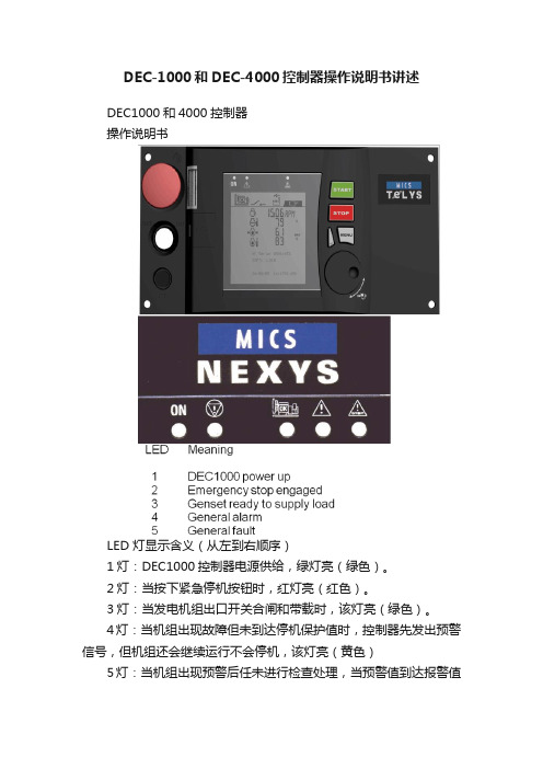
DEC-1000和DEC-4000控制器操作说明书讲述DEC1000和4000控制器操作说明书LED 灯显示含义(从左到右顺序)1灯:DEC1000控制器电源供给,绿灯亮(绿色)。
2灯:当按下紧急停机按钮时,红灯亮(红色)。
3灯:当发电机组出口开关合闸和带载时,该灯亮(绿色)。
4灯:当机组出现故障但未到达停机保护值时,控制器先发出预警信号,但机组还会继续运行不会停机,该灯亮(黄色)5灯:当机组出现预警后任未进行检查处理,当预警值到达报警值时,机组立即自动停止运行进行保护,该灯亮(红色)当机组运行时,RPM:显示机组运转的速度(1500转/分);同时显示机组运行时,充电机输出电压值:13.6V(直流)。
显示:控制器运行累计时间:23589小时;显示:发电机组输出电源频率:50Hz;显示:电池电压13.6V显示:柴油量在油箱的百分比值:37%显示:冷却液温度:85℃(水温)显示:机组运行中机油压力:3.2BAR以上为公制单位显示:柴油量在油箱的百分比值:37%显示:冷却液温度:85F(水温)显示:机组运行中机油压力:40-60PSI以上为英制单位显示:L1-L2相电压:404V;显示:L2-L3相电压:403V;显示:L3-L1相电压:401V显示:L1-N线电压233V;显示:L2-N线电压233V;显示:L3-N线电压232V.显示:L1相电流530A显示:L2相电流537A显示:L3线电流548A机侧启动1、将控制器上钥匙开关从左侧向右侧旋转,打开控制器电源,控制指示灯亮及液晶屏出现文字显示,控制器并读取程序;2、控制器绿色灯亮,说明机组无故障,准备就绪;3、按下“START”绿色按钮,机组立即进行预热10秒,10秒后机组立即启动,机组启动成功允许;4、读取机组允许参数:按下“左侧白色按钮”,每按一次,显示一组参数,其中参数包括:发动机转速、水温、机油压力、3相电压及频率、3相电流、电池电压等;5、按下“STOP”按钮,机组立即停止运转。
4000说明书

XY1000-3000火灾报警系列产品JB-QB-XY1000-3000火灾报警控制器(联动型)使用说明书大连欣洋电子消防设备有限公司二OO三年九月1概述1.1 JB-QB-XY1000-3000火灾报警控制器(联动型)是根据国家最新联动标准GB16806-1997《消防联动控制设备通用技术条件》和GB4717-93《火灾报警控制器通用技术条件》研制开发的新一代高科技产品。
控制器采用MCS-51系列单片机CPU及外围芯片构成。
该控制器所挂接各种探测器、模块等设备均采用P87LPC76X系列单片机控制,并采用无极性二总线方式从而构成科学的、先进的分布智能式火灾报警系统。
1.2 该控制器采用大屏幕全汉字液晶显示,并挂有了国家标准二级字库,使各种警情的提示信息详尽准确。
融合了当今广泛普及的计算机与手机中大家都熟悉的操作方式,使日常操作,维护变得简单、容易,相信会使用户感到方便。
1.3本机具有强大而操作又很简单的现场编程功能,能够满足各种复杂的逻辑关系要求,达到报警时准确、可靠地启动现场设备;科学合理地达到灭火的要求。
1.4该控制器必须同本公司生产的外部设备配合,组成火灾报警控制系统。
另外该控制器的壁挂型还设8 组多线直接输出接点。
可直接启停消防泵等重要外部设备。
1.5本机采用金属喷塑外壳;面板采用丝印技术工艺;轻触式按键;超高亮的指示灯;动态液晶显示画面;超强功能,高可靠的稳定性,相信会赢得用户的信赖和满意。
2 基本原理及主要特点2.1 基本原理火灾报警控制器的主要功能是准确地向人们报告火灾信息,这是众所周知的道理,那么如何能让火灾报警控制器报警准确,也就是尽可能减少误报警,这一直是从事火灾报警研究人员的研究课题。
模拟量火灾报警系统虽然在一定程度上减少了系统的误报率,但还是没有将系统设计为最佳,因此人们还是一直在寻求更佳的设计方案。
九十年代后期,微型单片机技术的发展给智能化设计带来了革命,很多领域均开始应用智能化设计产品。
- 1、下载文档前请自行甄别文档内容的完整性,平台不提供额外的编辑、内容补充、找答案等附加服务。
- 2、"仅部分预览"的文档,不可在线预览部分如存在完整性等问题,可反馈申请退款(可完整预览的文档不适用该条件!)。
- 3、如文档侵犯您的权益,请联系客服反馈,我们会尽快为您处理(人工客服工作时间:9:00-18:30)。
DCK-4230/4231/4232/4332电导率仪使用说明
一、使用前注意事项:
1、安装、使用前请详细阅读本说明书相关章节,防止错误操作,造成测量误差或仪
表损坏。
2、不恰当的安装和不合适的流速会使测量出现很大偏差,请详细了解安装章节。
3、此仪表属于精密电化学仪表,应由了解和掌握该专业知识的人员负责安装、操作。
二、保修条款:
1、自购买之日起,产品质量保证期为一年。
在质量保证期内,产品出现质量问题,
公司负责免费维修或更换产品。
2、公司对售出产品提供终身维护服务。
3、对下列原因造成产品的损坏,不在保修范围之内:
A、使用、维护不当造成的烧毁、浸水;
B、未经许可进行的改装和误用;
C、超出本公司产品规定的使用环境造成的损坏;
D、因选型不当造成的附带损失;
E、安装、使用不当造成的线缆断裂、损坏;
F、私自拆线或接线造成传感器测量不准;
G、不谨慎拆卸造成的接头内部断线。
一、产品概述:
DCK-4000系列工业在线电导率仪是工业流程水质连续测量与控制的分析仪表,采用一个内藏的微
型计算机芯片存储、计算、补偿和有关测定电导率值的所有计算参数,例如:溶液电导率的常数修正,温度补偿,参数之间的相互换算,各项信号输出和控制的设定。
丰富的软件功能,使的本系列仪表具
有功能完善、操作方便,抗干扰性强,测量准确,运行稳定,工作可靠,标准化程度高和极少维护等
特点。
广泛应用于反渗透、电渗析,海水淡化,化学制程,中水回用及各种水处理装置作水质连续监控;水冷却系统、中央空调、锅炉底水的电导率监视控制和药剂投加。
特点:
1.新一代翠绿色、大型字段式背景光液晶屏,具有多种提示符号及状态显示支持μS/cm,ppm (TDS),mS/cm,TEMP(温度)多功能选择显示;
2.支持多种电极常数和电极离散性校正(0.1 cm-1 ;1.0cm-1;10cm-1);
3.指定量程/自动量程双选择设定,可选的上限/下限动作模式,双路继电器构成三位控制;
4.仪表/变送器双模式传送,隔离型、可迁移4~20mA电流环,适配所有国别、型号的PLC模块(DCK-4332型号),具有强大的兼容性。
5. 友好的人机交互界面,强大的软件功能,键盘式设置方式。
具有优越的抗电磁干扰能力,独享
的新型外观专利设计。
6.阶梯式功能选择,满足多个层次的应用需求,兼顾用户低成本的采购理念,超值的性能价格比。
二、型号、基本功能:
注:仪表上电初始瞬间液晶屏显示该仪表的型号。
例如4230/4231/4232/4332,作为仪表型号、功能的识别。
三、主要技术指标
电导率测量范围:
DCK-4000系列: 0~20、0~200μS/cm(配0.1cm-1电极);
0~20、0~200、0~2000μS/cm(配1.0 cm-1电极);
0~200、0~2000μS/cm、0~20mS/cm(配10.0 cm-1电极)
DCK-4000A系列:0~40、0~400μS/cm(配0.1cm-1电极);
0~40、0~400、0~4000μS/cm(配1.0 cm-1电极);
0~400、0~4000μS/cm、0~40mS/cm(配10.0 cm-1电极)准确度:1.5%(FS)
稳定性:±2×10⁻³(FS)/24h
配套电极:电极常数:0.1cm-1 □、1.0cm-1 □、10cm-1□
电极材质:塑料□、316L不锈钢□、钛金属□
温补元件:NTC
温度补偿:以25℃为基准,数字化自动补偿
介质温度:5~50℃
显示方式:电导率: 31/2位;温度:3位LCD数字显示
螺纹尺寸:1/2"管螺纹□ 3/4"管螺纹□
介质压力:0~0.5MPa
线缆结构:RVP+同轴75-2双屏蔽
线缆长度:5m或约定______m
输出电流信号:隔离型、可迁移4~20mA输出,仪表/变送器模式可选择触点形式:双继电器,ON/OFF,5A/250V AC(阻性负载时)
环境条件:温度:0~50℃;湿度:≤85%RH
供电电源:AC 220V±10% 50Hz
电源消耗:≤3W
四、仪表安装
1.仪表外形尺寸:96×96×130mm(高×宽×深)
2.表盘开孔尺寸:91×91mm(高×宽)
3.安装方式:面板嵌入式(见安装图)
五、设置与操作:
1.键盘说明:
2.参数设定:
注1: 输入的电极常数值
输入的电极常数值以电极标注常数或实际常数为准。
a.选用0.1 cm-1电极时,菜单输入的电极常数值为标注值×10;
b.选用1.0 cm-1电极时,菜单输入的电极常数值为标注值×1.0;
c.选用10.0 cm-1电极时,菜单输入的电极常数值为标注值×0.1。
注2:TDS量程范围
TDS量程范围=电导率量程/TDS系数。
例1:在TDS系数为2,电导率量程为0~20μS/cm时,TDS量程为0~10 ppm;在TDS系数为2.5,电导率量程为0~20μS/cm时,TDS量程为0~8ppm。
六、仪表接线:接线端子连接法:
(1) 4~20mA输出+(mA+)
(2) 4~20mA输出 - (mA-)
(5) 电导率电极白线端CELL(W)
(6) 电导率电极绿线端NET(G)
(7) 电导率电极黄线端CELL(Y)
(8) 电导率电极红线端T(R)(9) 第1路报警继电器常开触点
(10)第1路报警继电器常闭触点
(11)第1、第2路继电器公共触点
(12)第2路报警继电器常开触点
(13)第2路报警继电器常闭触点(15)、(16)接电源220V AC
NC为空端子,内部无连接
DCK-4231
DCK-4231A
DCK-4230 DCK-4230A
DCK-4232 DCK-4232A DCK-4332 DCK-4332A
注:DCK-4332 mA输出接线法:
当选用仪表模式输出时,(2)4~20mA输出+(mA+)(3) 4~20mA输出 -(mA-)
当选用变送器模式输出时,(1)+DC24V IN (2) 4~20mA输出+(mA+)
4~20mA输出接线方式如下图所示:
控制电路的接线:
仪表内的继电器驱动能力有限,尤其在驱动电感性负载时(通电瞬间电流将达到5~10倍的运行电流,断电时接点承受2倍电源电压的电势),需要使用中间继电器或磁力接触器来扩展驱动能力。
+24V
七、举例说明双路继电器的使用
八、测量电极:
1. 测量电极选型:
测量电极的常数与电解质的浓度(电导率)成正比关系,电导电极与测量范围的对应关系如下表所示,通常在线电导/电阻率仪表与电导电极的配套是在出厂前由厂家来完成的,订货时只需说明测量介质的电导率范围就可以了。
2.测量电极安装
为确保电极测量结果真实,请正确选择和安装电导池,应避免电导池间出现气泡集聚或静止死水造成数据失准,请严格按下图安装:
(1)CELL外观
(2)T形三通流通槽安装方式
(3)Y型三通流通槽安装方式
注意事项:
(1)电极应安装在管路中流速稳定且不易集聚气泡处。
(2)电极平装、斜装或竖装都应使电导池迎水安装,并深入到活动水体以免出现静止死水造成测量错误。
(3)电导池测量信号属微弱电信号,其采集电缆应独立走线,禁止和动力线、控制线连接在同一组电缆接头或端子板中,以免干扰或击穿测量单元。
(4)测量电缆需加长时,请在供货前约定。
(5)电极测量部分清洁,不要用手直接接触表面,避免接触脂类物体。
九、维护保养
1.测量电极是精密部件,不可分解,不可改变电极形状和尺寸,也不可用强酸、碱清洗,以免改变
电极常数,影响仪表的测量精度。
2.测量电缆为专用电缆,不可更换。
3.仪器采用精密集成电路和电子元件组装,应安置于干燥环境或控制箱内,避免因水滴溅射或过度
潮湿引起仪表漏电或测量误差。
4.为保证安装操作安全,在安装完毕检查无误后再接通电源。
十一、计量检定方法
十二、仪器成套性
面板表一台传感器一支固定夹一付说明书一册合格证一个
新品介绍:
1.DCK-7000系列的介绍(包括3900)
2.反渗透控制器的介绍(ROC2313、ROC8221、ROC4313)。