BCU83-SMD中文资料
S-80842CNNB-B83T2G中文资料

元器件交易网
SUPER-SMALL PACKAGE HIGH-PRECISION VOLTAGE DETECTOR S-808xxC Series
Rev.4.3_00
Product Name Structure
The detection voltage, output form and packages for S-808xxC Series can be selected at the user's request. Refer to the "1. Product Name" for the construction of the product name and "2. Product Name List" for the full product names. 1. Product Name 1-1. SC-82AB, SOT-23-5, SOT-89-3, SNT-4A packages
Seiko Instruments Inc.
1
元器件交易网
SUPER-SMALL PACKAGE HIGH-PRECISION VOLTAGE DETECTOR S-808xxC Series Block Diagrams
1. Nch Open-drain Output Products
S - 808xx
C
x
xx
-
xxx
ห้องสมุดไป่ตู้
xx
G IC direction in tape specifications*1 T2: SC-82AB, SOT-23-5, SOT-89-3 TF: SNT-4A Product code*2 Package code NB: SC-82AB MC: SOT-23-5 UA: SOT-89-3 PF: SNT-4A Output form N: Nch open-drain output (Active Low) L: CMOS output (Active Low) Detection voltage value 08 to 60 (e.g. When the detection voltage is 0.8 V, it is expressed as 08.)
前向通道与数据采集2

在输入上述各位后ADC0838进行逐位转换,一边转换一 边输出数据,在CLK时钟信号的下降沿同步下,数据从DO 端输出。 ADC0838的工作时序如图7-24所示
ADC0838属于逐次逼近ADC,因此,转换速 度不会因串行输出而降低 另外,在保持器作用下,待转换的模拟量 保持不变,转换精度得到了保证,这也是 串行逐次逼近A/D转换技术的奇妙之处。
1) AD083X串行A/D转换器简介
AD083X系列为8位高速串行接口A/D转换 器,具有多路选择、基准电压源、跟踪保 持功能。 AD083X有4个品种:ADC0831、ADC0832、 ADCO834、ADC0838,它们分别有1、2、4、 8路单端模拟量输入通道,也可作为1、1、 2、4路差分模拟输入通道。
ADC0808/0809的主要性能可以总结如下:
分辨率为8位 转换精度ADC0808为0.75LSB,ADC0809为1.25LSB 单一+5V供电,模拟输入范围为0∼5V 具有锁存控制的8路模拟开关 可锁存三态输出,输出与TTL兼容 功耗为15mW 不必进行零点和满刻度调整 转换速度取决于芯片的时钟频率。时钟频率范围为 10∼1280kHz,当时钟CLK=500kHz时,转换速度为100µs
0808/0809与8031单片机的硬件接口图
中断方式下的接口电路与查询方式基本相 同,只是将在查询方式下不使用的EOC脚经 过反相后接到8031的INT0(也可接INT1)端。 由主程序启动A/D转换,转换结束后ADC向主 机8031申请中断,主机则用中断方式读取转 换结果。
程序的外部接口描述如下:
;====启动ADC子程序 START ADC: MOV ADC-CHAN,#0 ;初始化通道号 CLR FLAG_ADC ;清除采样结束标记 MOV DPTR,#ADC-ADDR MOV A,ADC_CHAN MOVX @DPTR,A ;启动ADC
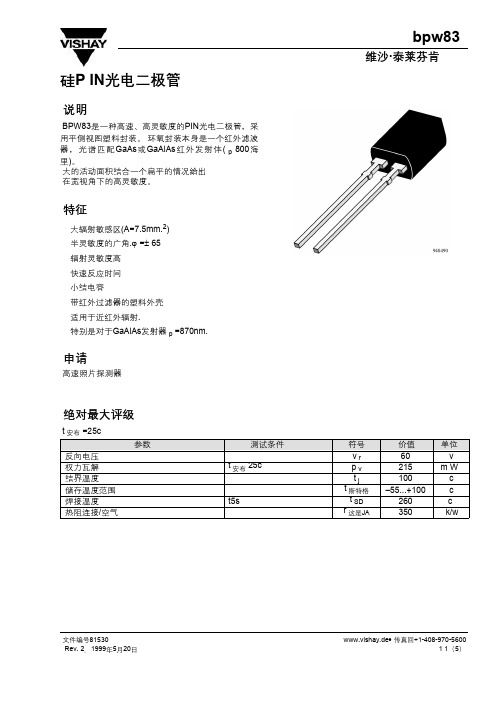
BPW83中文版数据手册
测试条件
i r =100a,e=0. v r =10v,e=0 v r =0V,f=1MHz,E=0 v r =3V,f=1MHz,E=0 e e =1米W/cm2 =870nm e e =1米W/cm2 =870nm e e =1米W/cm2, =870nm,V r =5v
v r =10V,=870nm v r =10伏,r l =1k, =820纳米 v r =10伏,r l =1k, =820纳米
使用有关的任何人身损害、伤害或死亡索赔而引起的所有索赔、费用、损害和费用。
维沙半导体公司H,P.O.B。 电话:49(0)7131672831,传真号码: 49(0)7131672423
文件编号81530 Rev. 2,1999年5月20日
www.vishay.de 传真回+1-408-970-5600 5 1(5)
臭氧消耗物质政策声明
bpw83
维沙·泰莱芬肯
这是Vishay半导体公司的政策
1. 满足目前和未来所有国家和国际法定要求..
2. 定期和持续地改进我们的产品,工艺,分销和操作系统的性能,使其对我们员工和公众的健康和安全以及对环境 的影响..
特别令人关注的是控制或消除这些物质向大气中的释放,即所谓的消耗臭氧层物质。
10
1
0.1
1
10
100
948415
v r 反向电压(V)
图4. 反向光电流与。 反向电压
80
60
c d 二极管电容(p F)
40
20
0
0.1
1
10
100
948407
v r 反向电压(V)
图5. 二极管电容与。 反向电压
安森美半导体-BC847C-NPN通用SMD三极管-数据表说明书

Ratings (at TA = 25°C unless otherwise specified)
Symbol
Collector Capacitance at f = 1MHz IE = Ie = 0; VCB = 10V
CC
Transition Frequency at f = 100MHz IC = 10mA; VCE = 5V
Symbol VCES VCEO ICM Ptot Tj
Maximum
Dimensions : Millimetres
BC847C 50 45 200 250 150
Units
V
mA mW °C
Page 1
09/05/08 V1.1
BC847C
General Purpose SMD NPN Transistors
10
Ptot (mW)
250
Device Marking
IG
Part Number BC847C
Unit pF MHz dB
-
-
Page 3
09/05/08 V1.1
BC847C
General Purpose SMD NPN Transistors
Notes:
International Sales Offices:
Package Outline Details
Absolute Maximum Ratings
Collector-Emitter Voltage (VBE = 0) Collector-Emitter Voltage (Open Base) Collector Current (Peak Value) Total Power Dissipation up to Tamb = 25°C Junction Temperature
AO4459中文资料

AO4459中⽂资料SymbolTyp Max 33406275R θJL 1824Maximum Junction-to-Lead CSteady-State°C/WThermal Characteristics ParameterUnits Maximum Junction-to-AmbientAt ≤ 10s R θJA °C/W Maximum Junction-to-Ambient ASteady-State °C/W AO4459AO4459SymbolMin TypMaxUnits BV DSS -30V -1T J =55°C-5I GSS ±100nA V GS(th)-1.5-1.85-2.5V I D(ON)-30A 3846T J =125°C53685872m ?g FS 11S V SD -0.78-1V I S-3.5A C iss 668830pF C oss 126pF C rss 92pF R g69?Q g (10V)12.716nC Q g (4.5V) 6.4nC Q gs 2nC Q gd 4nC t D(on)7.7ns t r 6.8ns t D(off)20ns t f 10ns t rr 2230ns Q rr15nCTHIS PRODUCT HAS BEEN DESIGNED AND QUALIFIED FOR THE CONSUMER MARKET. APPLICATIONS OR USES AS CRITICAL COMPONENTS IN LIFE SUPPORT DEVICES OR SYSTEMS ARE NOT AUTHORIZED. AOS DOES NOT ASSUME ANY LIABILITY ARISING OUT OF SUCH APPLICATIONS OR USES OF ITS PRODUCTS. AOS RESERVES THE RIGHT TO IMPROVE PRODUCT DESIGN,FUNCTIONS AND RELIABILITY WITHOUT NOTICE.DYNAMIC PARAMETERS Maximum Body-Diode Continuous CurrentGate resistanceV GS =0V, V DS =0V, f=1MHzV GS =0V, V DS =-15V, f=1MHz Input Capacitance Output Capacitance Turn-On Rise Time Turn-Off DelayTime V GS =-10V, V DS =-15V, R L =2.5?, R GEN =3?Turn-Off Fall TimeTurn-On DelayTime SWITCHING PARAMETERSTotal Gate Charge (4.5V)Gate Source Charge Gate Drain Charge Total Gate Charge (10V)V GS =-10V, V DS =-15V, I D =-6.5Am ?V GS =-4.5V, I D =-5AI S =-1A,V GS =0V V DS =-5V, I D =-6.5AR DS(ON)Static Drain-Source On-ResistanceForward TransconductanceDiode Forward VoltageI DSS µA Gate Threshold Voltage V DS =V GS I D =-250µA V DS =-24V, V GS =0VV DS =0V, V GS =±20V Zero Gate Voltage Drain Current Gate-Body leakage current Electrical Characteristics (T J =25°C unless otherwise noted)STATIC PARAMETERS ParameterConditions Body Diode Reverse Recovery Time Body Diode Reverse Recovery ChargeI F =-6.5A, dI/dt=100A/µsDrain-Source Breakdown Voltage On state drain currentI D =-250µA, V GS =0V V GS =-10V, V DS =-5V V GS =-10V, I D =-6.5AReverse Transfer Capacitance I F =-6.5A, dI/dt=100A/µs A: The value of R θJA is measured with the device mounted on 1in 2FR-4 board with 2oz. Copper, in a still air environment with T A =25°C. The value in any a given application depends on the user's specific board design. The current rating is based on the t ≤ 10s thermal resistance rating.B: Repetitive rating, pulse width limited by junction temperature.C. The R θJA is the sum of the thermal impedence from junction to lead R θJL and lead to ambient.D. The static characteristics in Figures 1 to 6 are obtained using < 300µs pulses, duty cycle 0.5% max.E. These tests are performed with the device mounted on 1 in 2FR-4 board with 2oz. Copper, in a still air environment with T A =25°C. The SOA curve provides a single pulse rating. Rev0 Sept 2006AO4459AO4459。
ADC0809中文资料
A D C0809中文资料(总5页) -CAL-FENGHAI.-(YICAI)-Company One1-CAL-本页仅作为文档封面,使用请直接删除ADC0809是带有8位A/D转换器、8路多路开关以及微处理机兼容的控制逻辑的CMOS组件。
它是逐次逼近式A/D转换器,可以和单片机直接接口。
(1)ADC0809的内部逻辑结构由下图可知,ADC0809由一个8路模拟开关、一个地址锁存与译码器、一个A/D转换器和一个三态输出锁存器组成。
多路开关可选通8个模拟通道,允许8路模拟量分时输入,共用A/D转换器进行转换。
三态输出锁器用于锁存A/D转换完的数字量,当OE端为高电平时,才可以从三态输出锁存器取走转换完的数据。
(2).ADC0809引脚结构ADC0809各脚功能如下:D7-D0:8位数字量输出引脚。
IN0-IN7:8位模拟量输入引脚。
VCC:+5V工作电压。
GND:地。
REF(+):参考电压正端。
REF(-):参考电压负端。
START:A/D转换启动信号输入端。
ALE:地址锁存允许信号输入端。
(以上两种信号用于启动A/D转换)EOC:转换结束信号输出引脚,开始转换时为低电平,当转换结束时为高电平。
OE:输出允许控制端,用以打开三态数据输出锁存器。
CLK:时钟信号输入端(一般为500KHz)。
A、B、C:地址输入线。
ADC0809对输入模拟量要求:信号单极性,电压范围是0-5V,若信号太小,必须进行放大;输入的模拟量在转换过程中应该保持不变,如若模拟量变化太快,则需在输入前增加采样保持电路。
地址输入和控制线:4条ALE为地址锁存允许输入线,高电平有效。
当ALE线为高电平时,地址锁存与译码器将A,B,C三条地址线的地址信号进行锁存,经译码后被选中的通道的模拟量进入转换器进行转换。
A,B和C为地址输入线,用于选通IN0-IN7上的一路模拟量输入。
通道选择表如下表所示。
C B A选择的通道000IN0001IN1010IN2011IN3100IN4101IN5110IN6数字量输出及控制线:11条ST为转换启动信号。
BC856A中文资料

Ideally Suited for Automatic Insertion 150oC Junction TemperatureFor Switching and AF Amplifier ApplicationsMechanical DataCase: SOT-23, Molded PlasticTerminals: Solderable per MIL-STD-202, Method 208 Polarity: See DiagramWeight: 0.008 grams ( approx.)Type Marking Type MarkingBC856A 3A BC857C 3G BC856B 3B BC858A 3J BC857A 3E BC858B 3K BC857B3F BC858C3LMarking Code (Note 2)Maximum Ratings @ 25o C Unless Otherwise SpecifiedCharateristic SymbolValue Unit Collector-Base Voltage BC856BC857BC858V CBO -80-50-30VCollector-Emitter Voltage BC856BC857BC858V CEO -65-45-30V Emitter-Base Voltage V EBO -5.0V Collector Current I C -100mA Peak Collector Current I C M -200mA Peak Emitter CurrentI EM -200mA Power Dissipation@T s =50oC(Note1)P d310mWOperating & Storage TemperatureT j , T STG -55~150oCNote: 1.Package mounted on ceramic substrate 0.7mm X 2.5cm 2 area.2.Current gain subgroup “C” is not available for BC856Revision: 5 2008/01/01omp onents 20736Marilla Street Chatsworth! "# $ % ! "#Micro Commercial ComponentsFeaturesCase Material: Molded Plastic. UL Flammability Classification Rating 94V-0 and MSL Rating 1www.mccsemi .com1 of 3Electrical CharacteristicsNotes:1. Package mounted on ceramic substrate 0.7mm x2.5cm 2area.2. Current gain subgroup “C” is not available for BC856.3. Short duration pulse test to minimize self-heating effect.@ T A =25°C unless otherwise specifiedBC856A thru BC858CRevision: 5 2008/01/01Micro Commercial Componentswww.mccsemi .com2 of 3Revision: 52008/01/01Micro Commercial Componentswww.mccsemi .com3 of 3products are represented on our website, harmless against all damages.***APPLICATIONS DISCLAIMER******IMPORTANT NOTICE***Aerospace or Military Applications.Products offer by Micro Commercial Components Corp .are not intended for use in Medical,Micro Commercial Components Corp .reserve s the right to make changes without further notice to any product herein to make corrections, modifications , enhancements , improvements , or other changes .Micro Commercial Components Corp .does not assume any liability arising out of the application or use of any product described herein; neither does it convey any license under its patent rights ,nor the rights of others . The user of products in such applications shall assume all risks of such use and will agree to hold Micro Commercial Components Corp .and all the companies whoseOrdering InformationDevice Packing(Part Number)-TPTape&Reel;3Kpcs/Reel。
ADC0808中文资料_数据手册_参数

Operating Conditions (1)(2)
Temperature Range Range of VCC
TMIN≤TA≤TMAX −40°C≤TA≤+85°C ቤተ መጻሕፍቲ ባይዱ.5 VDC to 6.0 VDC
(1) Absolute Maximum Ratings indicate limits beyond which damage to the device may occur. DC and AC electrical specifications do not apply when operating the device beyond its specified operating conditions.
KEY SPECIFICATIONS
• Resolution: 8 Bits • Total Unadjusted Error: ±½ LSB and ±1 LSB • Single Supply: 5 VDC • Low Power: 15 mW • Conversion Time: 100 μs
Figure 2. PLCC
See Package N0028E
Package
See Package FN0028A
These devices have limited built-in ESD protection. The leads should be shorted together or the device placed in conductive foam during storage or handling to prevent electrostatic damage to the MOS gates.