MDESIGN_bolt_en(VDI2230计算公式)
IMDS材料数据系统使用指南(10.0版本)

1.4 1.5 1.6 127 日 2013 年 4 月 23 日
2013 年 5 月 24 日 2013 年 6 月 27 日
2013 年 12 月 12 日 2014 年 3 月 17 日 2014 年 7 月 13 日 2015 年 2 月 27 日 2015 年 4 月 27 日 2015 年 6 月 10 日 2015 年 6 月 11 日 2015 年 7 月 10 日
第3页
目录
1 IMDS – 简介.............................................................................................................................................................................................................. 7 2 IMDS – 使用入门 ...................................................................................................................................................................................................... 8
IMDS 服务中心 欧洲 | 电话: +36 1778-9821 | 电子邮件: imds-helpdesk-english@ 中国 | 电话: + 86 27 8743-1668 | 电子邮件: imds-eds-helpdesk-china@
MDESIGN bolt en VDI 计算公式
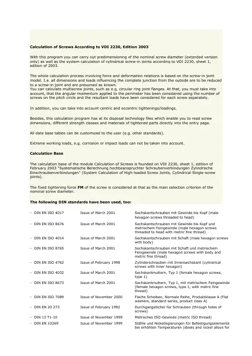
Calculation of Screws According to VDI 2230, Edition 2003With this program you can carry out predimensioning of the nominal screw diameter (extended version only) as well as the system calculation of cylindrical screw-in joints according to VDI 2230, sheet 1,edition of 2003.The whole calculation process involving force and deformation relations is based on the screw-in joint model. I.e. all dimensions and loads influencing the complete junction from the outside are to be reducedto a screw-in joint and are presumed as known.You can calculate multiscrew joints, such as e.g. circular ring joint flanges. At that, you must take into account, that the angular momentum applied to the perimeter has been considered using the number of screws on the pitch circle and the resultant loads have been considered for each screw separately.In addition, you can take into account centric and eccentric tightenings/loadings.Besides, this calculation program has at its disposal technology files which enable you to read screw dimensions, different strength classes and materials of tightened parts directly into the entry page.All data base tables can be customized to the user (e.g. other standards).Extreme working loads, e.g. corrosion or impact loads can not be taken into account.Calculation BaseThe calculation base of the module Calculation of Screws is founded on VDI 2230, sheet 1, edition of February 2003 "Systematische Berechnung hochbeanspruchter Schraubenverbindungen Zylindrische Einschraubenverbindungen" (System Calculation of High-loaded Screw Joints, Cylindrical Single-screw joints).The fixed tightening force FM of the screw is considered at that as the main selection criterion of the nominal screw diameter.The following DIN standards have been used, too:- DIN EN ISO 4017 Issue of March 2001 Sechskantschrauben mit Gewinde bis Kopf (malehexagon screws threaded to head)- DIN EN ISO 8676 Issue of March 2001 Sechskantschrauben mit Gewinde bis Kopf undmetrischem Feingewinde (male hexagon screwsthreaded to head with metric fine thread)- DIN EN ISO 4014 Issue of March 2001 Sechskantschrauben mit Schaft (male hexagon screwswith body)- DIN EN ISO 8765 Issue of March 2001 Sechskantschrauben mit Schaft und metrischemFeingewinde (male hexagon screws with body andmetric fine thread)- DIN EN ISO 4762 Issue of February 1998 Zylinderschrauben mit Innensechskant (cylindricalscrews with inner hexagon)- DIN EN ISO 4032 Issue of March 2001 Sechskantmuttern, Typ 1 (female hexagon screws,type 1)- DIN EN ISO 8673 Issue of March 2001 Sechskantmuttern, Typ 1, mit metrischem Feingewinde(female hexagon screws, type 1, with metric finethread)- DIN EN ISO 7089 Issue of November 2000 Flache Scheiben, Normale Reihe, Produktklasse A (Flatwashers, standard series, product class A)- DIN EN 20 273 Issue of February 1992 Durchgangslöcher für Schrauben (through holes ofscrews)- DIN 13 T1-10 Issue of November 1999 Metrisches ISO-Gewinde (metric ISO thread)- DIN EN 10269 Issue of November 1999 Stähle und Nickellegierungen für Befestigungselementebei erhöhten Temperaturen (steels and nickel alloys forfastening elements at higher temperature values)- DIN EN ISO 3506-1 Issue of March 1998 Mechanische Eigenschaften von Verbindungselementenaus nichtrost. Stählen (stress-strain properties ofconnectives made of stainless steels)- DIN 267-13 Issue of August 1993 Mechanische Verbindungselemente (mechanicallyconnected elements)- DIN EN ISO 898-1 Issue of November 1999 Mechanische Eigenschaften von Verbindungselementenaus Kohlenstoff –und legiertem Stahl (stress-strainproperties of connectives made of carbon and alloyedsteel)Special returns:- VDI-returns No. 1644, 2001 Schraubenverbindungen (screw joints)LimitationsThe calculation steps are valid for steel screws having the fastening thread with a flank angle of 60°. Service loads can be given as statically or dynamically acting axial forces. In addition, transverse forcesand service moments can be provided, too.All loads effecting the joint and the results connected with them are related only to a single-screw joint.The dimension of the juncture area in the level "screw axis - effect line of the working force" is limited bythe so-called measure G.The elastic flexibility of the tightened parts is presumed as linear variable. I.e., if the axial working force exceeds the separation force, the flexibility increases progressively and there is a loose connection,which can not be calculated by this program.Principally, working temperatures for the screw and the joint parts can be considered as explicitdepending on the material choice in the range of –270°C ≤ T≤ 700°C.Notice:All standard data bank records are stored from +20°C and depending on the chosen material till maximal 600°C!The jar washers can be also taken into account during the calculation. It is presumed then, that on thenut side and on the head side the dimensions and the materials are the same.Calculation of Screws - Formulae Symbols and TermsInputCalculation of Screws – Defining ResultsPredimensioning of the Nominal Screw Diameter, Calculation Process "Entwurf" ("Project")The calculation process "Entwurf" ("Project") enables predimensioning the nominal screw diameter using a minimum of input parameters.The definition of the nominal diameter is carried out depending on a chosen strength class according to the table A7 given in the supplement A of VDI 2230. Strength classes 8.8, 10.9 and 12.9 are there at your disposal.The following table is the calculation basis:Defining the appropriate diameter range is carried out in many sections sketched as follows:1. The next larger force for the given maximal axial force FAO is chosen in the column 1. If an additional maximal transverse force FQ and FA0 < (FQ) / (m Tmin) is specified, FQmax is used only.2. The required minimal preload force ensures, if the following number of steps (strings) continues from the above-named value:- at the fixed value according to FQmax:4 steps at choosing static or dynamic working load- at the fixed value according to FAO:2 steps for dynamically and eccentrically acting axial force1 step for dynamically and centrically or statically and eccentrically acting axial forceno step for static and centrically acting axial force3. The maximal tolerable minimal preload force ensures, if you continue the following number of steps (strings) from this value again:2 steps for tightening the screw using an impact screwdriver1 step for the torque-controlled tightening methodno step for the over-elastic yield-stress-controlled or rotation-angle-controlled tighteningmethod4. The defined value determines after choosing one of three strength classes (columns 2 - 4)the required nominal screw diameter. Besides the diameter, further geometric dimensions dependingon the screw type are shown in the result output. When switching to "Nachrechnung" (Recalculation)the done input values are automatically taken in.Notice:Depending on the working steps shown above the load acting on the juncture can be specified ina range from 250 N up to 630 N!Defining Results of the Calculation Process "Nachrechnung" (Recalculation)Calculation or Identification of the Eccentric Tightening ConditionsBasically, the eccentricity ssym in this program can be taken into account in two ways. At that, the eccentricity can also take on negative values!After specifying the dimensions of the juncture area the eccentricity is defined automatically using the following equation:In addition, the distance from the edge of the separation point of the centroidal axis 0-0 is calculated, too:At the second possibility the parameters ssym and u are to be specified by the user. At that, regulating signs is carried out choosing the appropriate three variants (tension/pressureloading).The distance ssym is positive, if the line of action of the axial working strength and the screw axis lie related to the axis of the deformable members (Axis 0-0) on the same side. If the line of action of the axial working strength and the screw axis lie on the contrary side, the distance ssym is negative.The distance from the edge u, is positive, if the separation point lies relative to the axis 0-0 on the side facing the force, and negative on the appropriate contrary side.Clamping Length lK [mm]For n tightened parts including perhaps jar washers with the thickness hs it is valid at passing screw joints (DSV):For screw-in joints (ESV) with perhaps sink depth ts of the screw-in part is valid:Limit Value G [mm]The limit value G defines the maximal possible juncture dimension in the plane screw axis line of action of the axial working strength at eccentrically tightened joints. It is designated by the length cT.At exceeding the limit value the specified calculation bases are no more valid. Although the program continues calculating you must be aware of a more critical calculation error.For DSV with the smallest plate thickness hmin is valid:At ESV:with counter-bored washer seat in the screw-in partThe main requirement is:bzw.Tightening Factor a A [-]The tightening factor describes the scatter of the assembly pretension load between FMmin and FMmax. Then, depending on the choice of the tightening method it is automatically transferred to the calculation or it is specified by the user by means of "free entering". For more details see also the help text on the input page under Tightening Method!Areal Moment of Inertia in the Juncture IBT [mm^4]Required Minimal Tracking Force Fkerf [N]Defining the required minimal tracking force Fkerf is carried out considering the following main requirements:Minimal Tracking Force of Transmitting a Transverse Force and/or a Torque FKQ [N]At single-screw joints with shear load and FQ as the input value:At multiscrew joints:With the radius of friction ra,we have:Sealing Against a Medium FKP [N]Prevention of an One-sided Separation FKA [N]The required minimal tracking force Fkerf ensures now from the appropriate largest value of the above-mentioned main conditions:Elastic Flexibility of the Screw d S [mm/N]The elastic flexibility of the screw is calculated adding the cylindrical elements taken separately:Notice:If the working temperature is deflecting from the indoor temperature, it is taken into account when calculating with the modulus of elasticity corresponding with the appropriate temperature!Compliance of the Screw Head d SK [mm/N]With the nominal cross-section:Compliance of the Body of Screw d i [mm/N]The compliance of the screw body area is calculated from the sum of the partial lengths. The appropriate cross-section area is considered as follows:body screws with the length l1thinned body screws with the length l2withsmallest suitable body cross-section at "own screw geometry"Compliance of the Free Loaded Thread Part d Gew [mm/N]For body or thinned body screwsFor screws threaded up to headFor screws from "own screw geometry"With the root cross-section:Compliance of the Screw-in Thread Area d GM [mm/N]At DSV with:andAt ESV with the modulus of elasticity EM of the last defined tightened part:andAngle of the Equivalent Deformable Cone j [Grad]Screw-in joints (ESV) with dimensions of the deformable members in the range of:and ,are considered during defining the elastic compliance of the tightened parts as passing screw joints (DSV).For ESV:For DSV:Limit Diameter of the Deformable Cone DAGr [mm]Constant:Cone Height lV [mm]Bush Height lH [mm]Outer Diameter of the Truncated Cone dwi [mm]Starting with the diameter dw of the bearing surface area of the screw head or of the nut the bearing area diameter of the partial deformable cone j is calculated using:Compliance of the Deformable Cone d PV [mm/N]If it is DA≥ DAGr, the deformation model at DSV consists only of two and at ESV only of one equivalent deformable cone.Compliance of the Deformable Bush d PHi [mm/N]If it is DA≤ dw, the deformation model consists only of one deformable bush.Elastic Flexibility of the Centrically Tightened Parts d P [mm/N]If it is dw < DA < DAGr, the equivalent deformable member consists of a cone (or cones) and a bush. Using the above-mentioned partial compliances it is calculated via the appropriate addition of the general compliance to:Notice:If the working temperature is deflecting from the indoor temperature, it is taken into account when calculating using the modulus of elasticity corresponding with the appropriate temperature.The separation, what tightened part belongs to the deformable cone or to the deformable bush,is carried out by program loop automatically.Equivalent Areal Moment of Inertia of a Partial Deformable Cone IBersVi [mm^4]Equivalent Areal Moment of Inertia of an Eccentrically Tightened Partial Deformable Cone IBersVei [mm^4]Equivalent Areal Moment of Inertia of a Partial Deformable Bush IBersHi [mm^4]Elastic Flexibility of Eccentrically Tightened Parts d*p [mm/N]Elastic Flexibility at Eccentric Tightening and Loading d**p [mm/N]Notice:If the working temperature is deflecting from the indoor temperature, it is taken into account when calculating with the modulus of elasticity corresponding with the appropriate temperature.The separation, what tightened part belongs to the deformable cone or to the deformable bush,is carried out by program loop automatically.Force Delivery Factor n [-]If it is not preset by the user in a range of 0 < n≤ 1 the force delivery factor n is defined automatically after the juncture types SV1-SV6 as well as the distances lA, ak and the height h were chosen. At that, the height h, the clamping area between screw head and nut or screw-in section is set by the program automatically.Here, the basis is the table 5.2/1 given in VDI 2230 of Oct. 2001, p. 27. Values lying among the tabular data are defined through linear interpolation.Notice:at centric loading (a = 0), the distance is lA = 0!Force Ratio F [-]Depending on the set type of loading and tightening different force ratios are resulting.In what follows different force ratios are listed:Centrically loaded and centrically tightened, with n = 1Centrically loaded and centrically tightened, with n < 1Centrically loaded and eccentrically tightened, with n = 1Centrically loaded and eccentrically tightened, with n < 1Special case: loading only through an extern working torque MBEccentrically loaded and centrically tightened, with n = 1Eccentrically loaded and centrically tightened, with n < 1Eccentrically loaded and eccentrically tightened, with n = 1Eccentrically loaded and eccentrically tightened, with n < 1Notice:The force ratio is represented in the detail equations without Indices, that is only by F! Shrinkage fz [m m]If there are no trial values to preset, the shrinkage fz can be calculated using this program. But it is presumed, that for a massive contact equal roughness are to be available on the joint surfaces. Besides, the shrinkage values defined by the program make sense only if the limit bearing stress has been not exceeded.The total shrinkage ensures through the appropriate synthesizing on basis of the following table:Notice:for more details see VDI 2230, issue of Oct. 2001, section 5.4.2.1.Preload Force Loss Owing to Shrinkage Fz [N]Owing to shrinkage of a screw joint to the value fz ensures the resulting preload force loss in the working regime to:Preload Force Change Owing to a Working Temperature not Equal to RT D F'Vth [N]Thermally Induced Preload Change D FVth [N]Allowable Assembly Pretension Load FMzul [N]The allowable assembly pretension load is calculated depending on the chosen screw type as follows:For set screws and screws threaded to headDeterminative diameterDeterminative cross-sectionFor screws with compliant bodyDeterminative diameterDeterminative cross-sectionFor screws from "own screw geometry"Choosing "own screw geometry" it is possible to define the screw body area with up to 9 pitch cylinders. At first, the basis is here the smallest diameter dimin of maximal 9 pitch cylinders.The determinative diameter is defined according to the following assumption:If or , thenIf , thenDeterminative cross-sectionFor torsion-free screw-tightening for stability factor proof is valid:Notice:The pure assembly pretension load is available only after the mounting at room temperature was finished. Hence, the values of FMzul are always corresponding with those of the indoortemperature!Minimal Preload Force FVmin [N]If D FVth < 0 you may set D FVth = 0 into the equation. The thermally induced preload change is considered only at D FVth > 0!Axial Force on the Separation Limit FAab [N]At centric loading and tighteningAt an eccentric loadWorking Torque on the Separation Border MBab [Nm]Checking the Linear Loading Process [-]The modulus Calculation of Screws is based on the calculation principles of the linear loading process, which is available in the strict sense only at non-separating joints. If the axial working strength exceeds the separation force, the screw joint starts to separate one-sided. Though the program goes on calculating, a precise definition of the force and deformation action is impossible. You must be aware of a larger calculation error.Hence, the following is valid for the given program in general:Maximal Secondary Screw Force up to the Separation Limit FSAmax [N]For the special case with specifying a secondary working torque MB is valid:Maximal Secondary Plate Force up to the Separation Limit FPAmax [N]Notice:at tensile load (FAO > 0) the secondary plate force FPA is a part of the axial working strength, which unloads the tightened parts. At compression forces (FAO < 0) the tightened parts in thejoint are additionally loaded with FPA!Minimal Required Assembly Pretension Load FMmin [N]If D F'Vth < 0, you may set D F'Vth = 0 into the equation. The preload force change is considered only at D F'Vth > 0!Maximal Tolerable Assembly Pretension Load FMmax [N]The maximal tolerable assembly pretension load is calculated from the equation of the main dimensioning, which is the basis of the screw calculation, as follows:Notice:if the yield-stress-controlled or rotation-angle-controlled tightening method is chosen, the scatter of the assembly pretension load is not defined through tightening but through the yield stress ofthe mounted screws. To design the screw using FMmax is no longer relevant at that. Thetightening factor a A stays not considered, so that the screw is then dimensioned using FMmin! Checking the Allowable Screw dimension [-]The following condition must be fulfilled for a sufficiently dimensioned screw:Defining the Working Load in the Elastic ScopeThis calculation process is to carry out only if the axial working strength FAO and the usage factor of the yield stress n < 100% are preset.Maximal Total Tractive Effort of Screw in the Working Regime FSmax [N]If D FVth > 0, you may set D FVth = 0 into the equation. The thermally induced preload change is considered only at D FVth < 0!Thread Tightening Moment MG [Nmm]Maximal Tensile and Torsional Stress in the Working Regime s zmax, t max [N/mm²]For setscrews and screws threaded up to headDeterminative diameterDeterminative cross-sectionFor screws with the compliant bodyDeterminative diameterDeterminative cross-sectionPolar moment of resistanceFor screws from "own screw geometry"Choosing "own screw geometry" it is possible to define the screw body area with up to 9 pitch cylinders. The basis is here first of all the smallest diameter dimin of maximal 9 pitch cylinders.Standard diameter is determined by following assumption:If or , thenIf , thenDeterminative cross-sectionPolar moment of resistanceComparison Tension in the Operating Regime s redB [N/mm²]With the reduction coefficient:Safety Against Exceeding the Yield Stress SF [-]For torsio-free screw-tightening for stability factor proof is validNotice:if a working temperature of the screw Ts is specified, the appropriate thermal extension limit RpminT is taken as a basic one!Defining the Working Load in the Over-elastic RangeOn the assumption of the over-elastic tightening to be already available at n > 90%, the safety check of the working load is carried out as follows.Preload Force at Over-elastic Tightening FV1 [N]Using the upper value of the strengthening factor according to VDI 2230, p.42:Safety Check in the Over-elastic Range [-]Valid is:Cyclic Load at Dynamic Working LoadLimit Cycle Peak Value of the Screw s a or s ab [N/mm²]For concentric loading and clampingFor eccentric clamping and concentric loading:For concentric or eccentric clamping and eccentric loading, the following applies:Bending resilience for bolted joints with n clamped partsBending resilience of the bolt, in general:Moment of resistance of the stress cross section of the bolt threadAverage bolt load FSm [N]Stress amplitude of the endurance limit s A [N/mm²]The calculation procedure of the fatigue limit is carried out for N≥ 2 · 106 automatically, if not other was specified. Alternating cyclesFor bolt threads rolled before heat treatmentFor bolt threads rolled after heat treatmentSafety margin against fatigue failure SD [-]Depending on the calculation procedure, the following applies:Stress amplitude of the fatigue strength s AZ [N/mm²]For one thing, the calculation procedure within the fatigue strength range is carried out automatically, if the aforecited fatigue limit is not fulfilled or, in the second place, if the "Dynamic strength within the fatigue strength range" was activated by the user. In this case, only the calculation for the fatigue embodiment is performed. Then, the valid area for the number of alternating cycles is applied as follows:For bolt threads rolled before heat treatmentFor bolt threads rolled after heat treatmentSafety at fatigue strength SZ [-]Depending on the calculation procedure, the following applies:Calculation of the head and/or nut bearing area [mm²]Principally, you must distinguish between the head bearing area with or without washer. Besides, the chamfer diameter of the hole can be taken into account, additionally.In general, establishing the maximum inside diameter of the plane bearing area is carried out for:The parameter Da is the inside diameter of the plane nut bearing area (chamfer diameter of the nut). The minimum value corresponds with the nominal thread diameter d!Bearing area of the bolt headBearing area between the washer and the first clamped partWith the outside bearing area diameter for standardized washers:Similar to it, the analysis on the nut side, when selecting bolted joints (DSV), would be: Nut bearing areaBearing area between the washer and the last clamped partFor the outside bearing area diameter of the standardized washers:Maximum surface pressure in the assembly state with utilization of the yield point n < 100% [N/mm²]Depending on the aforecited calculation procedure (bonding technique, with/without washer), the appropriate bearing area is taken into account.Maximum surface pressure under bolt headMaximum surface pressure between the washer and the first clamped partMaximum surface pressure under the nut bearing areaMaximum surface pressure between the washer and the last clamped partMaximum preload FVmax [N]Maximum surface pressure in the working state with utilization of the yield point n < 100% [N/mm²]The calculation of the maximum surface pressure in the working state is omitted, if no any axial working load was specified.In general, the maximum surface pressure in the working state is calculated with the bearing area, similar to that at the assembly state, as follows:If D FVth > 0, in the equation D FVth = 0 is substituted. The thermally induced preload change is taken into account only at D FVth < 0!For joints loaded in compression (FAO < 0), FSAmax = 0 is substituted.Maximum surface pressure with utilization of the yield point n≥ 100% [N/mm²]For tightening beyond the elastic limit or selecting the yield-controlled and angle-controlled tightening, a distinction is no more made between the assembly and the working state when determining the surface pressure, but an appropriate maximum surface pressure is calculated on basis of the aforecited bearing areas.Limiting surface pressure pG [N/mm²]The determined maximum surface pressure may not exceed the limiting surface pressure of the appropriate material. When specifying a working temperature unequal RT, the changed tensile strength is underlying only in the working state or for tightening beyond the elastic limit. The limiting surface pressure for the assembly state is always based on the tensile strength at room temperature.Depending on the specified number and type of material of the clamped parts, the limiting surface pressure of the last defined part is calculated at DSV additionally.The limiting surface pressure is calculated by means of the influencing factor fG as well as the tensile strength of the material as follows:Limiting surface pressure of the washerLimiting surface pressure of the first clamped partLimiting surface pressure of the last clamped part (at DSV)Safety margin against exceeding the limiting surface pressure Sp [-]Depending on the calculation procedure, the following applies:Shearing strength of the thread piece or of the internal thread t BM [N/mm²]Determining the minimum length of engagement is carried out only when selecting "Tapped thread joints (ESV)", because we proceed from the fact, that the standardized nuts are utilized at the least with the strength grades according to the bolts and so they are capable of bearing full load. Thus, a proof of the minimum required length of engagement is omitted.The shearing strength is calculated on basis of the material of the tapped thread component. Because itis intended, that the last defined plate is a component with the internal thread, the material of the last clamped part is considered.Notice:If the working temperature deflects from the room temperature, this fact is taken into account in the appropriate heat-resistance when calculating the temperature.Available effective length of engagement mvorheff [mm]The available length of engagement concerns only the thread turns of bolt and of the internal thread which are completely in engagement.Therefore, the engagement area is reduced by a possible counterbore depth tS (already contained in the clamp length) as well as a thread chamfer for (d - d3) / 2 default.If , thenIf , thenShearing cross section of the internal thread ASGM [mm²]For the pitch diameter of the internal thread:Shearing cross section of the bolt thread ASGS [mm²]Strength ratio Rs [-]。
MDESIGN螺栓设计和验证计算模块
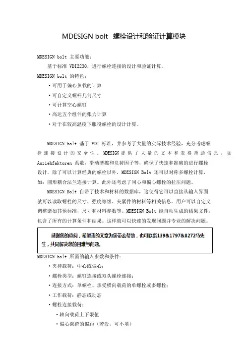
螺栓连接方式
·承载面外直径
·螺帽高度
·夹持件
·夹持件材料及力学性能(标准库自带)
·夹持件厚度
·垫圈
·是否考虑垫圈
·垫圈厚度
·垫圈材料及力学性能
·孔是否有加工槽
·平均粗糙度
·是否预估嵌入值
·是否预估载荷导入因子
·根据载荷类型的连接方式:SV1-SV6
·拧紧过程中使用的屈服点
·螺纹切削类型
MDESIGN bolt 标准的输出物:
见该链接。
MDESIGN bolt 标准库:
螺栓强度等级标准
螺栓类型
设计。除了可以计算经典的螺栓以外,MDESIGN Bolt 还可以对称多螺栓计算,
如:圆形耦合法兰连接计算。此外还考虑了同心和偏心螺栓的拉压问题。
MDESIGN Bolt 自带了技术和材料的数据库,这使得它可以直接从输入界面
就可以读取螺栓的尺寸、强度等级、夹紧件的材料等相关信息。用户可以自定义
调整诸如其他标准,尺寸和材料参数等。MDESIGN Bolt 能自动生成的结果文件,
螺栓扭矩和预紧力计算公式vdi2230
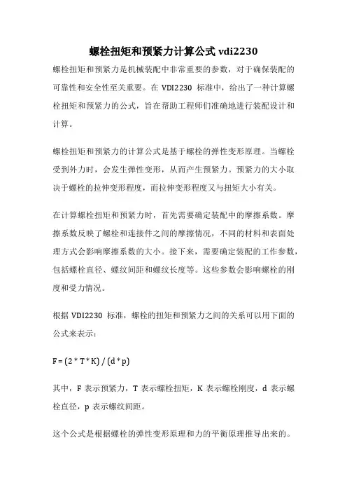
螺栓扭矩和预紧力计算公式vdi2230螺栓扭矩和预紧力是机械装配中非常重要的参数,对于确保装配的可靠性和安全性至关重要。
在VDI2230标准中,给出了一种计算螺栓扭矩和预紧力的公式,旨在帮助工程师们准确地进行装配设计和计算。
螺栓扭矩和预紧力的计算公式是基于螺栓的弹性变形原理。
当螺栓受到外力时,会发生弹性变形,从而产生预紧力。
预紧力的大小取决于螺栓的拉伸变形程度,而拉伸变形程度又与扭矩大小有关。
在计算螺栓扭矩和预紧力时,首先需要确定装配中的摩擦系数。
摩擦系数反映了螺栓和连接件之间的摩擦情况,不同的材料和表面处理方式会影响摩擦系数的大小。
接下来,需要确定装配的工作参数,包括螺栓直径、螺纹间距和螺纹长度等。
这些参数会影响螺栓的刚度和受力情况。
根据VDI2230标准,螺栓的扭矩和预紧力之间的关系可以用下面的公式来表示:F = (2 * T * K) / (d * p)其中,F表示预紧力,T表示螺栓扭矩,K表示螺栓刚度,d表示螺栓直径,p表示螺纹间距。
这个公式是根据螺栓的弹性变形原理和力的平衡原理推导出来的。
通过这个公式,我们可以根据给定的螺栓扭矩来计算出对应的预紧力。
反之,如果我们已知预紧力,也可以通过这个公式来计算出所需的螺栓扭矩。
需要注意的是,这个公式只适用于理想情况下的计算,即假设螺栓和连接件之间没有松动和失效等情况。
在实际应用中,还需要考虑其他因素,如材料的强度和刚度、连接件的松动等。
在实际的工程应用中,为了确保装配的可靠性和安全性,通常会根据实际情况对计算结果进行修正和调整。
这包括考虑螺栓和连接件的松动、温度变化等因素。
螺栓扭矩和预紧力的计算是机械装配设计中的关键步骤之一。
通过合理地计算和调整,可以确保装配的可靠性和安全性,提高机械设备的工作效率和寿命。
在实际应用中,需要根据具体情况进行综合考虑和分析,以得到最合理的装配设计方案。
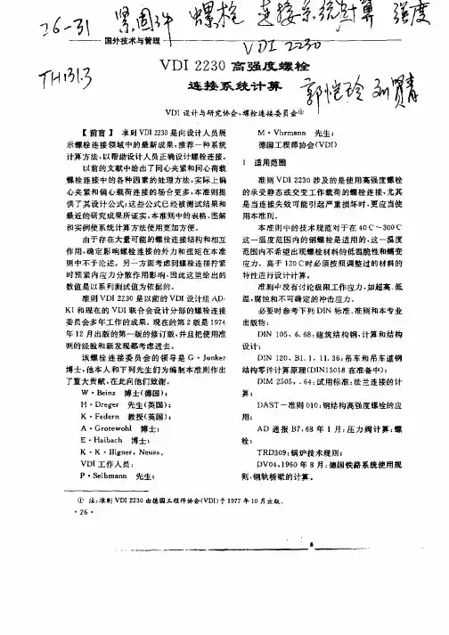
VDI2230高强度螺栓连接系统计算研究
且根据应力取决于夹 紧零件和被夹 紧零件的弹
性 回能 。因此 总 结 如下 :
Fs ^一 F^
() 2
() 3
F^ Fs + FP 一 ^ ^ FP = ( 一 ) ^ ^ 1 F
( ) 4
并且 :
F R F K = v— FP = Fv ( 一 ) ^ 一 1 F^ ( ) 5
— —
在 大端 轴承 盖 螺 栓 连 接 中, 受 往 复 承
活 塞发 动 机 的振 动 . 种 螺 栓 的 夹 紧 力 必 须 调 这
整得更高t 以保证 在其 内力作用下不会 出现接 合 面单 侧分 离或 打 滑 。这两 种情 况 都会 由于 螺
栓 连接 的 自动 卸开 或螺 栓 的疲 劳 失效 从 而 引起 逐 渐破坏 。 由于夹 紧力会 引起 受力 轴 承 套变 形 . 直 到它 们在 接 台 面 完 全停 止 转 动 一 此 夹 紧 力 因 应 该是 内部 压力 产 生的 工作 载荷 的许 多倍 。
一 一
螺 栓 的强 度级 别 ;
图2 普通情况轴向工作栽荷 F 连接 图 , 一
・
一
…
由于工作载荷引起连接体或者连接零
27 ・
国外技术与管理
。 _
交 变 载 荷疲 劳强 度 ;
\ 、 \ \
F 之 间( 见 4 6 2节 ) M 参 ..
~
螺 栓 头 部 或 螺母 引起 的被夹 紧零 件 的
的弹性变形产生了单个螺栓连接处的轴 向载荷
F 、 向力 F 、 一横 口 弯矩 M 以 及 有 时 存 在 的 扭 矩 Mr 由于结 构零 件 和螺检 连 接 的设 计 是多 种 多 。 样的・ 确定 这 些 基 本 变量 的载 荷 与变 形 分 析是 困 难 而又 复 杂 的 , 须 利用 静力 学和 弹性 力 学 必
关于VDI2230高强度螺栓系统计算的使用说明
关于使用VDI2230进行螺栓校核的说明1.通用说明R1. 确定拧紧系数拧紧系数与拧紧方式相关,不同的拧紧方式对应的拧紧系数范围不同。
如果有试验值,则用试验值,如果没有试验值,则根据拧紧方式取VDI2230表A8中拧紧系数范围的中值。
R2.摩擦系数、受力界面数的确定摩擦系数与被连接件的材料、表面处理方式有关。
q f , q m 取值根据连接件的受力方式而定,做一个图例数据库,采用图例说明。
并联或串联R3. 连接类型的确定根据受力情况而定,做一个图例数据库,采用图例说明。
sv1R4. 预紧力损失量VDI2230表中数值是对应屈服强度90%利用率的预紧力的损失量,如果初始预紧力低于这个许用最大预紧力(F M <F Mzul ),预紧力损失量取预紧力的10%。
设计给定的10%。
R7. 屈服强度的利用系数,螺纹最小摩擦系数μGmin屈服强度利用系数v 应根据试验而定,目前根据VDI 标准取0.9作为比较值。
设计提供的预紧力与最大装配预紧力必须要小于F Mzul 。
螺纹最小摩擦系数μG min 由查表得到,如果有试验值,则取试验值。
R8. 确定工作应力如果初始设计给的预紧力合格,则公式(th max max V A n Mzul s F F F F ∆-+=ϕ)中F Mzul 用设计给的预紧力,否则计算终止,或者给设计提建议,采用R6中计算得到的最大装配预紧力,然后使用该预紧力校核。
R9. 确定交变应力F SAO 和F SAU 为计算的轴向载荷乘以螺栓轴向载荷系数。
R10. 确定表面压力F SA为螺栓的轴向载荷,应在F A的基础上乘以螺栓轴向载荷系数,若F A<0,则F SA取零。
F V为设计提供的预紧力。
R11.最小连接长度标准件不用校核,非标准件和螺钉需要校核。
R12.抗滑移安全系数抗滑移安全系数暂时按标准取1.2,如果取1.2不通过,则另外考虑。
2.非高强度螺栓VDI方法校核注意事项需要根据设计给出的预紧力的数值进行校核,不能完全照搬VDI标准中的参数,主要考虑到VDI是针对高强度螺栓建立的,预紧力是按照屈服强度90%利用率定的。
VDI 2230 Blatt 1 - Schraubenberechnung Ausgabedatum 2015-11(中文版)
页码 3 3 5 6 19 20 20 25 26 27 28 29 29 29 39 39 39 42 55 55 55
VDI-产品和工艺设计学会(GPP)
产品开发和机0 第 1 部分 5.3 载荷系数和附加螺栓载荷 5.3.1 载荷系数和直到松开极限的附加螺栓载荷 5.3.2 在偏心加载的情况下松开极限的关系 5.3.3 松开连接的关系 5.4 预加载荷 5.4.1 最小夹紧载荷 5.4.2 预加载荷的变化 5.4.3 装配预加载荷和拧紧扭矩 5.4.4 液压无摩擦和无扭矩拧紧 5.4.5 最小装配预加载荷 5.5 应力和强度验证 5.5.1 装配应力 5.5.2 工作应力 5.5.3 交变应力 5.5.4 在螺栓头部和螺母支承面的表面压力 5.5.5 螺纹旋合长度 5.5.6 剪切载荷 6 提高螺栓连接工作可靠性的设计信息 6.1 螺栓连接的耐久性 6.2 螺栓连接的松弛 附录 A 附录 B 计算表 计算举例 63 63 67 70 71 71 71 75 83 84 84 84 87 92 96 97 102 106 106 108 109 130 171 171 171 171 172 175 175 176 179
FAab
偏心加载时松开极限轴向载荷 同心加载时松开极限轴向载荷
FAKa FB
偏心加载时,单侧边缘支承开始时的轴向载荷 在任何方向的连接工作载荷
VDI 2230 第 1 部分
-9-
符号 FK FKA FKab FKerf FKP FKQ FKR FM ΔFM FMm FM max
名称 夹紧载荷 松开极限时最小夹紧载荷 松开极限时夹紧载荷 用于密封功能、摩擦夹紧和防止分界面单侧松开所需的夹紧载 荷 确保密封功能的最小夹紧载荷 通过摩擦夹紧传递横向载荷和/或扭矩的最小夹紧载荷 在通过 FPA 卸载或加载时和在使用中嵌入后, 在分界面的残余夹 紧载荷 装配预加载荷 装配预加载荷 FM 与最小预加载荷 FM min 的差值 平均装配预加载荷 螺栓必须设计的最大装配预加载荷,以便在连接中产生和保持 所需夹紧载荷,尽管在操作期间的拧紧技术和预计嵌入缺乏精 确性 所需最小装配预加载荷; 在 FM max 作为在拧紧技术和最大摩擦中 缺乏精确性的结果时,可能出现的最小装配预加载荷 表 A1 到 A4(ν = 0.9)的装配预加载荷表列值 许用装配预加载荷 螺栓在 0.2%规定非比例伸长应力的装配预加载荷 螺母或内螺纹的脱扣力 螺栓螺纹脱扣力 自由加载螺栓螺纹的断裂力 夹紧部件加载变化的轴向载荷比例,附加板载荷 恢复损失 横向载荷,垂直于螺栓轴线的工作载荷或任何方向工作载荷 FB 的分量 许用螺栓支承压力 许用螺栓剪切力 限制滑动力 螺栓载荷
基于VDI2230标准的螺栓设计参数优化案例展示
基于VDI2230标准的螺栓设计参数优化案例展示在上一次的案例分析中,我们通过一个简单的螺栓连接设计与可靠性验证的案例出发,掌握了MDESIGN BOLT模块的基本操作。
而这一次,我将会在之前的案例的基础之上,通过对螺栓连接设计进行优化,来了解与掌握更多的MDESIGN BOLT模块的功能。
一、案例回顾我们先简单回顾一下上一个案例的工况信息以及计算分析结果。
从计算结果可以看出:⑴初选出的螺栓的许可装配预紧力大于螺栓连接所需要的最大装配预紧力;⑵抗屈服安全系数S F=1.16>1,满足抗屈服安全条件;⑶抗疲劳安全系数S D=18.44>1.2,远远满足交变应力安全条件;⑷抗压溃安全系数S pMK=1.19>1,S pBK=1.18>1,满足表面压强安全条件;⑸现有啮合长度m vorh=18mm大于最小有效啮合长度mges=9.9mm,满足最小啮合条件;⑹依据工况所提供的装配工艺(扭矩扳手拧紧法),所需的拧紧扭矩为109.23N*M;综上,针对此案例,根据MDESIGN BOLT模块的计算结果判定,初选所确定的螺栓能够满足预定的设计要求,具有良好的可靠性。
在进行螺栓连接设计的时候,往往需要从两个方面考虑设计的合理性:一方面是设计的螺栓连接能够在已知的工况下完成预设的功能,即不发生失效,具有足够的可靠性;另一方面是设计的螺栓连接不存在过大的功能冗余,即不存在在强度、材料上的过度设计,进而达到降低重量或成本的目的。
在上一个推送中,我们验证了初选所确定的螺栓能够满足预定的设计要求,具有良好的可靠性,但是否会存在过大的功能冗余呢?从上图中我们可以发现,螺栓所能承受的最大装配预紧力(红线),相比于螺栓所需的最大装配预紧力(绿线),大了40%左右。
根据经验,这种情况下往往会存在过大的功能冗余,即可以使用公称直径更小或是强度等级更低的螺栓进行连接,依旧能够保证螺栓连接的可靠性。
二、修改螺栓的公称直径考虑到螺栓连接需要从活塞杆中扩孔,那么是否可以选用公称直径更小的螺栓,减小扩孔的孔径,进而减小对活塞杆的强度的削弱呢?通过MDESIGN BOLT模块,我们只需修改一个输入参数即可验证以上想法。
海克斯康国标计算公式
海克斯康国标计算公式摘要:1.海克斯康国标计算公式概述2.海克斯康国标计算公式的计算方法3.海克斯康国标计算公式的应用领域4.海克斯康国标计算公式的优缺点分析正文:【海克斯康国标计算公式概述】海克斯康国标计算公式,是一种用于测量物体质量的计算公式,由海克斯康公司研发,为我国国家标准GB/T 15466-1995《动态计量检定规程》所收录。
该公式的优点在于计算简便,适用范围广泛,因此在我国各行业计量领域得到了广泛应用。
【海克斯康国标计算公式的计算方法】海克斯康国标计算公式如下:质量= 信号幅度/ 灵敏度其中,质量为待测物体的质量,单位为千克(kg);信号幅度为测量设备输出的信号幅度,单位为伏特(V);灵敏度为测量设备的灵敏度,单位为伏特/千克(V/kg)。
【海克斯康国标计算公式的应用领域】海克斯康国标计算公式广泛应用于以下领域:1.工业生产:用于测量传送带上的物料质量,以保证生产过程的准确性和效率。
2.物流运输:用于测量货物的重量,以确保货物的准确运输和交付。
3.商品零售:用于测量商场、超市等场所的商品重量,以确保交易公平。
4.科学研究:用于测量实验样品的质量,以保证实验数据的准确性。
【海克斯康国标计算公式的优缺点分析】优点:1.计算简单,易于操作,适合各类人员使用。
2.适用范围广泛,可应用于各种质量测量场景。
3.精度高,可满足大部分计量要求。
缺点:1.受测量设备性能影响较大,设备精度直接影响计算结果。
2.测量过程中可能受到环境因素的干扰,如温度、湿度等。
3.对于特殊材料或物体,计算结果可能存在偏差。
总之,海克斯康国标计算公式作为一种广泛应用于我国计量领域的质量计算方法,具有计算简便、适用范围广泛等优点,但也存在一定的局限性。
VDI 2230计算例题
VDI 2230计算例题讲解主要内容和目的本部分主要通过介绍VDI 2230中附录B 实例B1的计算过程让大家对VDI 2230的计算方法有初步的认识、了解VDI 2230计算的基本步骤和方法,然后演示一个商业软件对该例题的计算,给大家今后的应用提供一种思路和办法。
一、VDI 2230例题B11.1初始条件:图示螺栓连接作为一个中心受力连接的计算例题主要尺寸:液压缸内压力2m ax /5.5mm N p =。
承压面积2222245364/)2580(4/)(mm D D A St Z =⋅-=⋅-=ππ。
轴向载荷kN A p F A 9.2445365.5m ax m ax =⨯=⋅=。
活塞是一个产生压力的零件,每小时300个工作冲程。
因此轴向载荷可以看作是一个动载荷。
由于螺栓还要有密封的作用,因而在不受载荷的情况下,还应该保持不少于NF KR 3m in 10=,以保证安全。
活塞材料为16MnCr5,活塞杆材料为C45。
表面粗糙度m R Z μ16=。
连接扭紧时使用能够指示扭矩的扳手。
1.2计算步骤R0 初步确定螺栓公称直径,核算其适用范围由表A7,对于集中作用的动载荷N F A 3m ax 109.24⋅=及0=Q F ,螺栓的直径可以按以下的步骤进行:表7A 确定螺栓的直径范围A 取N F 25000=作为仅次于max A F 的最大比较载荷。
B2 对于集中作用的轴向动载荷,取最小装配预紧力N F M 40000m in =。
C 用指示扭矩的扳手扭紧,取最大装配预紧力N F M 63000m ax =。
D 由表A7第2列,选择尺寸为M12的螺栓,其性能等级为12.9,为的是减小对活塞杆截面的削弱。
选择圆柱螺栓ISO4762-M12⨯60-12.9(GB 70.1-2000修改等同该标准)得到以下尺寸。
R1扭紧系数按采用的扭紧工具(显示扭矩的扳手),扭紧系数按表A8确定,对摩擦因数为B 级, 扭紧系数αA =1.7R2确定所需最小的夹紧力这一连接是中心对称的(0=sym S ,见P34,图5.1/5 b )而且在中心加载(a =0,见P34,图5.1/5 a )。
- 1、下载文档前请自行甄别文档内容的完整性,平台不提供额外的编辑、内容补充、找答案等附加服务。
- 2、"仅部分预览"的文档,不可在线预览部分如存在完整性等问题,可反馈申请退款(可完整预览的文档不适用该条件!)。
- 3、如文档侵犯您的权益,请联系客服反馈,我们会尽快为您处理(人工客服工作时间:9:00-18:30)。
Calculation of Screws According to VDI 2230, Edition 2003With this program you can carry out predimensioning of the nominal screw diameter (extended version only) as well as the system calculation of cylindrical screw-in joints according to VDI 2230, sheet 1,edition of 2003.The whole calculation process involving force and deformation relations is based on the screw-in joint model. I.e. all dimensions and loads influencing the complete junction from the outside are to be reducedto a screw-in joint and are presumed as known.You can calculate multiscrew joints, such as e.g. circular ring joint flanges. At that, you must take into account, that the angular momentum applied to the perimeter has been considered using the number of screws on the pitch circle and the resultant loads have been considered for each screw separately.In addition, you can take into account centric and eccentric tightenings/loadings.Besides, this calculation program has at its disposal technology files which enable you to read screw dimensions, different strength classes and materials of tightened parts directly into the entry page.All data base tables can be customized to the user (e.g. other standards).Extreme working loads, e.g. corrosion or impact loads can not be taken into account.Calculation BaseThe calculation base of the module Calculation of Screws is founded on VDI 2230, sheet 1, edition of February 2003 "Systematische Berechnung hochbeanspruchter Schraubenverbindungen Zylindrische Einschraubenverbindungen" (System Calculation of High-loaded Screw Joints, Cylindrical Single-screw joints).The fixed tightening force FM of the screw is considered at that as the main selection criterion of the nominal screw diameter.The following DIN standards have been used, too:- DIN EN ISO 4017 Issue of March 2001 Sechskantschrauben mit Gewinde bis Kopf (malehexagon screws threaded to head)- DIN EN ISO 8676 Issue of March 2001 Sechskantschrauben mit Gewinde bis Kopf undmetrischem Feingewinde (male hexagon screwsthreaded to head with metric fine thread)- DIN EN ISO 4014 Issue of March 2001 Sechskantschrauben mit Schaft (male hexagon screwswith body)- DIN EN ISO 8765 Issue of March 2001 Sechskantschrauben mit Schaft und metrischemFeingewinde (male hexagon screws with body andmetric fine thread)- DIN EN ISO 4762 Issue of February 1998 Zylinderschrauben mit Innensechskant (cylindricalscrews with inner hexagon)- DIN EN ISO 4032 Issue of March 2001 Sechskantmuttern, Typ 1 (female hexagon screws,type 1)- DIN EN ISO 8673 Issue of March 2001 Sechskantmuttern, Typ 1, mit metrischem Feingewinde(female hexagon screws, type 1, with metric finethread)- DIN EN ISO 7089 Issue of November 2000 Flache Scheiben, Normale Reihe, Produktklasse A (Flatwashers, standard series, product class A)- DIN EN 20 273 Issue of February 1992 Durchgangslöcher für Schrauben (through holes ofscrews)- DIN 13 T1-10 Issue of November 1999 Metrisches ISO-Gewinde (metric ISO thread)- DIN EN 10269 Issue of November 1999 Stähle und Nickellegierungen für Befestigungselementebei erhöhten Temperaturen (steels and nickel alloys forfastening elements at higher temperature values)- DIN EN ISO 3506-1 Issue of March 1998 Mechanische Eigenschaften von Verbindungselementenaus nichtrost. Stählen (stress-strain properties ofconnectives made of stainless steels)- DIN 267-13 Issue of August 1993 Mechanische Verbindungselemente (mechanicallyconnected elements)- DIN EN ISO 898-1 Issue of November 1999 Mechanische Eigenschaften von Verbindungselementenaus Kohlenstoff –und legiertem Stahl (stress-strainproperties of connectives made of carbon and alloyedsteel)Special returns:- VDI-returns No. 1644, 2001 Schraubenverbindungen (screw joints)LimitationsThe calculation steps are valid for steel screws having the fastening thread with a flank angle of 60°. Service loads can be given as statically or dynamically acting axial forces. In addition, transverse forcesand service moments can be provided, too.All loads effecting the joint and the results connected with them are related only to a single-screw joint.The dimension of the juncture area in the level "screw axis - effect line of the working force" is limited bythe so-called measure G.The elastic flexibility of the tightened parts is presumed as linear variable. I.e., if the axial working force exceeds the separation force, the flexibility increases progressively and there is a loose connection,which can not be calculated by this program.Principally, working temperatures for the screw and the joint parts can be considered as explicitdepending on the material choice in the range of –270°C ≤ T≤ 700°C.Notice:All standard data bank records are stored from +20°C and depending on the chosen material till maximal 600°C!The jar washers can be also taken into account during the calculation. It is presumed then, that on thenut side and on the head side the dimensions and the materials are the same.Calculation of Screws - Formulae Symbols and TermsInputCalculation of Screws – Defining ResultsPredimensioning of the Nominal Screw Diameter, Calculation Process "Entwurf" ("Project")The calculation process "Entwurf" ("Project") enables predimensioning the nominal screw diameter using a minimum of input parameters.The definition of the nominal diameter is carried out depending on a chosen strength class according to the table A7 given in the supplement A of VDI 2230. Strength classes 8.8, 10.9 and 12.9 are there at your disposal.The following table is the calculation basis:Defining the appropriate diameter range is carried out in many sections sketched as follows:1. The next larger force for the given maximal axial force FAO is chosen in the column 1. If an additional maximal transverse force FQ and FA0 < (FQ) / (m Tmin) is specified, FQmax is used only.2. The required minimal preload force ensures, if the following number of steps (strings) continues from the above-named value:- at the fixed value according to FQmax:4 steps at choosing static or dynamic working load- at the fixed value according to FAO:2 steps for dynamically and eccentrically acting axial force1 step for dynamically and centrically or statically and eccentrically acting axial forceno step for static and centrically acting axial force3. The maximal tolerable minimal preload force ensures, if you continue the following number of steps (strings) from this value again:2 steps for tightening the screw using an impact screwdriver1 step for the torque-controlled tightening methodno step for the over-elastic yield-stress-controlled or rotation-angle-controlled tighteningmethod4. The defined value determines after choosing one of three strength classes (columns 2 - 4)the required nominal screw diameter. Besides the diameter, further geometric dimensions dependingon the screw type are shown in the result output. When switching to "Nachrechnung" (Recalculation)the done input values are automatically taken in.Notice:Depending on the working steps shown above the load acting on the juncture can be specified ina range from 250 N up to 630 N!Defining Results of the Calculation Process "Nachrechnung" (Recalculation)Calculation or Identification of the Eccentric Tightening ConditionsBasically, the eccentricity ssym in this program can be taken into account in two ways. At that, the eccentricity can also take on negative values!After specifying the dimensions of the juncture area the eccentricity is defined automatically using the following equation:In addition, the distance from the edge of the separation point of the centroidal axis 0-0 is calculated, too:At the second possibility the parameters ssym and u are to be specified by the user. At that, regulating signs is carried out choosing the appropriate three variants (tension/pressureloading).The distance ssym is positive, if the line of action of the axial working strength and the screw axis lie related to the axis of the deformable members (Axis 0-0) on the same side. If the line of action of the axial working strength and the screw axis lie on the contrary side, the distance ssym is negative.The distance from the edge u, is positive, if the separation point lies relative to the axis 0-0 on the side facing the force, and negative on the appropriate contrary side.Clamping Length lK [mm]For n tightened parts including perhaps jar washers with the thickness hs it is valid at passing screw joints (DSV):For screw-in joints (ESV) with perhaps sink depth ts of the screw-in part is valid:Limit Value G [mm]The limit value G defines the maximal possible juncture dimension in the plane screw axis line of action of the axial working strength at eccentrically tightened joints. It is designated by the length cT.At exceeding the limit value the specified calculation bases are no more valid. Although the program continues calculating you must be aware of a more critical calculation error.For DSV with the smallest plate thickness hmin is valid:At ESV:with counter-bored washer seat in the screw-in partThe main requirement is:bzw.Tightening Factor a A [-]The tightening factor describes the scatter of the assembly pretension load between FMmin and FMmax. Then, depending on the choice of the tightening method it is automatically transferred to the calculation or it is specified by the user by means of "free entering". For more details see also the help text on the input page under Tightening Method!Areal Moment of Inertia in the Juncture IBT [mm^4]Required Minimal Tracking Force Fkerf [N]Defining the required minimal tracking force Fkerf is carried out considering the following main requirements:Minimal Tracking Force of Transmitting a Transverse Force and/or a Torque FKQ [N]At single-screw joints with shear load and FQ as the input value:At multiscrew joints:With the radius of friction ra,we have:Sealing Against a Medium FKP [N]Prevention of an One-sided Separation FKA [N]The required minimal tracking force Fkerf ensures now from the appropriate largest value of the above-mentioned main conditions:Elastic Flexibility of the Screw d S [mm/N]The elastic flexibility of the screw is calculated adding the cylindrical elements taken separately:Notice:If the working temperature is deflecting from the indoor temperature, it is taken into account when calculating with the modulus of elasticity corresponding with the appropriate temperature!Compliance of the Screw Head d SK [mm/N]With the nominal cross-section:Compliance of the Body of Screw d i [mm/N]The compliance of the screw body area is calculated from the sum of the partial lengths. The appropriate cross-section area is considered as follows:body screws with the length l1thinned body screws with the length l2withsmallest suitable body cross-section at "own screw geometry"Compliance of the Free Loaded Thread Part d Gew [mm/N]For body or thinned body screwsFor screws threaded up to headFor screws from "own screw geometry"With the root cross-section:Compliance of the Screw-in Thread Area d GM [mm/N]At DSV with:andAt ESV with the modulus of elasticity EM of the last defined tightened part:andAngle of the Equivalent Deformable Cone j [Grad]Screw-in joints (ESV) with dimensions of the deformable members in the range of:and ,are considered during defining the elastic compliance of the tightened parts as passing screw joints (DSV).For ESV:For DSV:Limit Diameter of the Deformable Cone DAGr [mm]Constant:Cone Height lV [mm]Bush Height lH [mm]Outer Diameter of the Truncated Cone dwi [mm]Starting with the diameter dw of the bearing surface area of the screw head or of the nut the bearing area diameter of the partial deformable cone j is calculated using:Compliance of the Deformable Cone d PV [mm/N]If it is DA≥ DAGr, the deformation model at DSV consists only of two and at ESV only of one equivalent deformable cone.Compliance of the Deformable Bush d PHi [mm/N]If it is DA≤ dw, the deformation model consists only of one deformable bush.Elastic Flexibility of the Centrically Tightened Parts d P [mm/N]If it is dw < DA < DAGr, the equivalent deformable member consists of a cone (or cones) and a bush. Using the above-mentioned partial compliances it is calculated via the appropriate addition of the general compliance to:Notice:If the working temperature is deflecting from the indoor temperature, it is taken into account when calculating using the modulus of elasticity corresponding with the appropriate temperature.The separation, what tightened part belongs to the deformable cone or to the deformable bush,is carried out by program loop automatically.Equivalent Areal Moment of Inertia of a Partial Deformable Cone IBersVi [mm^4]Equivalent Areal Moment of Inertia of an Eccentrically Tightened Partial Deformable Cone IBersVei [mm^4]Equivalent Areal Moment of Inertia of a Partial Deformable Bush IBersHi [mm^4]Elastic Flexibility of Eccentrically Tightened Parts d*p [mm/N]Elastic Flexibility at Eccentric Tightening and Loading d**p [mm/N]Notice:If the working temperature is deflecting from the indoor temperature, it is taken into account when calculating with the modulus of elasticity corresponding with the appropriate temperature.The separation, what tightened part belongs to the deformable cone or to the deformable bush,is carried out by program loop automatically.Force Delivery Factor n [-]If it is not preset by the user in a range of 0 < n≤ 1 the force delivery factor n is defined automatically after the juncture types SV1-SV6 as well as the distances lA, ak and the height h were chosen. At that, the height h, the clamping area between screw head and nut or screw-in section is set by the program automatically.Here, the basis is the table 5.2/1 given in VDI 2230 of Oct. 2001, p. 27. Values lying among the tabular data are defined through linear interpolation.Notice:at centric loading (a = 0), the distance is lA = 0!Force Ratio F [-]Depending on the set type of loading and tightening different force ratios are resulting.In what follows different force ratios are listed:Centrically loaded and centrically tightened, with n = 1Centrically loaded and centrically tightened, with n < 1Centrically loaded and eccentrically tightened, with n = 1Centrically loaded and eccentrically tightened, with n < 1Special case: loading only through an extern working torque MBEccentrically loaded and centrically tightened, with n = 1Eccentrically loaded and centrically tightened, with n < 1Eccentrically loaded and eccentrically tightened, with n = 1Eccentrically loaded and eccentrically tightened, with n < 1Notice:The force ratio is represented in the detail equations without Indices, that is only by F! Shrinkage fz [m m]If there are no trial values to preset, the shrinkage fz can be calculated using this program. But it is presumed, that for a massive contact equal roughness are to be available on the joint surfaces. Besides, the shrinkage values defined by the program make sense only if the limit bearing stress has been not exceeded.The total shrinkage ensures through the appropriate synthesizing on basis of the following table:Notice:for more details see VDI 2230, issue of Oct. 2001, section 5.4.2.1.Preload Force Loss Owing to Shrinkage Fz [N]Owing to shrinkage of a screw joint to the value fz ensures the resulting preload force loss in the working regime to:Preload Force Change Owing to a Working Temperature not Equal to RT D F'Vth [N]Thermally Induced Preload Change D FVth [N]Allowable Assembly Pretension Load FMzul [N]The allowable assembly pretension load is calculated depending on the chosen screw type as follows:For set screws and screws threaded to headDeterminative diameterDeterminative cross-sectionFor screws with compliant bodyDeterminative diameterDeterminative cross-sectionFor screws from "own screw geometry"Choosing "own screw geometry" it is possible to define the screw body area with up to 9 pitch cylinders. At first, the basis is here the smallest diameter dimin of maximal 9 pitch cylinders.The determinative diameter is defined according to the following assumption:If or , thenIf , thenDeterminative cross-sectionFor torsion-free screw-tightening for stability factor proof is valid:Notice:The pure assembly pretension load is available only after the mounting at room temperature was finished. Hence, the values of FMzul are always corresponding with those of the indoortemperature!Minimal Preload Force FVmin [N]If D FVth < 0 you may set D FVth = 0 into the equation. The thermally induced preload change is considered only at D FVth > 0!Axial Force on the Separation Limit FAab [N]At centric loading and tighteningAt an eccentric loadWorking Torque on the Separation Border MBab [Nm]Checking the Linear Loading Process [-]The modulus Calculation of Screws is based on the calculation principles of the linear loading process, which is available in the strict sense only at non-separating joints. If the axial working strength exceeds the separation force, the screw joint starts to separate one-sided. Though the program goes on calculating, a precise definition of the force and deformation action is impossible. You must be aware of a larger calculation error.Hence, the following is valid for the given program in general:Maximal Secondary Screw Force up to the Separation Limit FSAmax [N]For the special case with specifying a secondary working torque MB is valid:Maximal Secondary Plate Force up to the Separation Limit FPAmax [N]Notice:at tensile load (FAO > 0) the secondary plate force FPA is a part of the axial working strength, which unloads the tightened parts. At compression forces (FAO < 0) the tightened parts in thejoint are additionally loaded with FPA!Minimal Required Assembly Pretension Load FMmin [N]If D F'Vth < 0, you may set D F'Vth = 0 into the equation. The preload force change is considered only at D F'Vth > 0!Maximal Tolerable Assembly Pretension Load FMmax [N]The maximal tolerable assembly pretension load is calculated from the equation of the main dimensioning, which is the basis of the screw calculation, as follows:Notice:if the yield-stress-controlled or rotation-angle-controlled tightening method is chosen, the scatter of the assembly pretension load is not defined through tightening but through the yield stress ofthe mounted screws. To design the screw using FMmax is no longer relevant at that. Thetightening factor a A stays not considered, so that the screw is then dimensioned using FMmin! Checking the Allowable Screw dimension [-]The following condition must be fulfilled for a sufficiently dimensioned screw:Defining the Working Load in the Elastic ScopeThis calculation process is to carry out only if the axial working strength FAO and the usage factor of the yield stress n < 100% are preset.Maximal Total Tractive Effort of Screw in the Working Regime FSmax [N]If D FVth > 0, you may set D FVth = 0 into the equation. The thermally induced preload change is considered only at D FVth < 0!Thread Tightening Moment MG [Nmm]Maximal Tensile and Torsional Stress in the Working Regime s zmax, t max [N/mm²]For setscrews and screws threaded up to headDeterminative diameterDeterminative cross-sectionFor screws with the compliant bodyDeterminative diameterDeterminative cross-sectionPolar moment of resistanceFor screws from "own screw geometry"Choosing "own screw geometry" it is possible to define the screw body area with up to 9 pitch cylinders. The basis is here first of all the smallest diameter dimin of maximal 9 pitch cylinders.Standard diameter is determined by following assumption:If or , thenIf , thenDeterminative cross-sectionPolar moment of resistanceComparison Tension in the Operating Regime s redB [N/mm²]With the reduction coefficient:Safety Against Exceeding the Yield Stress SF [-]For torsio-free screw-tightening for stability factor proof is validNotice:if a working temperature of the screw Ts is specified, the appropriate thermal extension limit RpminT is taken as a basic one!Defining the Working Load in the Over-elastic RangeOn the assumption of the over-elastic tightening to be already available at n > 90%, the safety check of the working load is carried out as follows.Preload Force at Over-elastic Tightening FV1 [N]Using the upper value of the strengthening factor according to VDI 2230, p.42:Safety Check in the Over-elastic Range [-]Valid is:Cyclic Load at Dynamic Working LoadLimit Cycle Peak Value of the Screw s a or s ab [N/mm²]For concentric loading and clampingFor eccentric clamping and concentric loading:For concentric or eccentric clamping and eccentric loading, the following applies:Bending resilience for bolted joints with n clamped partsBending resilience of the bolt, in general:Moment of resistance of the stress cross section of the bolt threadAverage bolt load FSm [N]Stress amplitude of the endurance limit s A [N/mm²]The calculation procedure of the fatigue limit is carried out for N≥ 2 · 106 automatically, if not other was specified. Alternating cyclesFor bolt threads rolled before heat treatmentFor bolt threads rolled after heat treatmentSafety margin against fatigue failure SD [-]Depending on the calculation procedure, the following applies:Stress amplitude of the fatigue strength s AZ [N/mm²]For one thing, the calculation procedure within the fatigue strength range is carried out automatically, if the aforecited fatigue limit is not fulfilled or, in the second place, if the "Dynamic strength within the fatigue strength range" was activated by the user. In this case, only the calculation for the fatigue embodiment is performed. Then, the valid area for the number of alternating cycles is applied as follows:For bolt threads rolled before heat treatmentFor bolt threads rolled after heat treatmentSafety at fatigue strength SZ [-]Depending on the calculation procedure, the following applies:Calculation of the head and/or nut bearing area [mm²]Principally, you must distinguish between the head bearing area with or without washer. Besides, the chamfer diameter of the hole can be taken into account, additionally.In general, establishing the maximum inside diameter of the plane bearing area is carried out for:The parameter Da is the inside diameter of the plane nut bearing area (chamfer diameter of the nut). The minimum value corresponds with the nominal thread diameter d!Bearing area of the bolt headBearing area between the washer and the first clamped partWith the outside bearing area diameter for standardized washers:Similar to it, the analysis on the nut side, when selecting bolted joints (DSV), would be: Nut bearing areaBearing area between the washer and the last clamped partFor the outside bearing area diameter of the standardized washers:Maximum surface pressure in the assembly state with utilization of the yield point n < 100% [N/mm²]Depending on the aforecited calculation procedure (bonding technique, with/without washer), the appropriate bearing area is taken into account.Maximum surface pressure under bolt headMaximum surface pressure between the washer and the first clamped partMaximum surface pressure under the nut bearing areaMaximum surface pressure between the washer and the last clamped partMaximum preload FVmax [N]Maximum surface pressure in the working state with utilization of the yield point n < 100% [N/mm²]The calculation of the maximum surface pressure in the working state is omitted, if no any axial working load was specified.In general, the maximum surface pressure in the working state is calculated with the bearing area, similar to that at the assembly state, as follows:If D FVth > 0, in the equation D FVth = 0 is substituted. The thermally induced preload change is taken into account only at D FVth < 0!For joints loaded in compression (FAO < 0), FSAmax = 0 is substituted.Maximum surface pressure with utilization of the yield point n≥ 100% [N/mm²]For tightening beyond the elastic limit or selecting the yield-controlled and angle-controlled tightening, a distinction is no more made between the assembly and the working state when determining the surface pressure, but an appropriate maximum surface pressure is calculated on basis of the aforecited bearing areas.Limiting surface pressure pG [N/mm²]The determined maximum surface pressure may not exceed the limiting surface pressure of the appropriate material. When specifying a working temperature unequal RT, the changed tensile strength is underlying only in the working state or for tightening beyond the elastic limit. The limiting surface pressure for the assembly state is always based on the tensile strength at room temperature.Depending on the specified number and type of material of the clamped parts, the limiting surface pressure of the last defined part is calculated at DSV additionally.The limiting surface pressure is calculated by means of the influencing factor fG as well as the tensile strength of the material as follows:Limiting surface pressure of the washerLimiting surface pressure of the first clamped partLimiting surface pressure of the last clamped part (at DSV)Safety margin against exceeding the limiting surface pressure Sp [-]Depending on the calculation procedure, the following applies:Shearing strength of the thread piece or of the internal thread t BM [N/mm²]Determining the minimum length of engagement is carried out only when selecting "Tapped thread joints (ESV)", because we proceed from the fact, that the standardized nuts are utilized at the least with the strength grades according to the bolts and so they are capable of bearing full load. Thus, a proof of the minimum required length of engagement is omitted.The shearing strength is calculated on basis of the material of the tapped thread component. Because itis intended, that the last defined plate is a component with the internal thread, the material of the last clamped part is considered.Notice:If the working temperature deflects from the room temperature, this fact is taken into account in the appropriate heat-resistance when calculating the temperature.Available effective length of engagement mvorheff [mm]The available length of engagement concerns only the thread turns of bolt and of the internal thread which are completely in engagement.Therefore, the engagement area is reduced by a possible counterbore depth tS (already contained in the clamp length) as well as a thread chamfer for (d - d3) / 2 default.If , thenIf , thenShearing cross section of the internal thread ASGM [mm²]For the pitch diameter of the internal thread:Shearing cross section of the bolt thread ASGS [mm²]Strength ratio Rs [-]。