2011年国际数模资料 Evolution of Graphene Growth on Ni and Cu by Carbon Isotope Labeling
2011年美国大学生数学建模竞赛优秀作品
AbstractThis paper presents one case study to illustrate how probability distribution and genetic algorithm and geographical analysis of serial crime conducted within a geographic information system can assist crime investigation.Techniques are illustrated for predicting the location of future crimes and for determining the possible residence of offenders based on the geographical pattern of the existing crimes and quantitative method,which is PSO.It is found that such methods are relatively easy to implement within GIS given appropriate data but rely on many assumptions regarding offenders’behaviour.While some success has been achieved in applying the techniques it is concluded that the methods are essentially theory-less and lack evaluation.Future research into the evaluation of such methods and in the geographic behaviour of serial offenders is required in order to apply such methods to investigations with confidence in their reliability.1.IntroductionThis series of armed robberies occurred in Phoenix,Arizona between13September and5December1999and included35robberies of fast food restaurants,hotels and retail businesses.The offenders were named the“Supersonics”by the Phoenix Police Department Robbery Detail as the first two robberies were of Sonic Drive-In restaurants.After the35th robbery,the offenders appear to have desisted from their activity and at present the case remains unsolved.The MO was for the offenders to target businesses where they could easily gain entry,pull on a ski mask or bandanna, confront employees with a weapon,order them to the ground,empty the cash from a safe or cash register into a bag and flee on foot most likely to a vehicle waiting nearby. While it appears that the offenders occasionally worked alone or in pairs,the MO, weapons and witness descriptions tend to suggest a group of at least three offenders. The objective of the analysis was to use the geographic distribution of the crimes to predict the location of the next crime in an area that was small enough to be suitable for the Robbery Detail to conduct stakeouts and surveillance.After working with a popular crime analysis manual(Gottleib,Arenberg and Singh,1994)it was found that the prescribed method produced target areas so large that they were not operationally useful.However,the approach was attractive as it required only basic information and relied on simple statistical analysis.To identify areas that were more useful for the Robbery Detail,it was decided to use a similar approach combined with other measurable aspects of the spatial distribution of the crimes.As this was a“live”case, new crimes and information were integrated into the analysis as it came to hand.2.AssumptionIn order to modify the model existed,we apply serial new assumptions to the principle so that our rectified model can be much more practical.Below are the assumptions:1.C riminals prefer something about the locations where previous crimes werecommitted committed..We supposed the criminals have a greater opportunity to ran away if they choose to crime in the site they are familiar with.In addition,the criminals probably choose previous kill sites where their target potential victims live and work.2.Offenders regard it safer to crime in their previous kill site as time went by.This is true that the site would be severely monitored by police when a short term crime happened and consequently the criminal would suffer a risk of being arrested in that site.And as mentioned above ,the police would reduce the frequency of examining the previous kill sites as time went by.3.Criminals are likely to choose the site that have optimal distance .This is a reasonable assumption since it is probably insecure to crime in the site that stays far away and that costs an amount of energy to escape and adds the opportunity to be arrested in such an unfamiliar terrain.And it is also impossible to crime in the site nearby since it increases the probability of being recognized or being trapped.As a result,we can measure a optimal distance in series perpetrations.4.Crimes are committed by individual.We assume that all the case in the model are committed by individuals instead of by organized members.In this way the criminal is subject to the assumptions mentioned above due to his insufficient preparation.5.Criminals Criminals''movements unconstrained.Because of the difficulty of finding real-world distance data,we invoke the “Manhattan assumption”:There are enough streets and sidewalks in a sufficiently grid-like pattern that movements along real-world movement routes is the same as “straight-line”movement in a space be discrete into city blocks.It is demonstrated that across several types of serial crime,the Euclidean and Manhattan distances are essentially interchangeable in predicting anchor points.3.The prediction of the next crime site3.1The measure of the optimal distanceDue to the fact that the mental optimal distance of the criminal is related to whether he is a careful person or not,it is impossible for him to make a fixed constant.Besides,the optimal distance will change in different moment.However,such distance should be reflected on the distances of the former crime sites.Presume that the coordinates of the n crime sites is respectively ),(11y x 、),(22y x 、……、),(n n y x ,and define the distance between the th i crime site and the th j one as j D ,i .The distance above we first consider it as Euclid distance,which is:22,)()(j i j i j i y y x x D −+−=With that,we are able to measure the distance between the th n crime site and the th 1-n one respectively.According to the assumption 2,the criminal believes that the earlier crime sites have became saferfor him to commit a crime again,so we can define his mental optimal distance,giving the sites the weights from little to much according to when the offenses happened in time sequence,as:∑−==11,n i ni i D w SD Satisfying 121......−<<<n w w w ,111=∑−=n i i w .Presuming the th i crime happens in i t ,whichis measured by week,we can have ∑−==11n i i kk t t w .SD can reflect the criminal's mental condition to some extent,so we can use it to predict the mental optimal distance of the criminal in the th n 1+case.While referring to the th n crime site,the criminal is able to use SD to estimate the optimal distance in the next time,and while referring to the rest crime sites,the optimal distances reduce as time goes back.Thus,the optimal security of the th i crime site can be measured as the following:n ni i SD t t SD *=3.2The measure of the probability distributionGiven the crime sites and location,we can estimate tentatively the probability density distribution of the future crimes,which equals to that we add some small normal distribution to every scene of crime to produce a probability distribution estimate function.The small normal distribution uses the SD mentioned above as the mean,which is:∑=−−=n i i i SD r n y x f 122)2)(exp(211),(σσπi r is defined as the Euclid distance between the site to the th i crime site,and the standard difference of the deviation of the criminal's mental optimal distance is defined as σ,which also reflects the uncertainty of the deviation of the criminal's mental optimal distance,involves the impacts of many factors and can not be measured quantitatively.The discussion of the standard difference is as following:3.3The quantization of the standard differenceThe standard difference is identified according to the following goal,which is,every prediction of the next crime site according to the crime sites where the crimes were committed before should have the highest rate of success.When having to satisfying such optimization objective,it isimpossible to make the direct analysis and exhaustivity.Instead,we have to use the optimized solutions searching algorithm,which is genetic algorithm.\Figure1:The Distribution of the Population of the Last GenerationAccording to the figure,the population of the last generation is mostly concentrated near80, which is used as the standard distance and substituted to the*formula.With the*formula,we are able to predict the probability density of Whether the zones will be the next crime site.Case analysis:5crime site according to the4ones happened before Figure2:The prediction of theth6crime site according to the5ones happened before Figure3:The prediction of theth6crime site according to the5ones happened before Figure4:The prediction of thethAccording to the predictions happened before,the predictions of the outputs based on the models are accurate relatively,and they are able to be the references of the criminal investigations to some extent.However,when is frequency of such crime increases,the predictions of the outputs23crime site according deviated the actual sites more and more,such as the prediction of thethto the22ones happened before,which is:23crime site according to the22ones happened before Figure5:the prediction of thethConclusion according to analysis:It may not be able to predict the next crime site accurately if we use Euclid distance to measure the probability directly.So,we should analyze according to the actual related conditions.For example,we can consider the traffic commutes comprehensively based on the conveniences of the escapes,such as the facilities of the express ways network and the tunnels.According to the hidden security of the commitments,we should consider the population of the area and the distance from the police department.Thus,we should give more weights to the commute convenience,hidden security and less population.In addition,when the commitments increases,the accuracy of the model may decrease,resulted from the fact that when the criminal has more experience,he will choose the next crime sites more randomly.4.Problems and further improvementsWith23crimes in the series the predictions tended to provide large areas that included the target crime but were too large to be useful given the limited resources the police had at their disposal.At this stage,a more detailed look was taken at the directionality and distances between crimes.No significant trends could be found in the sequential distance between crimes so an attempt was made to better quantify the relationship between crimes in terms of directionality.The methodology began by calculating the geographic center of the existing crimes. The geographic center is a derived point that identifies the position at which the distance to each crime is minimized.For applications of the geographic center to crime analysis.Once constructed,the angle of each crime from the north point of the geographic center was calculated.From this it was possible to calculate the change indirection for the sequential crimes.It was found that the offenders were tending to pattern their crimes by switching direction away from the last crime.It appears that the offenders were trying to create a random pattern to avoid detection but unwittingly created a uniform pattern based upon their choice of locations.This relationship was quantified and a simple linear regression used to predict what the next direction would be.The analysis was once again applied to the data.While the area identified was reduced from previous versions and prioritized into sub-segments,the problem remained that the areas predicted were still too large to be used as more than a general guide to resource deployment.A major improvement to the methodology was to include individual targets.By this stage of the series,hotels and auto parts retailers had become the targets of choice.A geo-coded data set became available that allowed hotels and retail outlets to be plotted and compared to the predicted target areas.Ideally those businesses falling within the target areas could be prioritized as more likely targets.However,in some cases the distribution of the likely businesses appeared to contradict the area predicted.For example,few target hotels appeared in the target zone identified by the geographic analysis.In this case,more reliance was placed upon the location of individual targets. From this analysis it was possible to identify a prioritized list of individual commercial targets,which was of more use operationally.Maps were also provided to give an indication of target areas.Figure6demonstrates a map created using this methodology.It is apparent from the above discussion that the target areas identified were often too large to be used as more than a general guide by the Robbery Detail.However,by including the individual targets,it was possible to restrict the possible target areas to smaller,more useful areas,and a few prioritized targets.However,such an approach has the danger of being overly restrictive and it is not the purpose of the analysis to restrict police operations but to suggest priorities.This problem was somewhat dealt with by involving investigators in the analysis and presenting the results in an objective manner,such that investigators could make their own judgments about the results.To be more confident in using this kind of analysis a stronger theoretical background to the methods is required.What has been applied here is to simply exploit the spatial relationships in the information available without considering what the connection is to the actual behaviour of the offenders.For example,what is the reason behind a particular trend observed in the distance between crimes?Why would such a trend be expected between crimes that occur on different days and possibly involve different individuals?While some consideration was given to identifying the reason behind the pattern of directionality and while it seems reasonable to expect offender’s to look for freeway access,such reasoning has tended to follow the analysis rather than substantiate it.Without a theoretical background the analysis rests only on untested statistical relationships that do not provide an answer to the basic question:why this pattern?So next we will apply a quantitative method,which is PSO,based on a theoretical background,to locate the residence of the criminal's residence.5.The prediction of the residenceParticle Swarm Optimization is a evolutionary computation,invented by Dr.Eberhart and Dr.Kennedy.It is a tool of optimization based on iteration,resulted from the research on the behaviors of the bird predation.Initiating a series of random number,the PSO is able to catch the optimization with iteration.Like PSO,the resolution of our residence search problem is the criminal,whose serial crime sites have been abstracted into 23particles without volume and weight and extended to the 2-D space.Like bird,the criminal is presumed to go directly home when he committed a crime.So,there are 23criminals who commit the crimes in the 23sites mention before and then they will go home directly.The criminals are defined as a vector,so are their speed.All criminals have a fittness decided by the optimized functions,and every of them has a according speed which can decide their direction and distance.All the criminals know the best position (pbest,defined as the residence known by the individual),which has been discovered so far,and where they are now.Besides,every criminals also know the best position which has been found by the group (gbest,defined as the residence known by the group).Such search can be regarded as the experience of other criminals.The criminals are able to locate the residence by the experience of itself and the whole criminals.PSO computation initiates the 23criminals and then the offenders will pursue the optimized one to search in the space.In other words,they find the optimized solutions by iteration.Presume that in the 2-D space the location and speed of the ith crime site is relatively ),(2,1,i i i x x X =and ),(2,1,i i i v v V =.In every iteration,the criminals will pursue the two best positions to update themselves.The two best positions are relatively the individual peak (pbest),),(2,1,i i i p p P =,which is found by the criminal himself,and the group optimized solution (gbest),g P ,which has been found to be the optimized solution by the whole group so far.When the criminals found the two optimized solutions,they will update their speed and new position based on the following formulas.2,1),1()()1()]([)]([)()1(,,,,,22,,11,,=++=+−+−+=+j t v t x t x t x p r c t x p r c t wv t V j i j i j i j i j g j i j i j i j i In the above,the w is inertial weighted factor,21c andc are positive learning factors,21r andr are random number which are distributed uniformly between 0and 1.The learning factor can make the criminals have self-conclude ability and ability of learning from others.Here we make both of them be 2,as what they always are in PSO.The inertial weighted factor w decides the extent of the inheritance of the current speed of the crime sites.The appropriate choice can make them have balanced searching and exploring ability.For balancing the global searching ability and the local improving ability of the criminal in the PSO algorithm,here we adopt one of the self-adapted methods,which is Non-linear Dynamic Inertial Weight Coefficient to choose the inertial weight.The expression is as following:⎪⎩⎪⎨⎧=≤−−−−>avg avg avg f f f f f f w w w f f w w ,))*((,minmin min max min max In the above,the max w and min w are defined respectively as the maximum and minimum of w,f means the current functional value of the criminal,and the avg f and min f respectively means the average value and minimum value of all the current criminals.In addition,the inertial weight will change automatically according to the objective value,which gives the name self-adapted method.When the final values,which are estimations of the criminal's residence,become consistent,it will make the inertial weight increase.When they become sparser,it will make the inertial weight decrease.In the meantime,referring to the criminals whose final values are worse than the average value,its according inertial weighted factor will become smaller,which protect the crime site.Oppositely,when referring to the criminals whose final values are better than the average value,its according inertial weighted factor will become bigger,which makes the criminal nearer to the searching zone.So now,with the PSO of Non-linear Dynamic Inertial Weight Coefficient,we can calculate the minimum value of22,)()(j j j i y y x x R −+−=,j=1,2,3 (23)In the above,j ,i R is the residence of the criminal.Thus,we have the output (x,y)as(2.368260870656715,3.031739124610613).We can see the residence in the figure 7.Figure7:The residence in the map6.ConclusionThis paper has presented one case study to illustrate how probability distribution and geographical analysis of serial crime conducted can assist crime investigation. Unfortunately,in the Supersonic armed robbery investigation the areas identified were too large to have been of much use to investigators.Further,because of the number of assumptions applied the method does not inspire enough confidence to dedicate resources to comparing its results to the enormous amount of suspect data collected on the case.While the target areas predicted tended to be large,the mapping of individual commercial targets appears to offer a significant improvement to the method.However,as they stand,these methods lack a theoretical basis that would allow the results to be judged and applied in investigations.Limitations such as these can be offset to some degree by the involvement of investigators in the analysis.In the end,we used a quantitative method to locate the residence of the criminal to make the identified areas smaller.So,due to the advantages and drawbacks of the above methods,we suggest that we should use different methods to help us fight again the crimes comprehensively.。
2011数学建模国赛A题优秀获奖论文

我们参赛选择的题号是(从 A/B/C/D 中选择一项填写) : 我们的参赛报名号为(如果赛区设置报名号的话) : 所属学校(请填写完整的全名) : 参赛队员 (打印并签名) :1. 2. 3. 指导教师或指导教师组负责人 (打印并签名): 日期: 2012 西安电子科技大学 欧阳照玮 李娟 王小磊
A
r ( h)
符号解释 变异函数 块金常数 拱高
3
C0
C1
RMSPE
Pi Ci Si
P综
均方根预测误差 重金属 i 的污染指数 污染物 i 的实测含量 污染物二级参考标准值 内梅罗综合污染指数 重金属浓度标准化后的可观测指标 公共因子 因子载荷 污染物浓度随时间变化量 空间域内污染物通过的流量 空间域内污染物的增量 污染源释放的重金属总量 扩散影响半径
2011 高教社杯全国大学生数学建模竞赛
承
诺
书
我们仔细阅读了中国大学生数学建模竞赛的竞赛规则. 我们完全明白,在竞赛开始后参赛队员不能以任何方式(包括电话、电子邮 件、网上咨询等)与队外的任何人(包括指导教师)研究、讨论与赛题有关的问 题。 我们知道,抄袭别人的成果是违反竞赛规则的, 如果引用别人的成果或其他 公开的资料(包括网上查到的资料) ,必须按照规定的参考文献的表述方式在正 文引用处和参考文献中明确列出。 我们郑重承诺,严格遵守竞赛规则,以保证竞赛的公正、公平性。如有违反 竞赛规则的行为,我们将受到严肃处理。
年 8 月 9日
赛区评阅编号(由赛区组委会评阅前进行编号):
2011 高教社杯全国大学生数学建模竞赛
编 号 专 用 页
赛区评阅编号(由赛区组委会评阅前进行编号):
赛区评阅记录(可供赛区评阅时使用): 评 阅 人 评 分 备 注
Materials and Manufacturing Processes-2011-649
This article was downloaded by: [East China University of Science and Technology]On: 23 November 2012, At: 00:44Publisher: Taylor & FrancisInforma Ltd Registered in England and Wales Registered Number: 1072954 Registered office: Mortimer House, 37-41 Mortimer Street, London W1T 3JH, UKMaterials and Manufacturing ProcessesPublication details, including instructions for authors and subscription information:/loi/lmmp20Mullite Fibers Prepared by Sol-Gel Method UsingAluminum Chloride Aluminum Isopropoxide andTetraethylorthosilicateYabin Zhang a , Yaping Ding a , Yong Li a , Jiqiang Gao a , Jianfeng Yang a & Litong Guo ba State Key Laboratory for Mechanical Behavior of Materials, Xi'an Jiaotong University, Xi'an,Chinab Material Science and Engineering College, China University of Mining and T echnology,Xuzhou, ChinaVersion of record first published: 22 Apr 2011.PLEASE SCROLL DOWN FOR ARTICLEMaterials and Manufacturing Processes ,26:649–653,2011Copyright ©Taylor &Francis Group,LLC ISSN:1042-6914print/1532-2475online DOI:10.1080/10426910903124787Mullite Fibers Prepared by Sol-Gel Method Using Aluminum Chloride Aluminum Isopropoxide and TetraethylorthosilicateYabin Zhang 1,Yaping Ding 1,Yong Li 1,Jiqiang Gao 1,Jianfeng Yang 1,and Litong Guo 21State Key Laboratory for Mechanical Behavior of Materials,Xi’an Jiaotong University,Xi’an,China 2Material Science and Engineering College,China University of Mining and Technology,Xuzhou,ChinaMullite fibers with good flexibility were prepared from an aqueous water solution of aluminum chloride (AC),aluminum isopropoxide (AIP),tetraethylorthosilicate (TEOS)by the sol-gel process.Aluminosilicate spinnable sol (pH =2)with the stoichiometric mullite composition Al:Si =3:1 AIP/AC =2:1 was prepared.The removal of organic and chlorine was completed at 800 C.The complete transformation to mullite was observed at 1200 C by X-ray diffraction (XRD).The lateral and circumferential cracks were showed in the results of scanning electron microscopy (SEM)when fibers were sintered at 10 C min −1.It was useful for preparation of fibers with smooth surface and uniform diameter by controlling the sintering schedule.Keywords AlCl 3·6H 2O;Drying;Fiber;Mullite;Process;Reaction;Sintering;Sol-gel.IntroductionMullite fibers were used widely for their excellent high-temperature strength,creep resistance,thermal and chemical stability,low thermal expansion coefficient,and good dielectric properties [1–6].They are mainly used as reinforcement of metals or ceramics and as high-temperature or electrical insulating materials.Conventionally,ceramic fibers are prepared by drawing the melt through the orifice at high temperature [7,8].This method makes the raw materials to a homogeneous high melt with certain viscosity.However,it is difficult to prepare the fibers with high melting points of start materials.The sol-gel technique applied to fiber preparation overcomes the difficulties [9–13].The sol is hydrolyzed and then condensed or polymerized at certain temperature until an appropriate viscosity for spinning is achieved for the production of fipared to high temperature melt,the sol-gel method not only makes the start materials homogeneous,but also lowers the sintering temperature because of its fine grains and homogeneous composting.Some successful methods for preparing mullite fibers by the sol-gel method have been reported.Ki Chang Song [14,15]prepared the mullite fiber with the aluminum isopropoxide (AIP),aluminum nitrate,tetraethylorthosilicate (TEOS).Kiyoshi Okada et al.studied the effect of different Al source on the mullite fiber [16]and found some cracks due to decomposition of nitrates.Long cracks along the fiber axis were also seen.In most of starting materials,aluminum nitrate was selected as Al source [14–18]because of its good solubility in water or ethanol.However,the decomposition of nitrate took placeReceived March 2,2009;Accepted June 2,2009Address correspondence to Yabin Zhang,State Key Laboratory for Mechanical Behavior of Materials,Xi’an Jiaotong University,Xi’an 710049,China;E-mail:zhyab@when mixing solution was condensed to sol using a water bath,resulting into the formation of bubbles of yellowish nitrogen-dioxide gas.Consequently,the spinnability of sol was influenced by the microbubbles,although mullite fibers with smooth surface and uniform diameter were obtained finally.In this work,mullite fibers with smooth surface and no cracks were fabricated from using water solvent system of AlCl 3·6H 2O (AC),AIP,and TEOS.The process of mullite fibers,including rheological behavior and viscosity of sol,drying temperature,drying time,and sintering schedule are presented in this article.ExperimentalAluminosilicate gel with the stoichiometric mullite composition Al:Si =3:1 was prepared as follows.An aqueous solution of AC (Chemical grade,Xi’an reagent factory,Xi’an,China)and AIP (chemical grade,Shanghai chemical reagent Co.Ltd.,Shanghai,China)was used as an alumina source,and AIP/AC in molar ratio was 2:1.The silicon was introduced by the TEOS (chemical grade,Xi’an reagent factory,Xi’an,China).AC was dissolved into distilled water at room temperature with vigorously stirring for 0.5h.A solution with a pH value of 2was obtained.Then TEOS was added to the solution further stirring for 1h.The value of TEOS/H 2O was 1:3in volume ratio.To this solution,AIP was added slowly with vigorously stirring at 80 C.The distilled water was added into the solution with stirring until the solution was transparent.The solution was condensed at around 80 C using a water bath.After appropriate condensation of the solution,the viscosity of solution with a pH value of 1was suitable for spinning.Subsequently,gel fibers were drawn at room temperature 25 C by a hand drawing method.The gel fibers were then dried around 10minutes at 40 C.The dried fibers were sintered in air at different temperature at the rate of 5 C and 10 C.649D o w n l o a d e d b y [E a s t C h i n a U n i v e r s i t y o f S c i e n c e a n d T e c h n o l o g y ] a t 00:44 23 N o v e m b e r 2012650Y.ZHANG ET AL.Rheological measurement and viscosity measurement of as-prepared and spinning sols were carried out by using a NDJ-1viscometer (Shanghai Balance Tech.Co.,Ltd.,Shanghai,China)at room temperature at different shear rate (6rmin −1,12rmin −1,30rmin −1,and 60rmin −1 .The average values of viscosity at different shear rate were calculated.The prepared fibers were characterized by Fourier transform infrared (FTIR)spectroscopy,thermo-gravimetric analysis/differential scanning calorimetry (TG/DSC),X-ray diffraction (XRD),and scanning electron microscopy (SEM).The FTIR spectroscopy was detected on Prestige-21(Shimadzu,Tokyo,Japan).The TG/DSC was measured on SDT Q600(TA,USA)with a heating rate 10 C min −1and sample weights about 15mg.The XRD patterns were obtained on D/max-3c diffractometer (Rigaku Co.,Ltd.,Japan)at 40kV and 100mA using Cu K radiation,a step width of 0 02 and a counting time of 0.3s.The SEM observation was done on JSM-35C instrument (JEOL,Japan).Results and discussionThe effect of time in 80 C water bath on viscosity of sol is presented in Fig.1(a).The viscosity of as-prepared sol was about 150mPa ·s.It increased with time when it was condensed in 80 C water bath.The sol viscosity increased slowly before 1000mPa ·s,and it was considered that AIP and TEOS was hydrolyzed and condensed slowly according to Eqs.(1)and (2),and the fiber length was only 2–4cm at this time.Subsequently,water evaporation took place accompanied with chemical reaction until the sol viscosity was up to 1600mPa ·s.The spinning fibers length was an excess of 20cm,which was due to the good spinnability of sol.However,the spinnability of sol became worse when the sol viscosity increased to 3000mPa ·s,while fiber length was short and fibers diameter was asymmetric.This could be explained by the condensation reaction among hydroxyl groups and formation of Si-O-Si and Al-O-Al oxide network because of the polymerization of raw materials [19–23].The dehydration reactions can occur not only between molecules (intermolecular self-condensation)but also within one molecule (intramolecular self-condensation)according to Eqs.(3)–(6).Figure 1(b)shows the rheological behavior of spinning sol which was bathed at 80 C for 105minutes.It can be seen that the shear rate had no effect on sol viscosity.The spinning sol behaved as Newtonian fluid at 80 C water bath aged for 105minutes.It could be attributed to the large amount of linear polymers rather than network structures included in Newtonian flow.The sol viscosity was influenced by the quantity and length of linear polymers.Thus the sol that behaved like Newtonian fluid showed good spinnability,whereas the sol that included large amounts of network structures showed badspinnability.Figure 1.—Viscosity change (a)and flow behavior (b)of sol at 80 C using a water bath.D o w n l o a d e d b y [E a s t C h i n a U n i v e r s i t y o f S c i e n c e a n d T e c h n o l o g y ] a t 00:44 23 N o v e m b e r 2012MULLITE FIBERS PREPARED BY SOL-GEL METHOD651Figure 2.—FTIR spectra of spinnable sol.The spinnable sol was also studied through FTIR analysis in the wave number region of 4000–400cm −1,as shown in Fig.2.The absorption peak at 3415cm −1and 1635cm −1are assigned to the OH stretching and bending modes of water.The band at 1436cm −1corresponded to the stretching vibration of CH 2and CH 3from residual reaction products according to Eqs.(1)and (2).It may be noted that the bands assigned to Al-O and Si-O groups were in the region of 1200–400cm −1.The band appeared at 1080cm −1was attributed to the Si-O-Si stretching vibration of SiO 4.In addition,bands at 979cm −1and 600cm −1were observed,which were due to the Al-O-Al vibration.Figure 3shows the weight loss of fibers when dried at 40 C.The fibers lost the majority of their weight during the first 8minutes,which was chiefly attributed to the evaporating of solvent.Little change in weight can be seen above 10minutes.Figure 3.—The weight loss of fibers which were dried at 40C.Figure 4.—TG and DSC curves of mullite sol.Figure 4shows the TG and DSC curves of mullite sol.The mass decreased drastically up to 800 C,which was chiefly due to the removal of chlorine and the decomposition of organic materials.No peak before 100 C could be seen because water was evaporated partly during drying procedure.The endothermic peak at ∼200 C corresponded to combustion of organic materials.The small exothermic peak at around 770 C was considered as removal of residual chlorine [see Fig.4(b)].So the weight decreased quickly before 300 C and slowly between 300 C and 800 C.The total amount of weight loss was also around 60mass%before 800 C,while the mass of sol became almost constant above 800 C.A sharp exothermic peak was shown at about 980 C in the TG/DSC curves,which was assigned to crystallization of mullite.Figure 5shows the XRD patterns of mullite fiber sintered at 1000 C,1100 C,and 1200 C.The main phase insamplesFigure 5.—XRD patterns of mullite fiber sintered at different temperature.D o w n l o a d e d b y [E a s t C h i n a U n i v e r s i t y o f S c i e n c e a n d T e c h n o l o g y ] a t 00:44 23 N o v e m b e r 2012652Y.ZHANG ETAL.Figure 6.—SEM photograph of fibers sintered at 1200 C for 1h using different rate:(a)and (b)10 C min −1,(c)5 C min −1,and (d)fibers showed flexibility.sintered at 1000 C was mullite phase.An amorphous phase was simultaneously observed at 1000 C,which was considered as the amorphous SiO 2and Al 2O 3(see the endothermic peak at ∼1000 C as shown in Fig.3).The mullite peaks showed higher intensity at 1100 C than 1000 C.It was shown that large amount of mullite phase was formed and amorphous phase plete transformation to mullite was observed at 1200 C.The mixing scale of Al and Si components was considered to be the factor that affected the mullization temperature.The mixing of Al and Si at molecular level was helpful to low transformation temperature,and the fiber achieved complete mullization temperature at 1200 C.Martin Schmücker et al.[24]explained the mullite grain microstructure developed from mosaic-type to facetted at the first stage of mullization.According to their conclusions,the grain growth exponent increased with firing temperature.So fiber mullization was remarkably slow between 1000 C and 1100 C,and subsequently grain growth exponent increased until the complete mullization at 1200 C.Figure 6shows the SEM photograph of fiber sintered at 1200 C for 1h using different rate.The diameter of sintered fibers was 20–40 m whereas average diameter of green fibers was 100 m.It showed the diameter shrinkage of the fibers was up to 50%at least,which corresponds well with the weigh loss observed in the TG curve.Figures 6(a)and (b)shows the fibers which were sintered at 10 C min −1.Figure 6(a)shows the lateral cracks running to the elongated direction of the fiber and circumferential cracks.Because of the fast drying and sintering speed of fibers,the amount of evaporation inside the fiber was different from that around fiber surface.So cracks occurred when fibers were sintered,which was due to the different expansion coefficient.Fibers after sintering showed surfaceroughness,as shown in Fig.6(b).As mentioned in the TG/DSC curve,evaporation of Cl −ions and removal of organic lead to rough surface of fibers.Although Cl −ions began to evaporate at ∼650 C,minor amounts of Cl −were present in the fibers when the fibers were calcined up to 1100 C [25].Chlorine as hydrochloric acid was removed when mullization transformation developed,which result in the rough surface.The sintered fibers at 5 C min −1were showed in Fig.6(c).It was showed that the fibers had uniform diameter and smooth surface.Defects were not found on the surface of fiber.The fiber which was sintered at 1200 C showed good flexibility,as shown in Fig.6(d).ConclusionsMullite fibers with good flexibility were prepared by sol-gel method using AC,AIP,and TEOS as start materials.The total amount of weight loss was also around 50mass%,whereas the diameter shrinkage of the fibers was also 50%at least.Spinnability was good when the sol included linear polymers,and Newtonian flow was obtained when viscosity was up to 1000mPa ·plete transformation to mullite was achieved at 1200 teral and circumferential cracks were found when fibers were sintered at 10 C min −1.However,it showed uniform diameter and smooth surface with no defects on the fiber surface when fibers were sintered at 5 C min −1slowly.The fiber also showed good flexibility when it was sintered at 1200 C.References1.Kanka,B.;Schneider,H.Aluminosilicate fiber/mullite matrix composites with favorable high-temperature properties.Journal of the European Ceramic Society 2000,20,619–623.2.Kaya,C.;Butler,E.G.;Selcuk,A.;Boccaccini,A.R.;Lewis,M.H.Mullite (Nextel™720)fibre-reinforced mullite matrix compositesD o w n l o a d e d b y [E a s t C h i n a U n i v e r s i t y o f S c i e n c e a n d T e c h n o l o g y ] a t 00:44 23 N o v e m b e r 2012MULLITE FIBERS PREPARED BY SOL-GEL METHOD653exhibiting favourable thermomechanical properties.Journal of the European Ceramic Society 2002,22,2333–2342.3.Boccaccini,A.R.;Atiq,S.;Boccaccini,D.N.;Dlouhy,I.;Kaya,C.Fracture behaviour of mullite fibre reinforced–mullite matrix composites under quasi-static and ballistic impact posites Science and Technology 2005,65,325–333.4.Deléglise, F.;Berger,M.H.;Bunsell, A.R.Microstructural evolution under load and high temperature deformation mechanisms of a mullite/alumina fibre.Journal of the European Ceramic Society 2002,22,1501–1512.5.Kriven,W.M.;Palko,J.W.;Sinogeikin,S.;Bass,J.D.;Sayir,A.;Brunauer,G.;Boysen,H.;Frey, F.;Schneider,J.High-temperature single crystal properties of mullite.Journal of the European Ceramic Society 1999,19,2529–2541.6.Mileiko,S.T.Single crystalline oxide fibres for heat-resistant posites Science and Technology 2005,65(15–16),2500–2513.7.Pan,W.;Li,R.T.Crystallization kinetics of the aluminum silicate glass fiber.Materials Science and Engineering A-Structure 1999,271(1–2),298–305.8.Bunsell,A.R.;Berger,M.H.Fine diameter ceramic fibres.Journal of the European Ceramic Society 2000,20(13),2249–2260.9.Yoon,W.;Sarin,P.;Kriven,W.M.Growth of textured mullite fibers using a quadrupole lamp furnace.Journal of the European Ceramic Society 2008,28(2),455–463.10.Venkatesh,R.;Chakrabarty,P.K.;Siladitya,Chatterjee,B.M.;Ganguli, D.Preparation of alumina fibre mats by a sol-gel spinning technique.Ceramics International 1999,25(6),539–543.11.Chatterjee,M.;Naskar,M.K.;Chakrabarty,P.K.;Ganguli,D.Sol-gel alumina fibre mats for high-temperature applications.Materials Letters 2002,57(1),87–93.12.Gotoh,Y.;Fujimura,K.;Ohkoshi,Y.;Nagura,M.;Akamatsu,K.;Deki,S.Preparation of transparent alumina film and fiber from a composite of aluminum polynuclear complex/methyl cellulose.Materials Chemistry and Physics 2004,83(1),54–59.13.Chandradass,J.;Balasubramanian,M.Effect of magnesium oxide on sol–gel spun alumina and alumina–zirconia fibres.Journal of the European Ceramic Society 2006,26(13),2611–2617.14.Song,K.C.Preparation of mullite fibers from aluminumisopropoxide–aluminum nitrate–tetraethylorthosilicate solutions by sol–gel method.Materials Letters 1998,35(5–6),290–296.15.Song,K.C.Preparation of mullite fibers by the sol-gel method.Journal of Sol-Gel Science and Technology 1998,13(1–3),1017–1021.16.Okada,K.;Yasohama,S.;Hayashi,S.;Yasumori,A.Sol-gelsynthesis of mullite long fibres from water solvent systems.Journal of the European Ceramic Society 1998,18(13),1879–1884.17.Chen,X.T.;Gu,L.X.The sol-gel transition of mullite spinningsolution in relation to the formation of ceramic fibers.Journal of Sol-Gel Science and Technology 2008,46(1),23–32.18.Chen,X.T.;Gu,L.X.Effect of solid content on formation ofsol-gel derived mullite fibres.Materials Science and Technology 2008,24(10),1179–1182.19.Rüdiger,S.;Eltanany,G.;Gro ß,U.;Kemnitz,E.Real sol-gelsynthesis of catalytically active aluminium fluoride.Journal of Sol-Gel Science and Technology 2007,41(3),299–311.20.Akihiko,M.;Hui, C.;Kazuo,T.;Michael,G.;Klaus,U.Novel route in the synthesis of MCM-41containing framework aluminum and its characterization.Microporous and Mesoporous Materials 1999,32(1–2),55–62.21.Hossein,A.D.;Mohammadsadegh,Y.;Burtron,H.D.An XRDand fourier-transformed infrared spectroscopy investigation of single and mixed -alumina and thorium oxide.Journal of Molecular Catalysis A:Chemical 2005,238(1–2),72–77.22.Sungseen, C.;Boyoung, C.;Seunggoo L.;Sungwook,L.;Sungsoon,I.;Seonghun,K.;Jongkyoo,P.Titania-doped silica fibers prepared by electrospinning and sol-gel process.Journal of Sol-Gel Science and Technology 2004,30(3),215–221.23.Masashi,I.;Minoru,K.;Tomoyuki,I.Alkoxyalumoxanes.Chemistry of Materials 2000,12(1),55–61.24.Marin,S.;Hartmut,S.;Thomas,M.;Bernd,C.Temperature-dependent evolution of grain growth in mullite fibres.Journal of the European Ceramic Society 2005,25(14),3249–3256.25.Ramanan,V.;Sutapa,R.R.Effect of organic additives on theproperties of sol-gel spun alumina fibres.Journal of the European Ceramic Society 2000,20(14–15),2543–2549.D o w n l o a d e d b y [E a s t C h i n a U n i v e r s i t y o f S c i e n c e a n d T e c h n o l o g y ] a t 00:44 23 N o v e m b e r 2012。
2011年美赛真题优秀论文
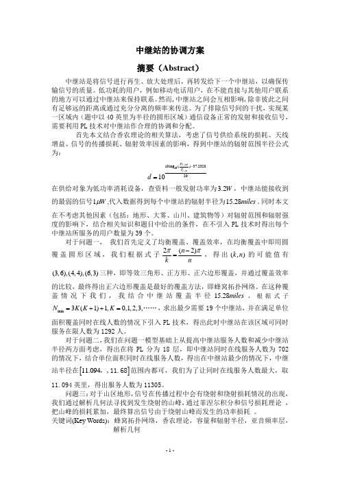
中继站的协调方案摘要(Abstract )中继站是将信号进行再生、放大处理后,再转发给下一个中继站,以确保传输信号的质量。
低功耗的用户,例如移动电话用户,在不能直接与其他用户联系的地方可以通过中继站来保持联系。
然而,中继站之间会互相影响,除非彼此之间有足够远的距离或通过充分分离的频率来传送。
为了排除信号间的干扰,实现某一区域内(题中以40英里为半径的圆形区域)通信设备正常的发射和接收信号,需要利用PL 技术对中继站作合理的协调和分配。
首先本文结合香农理论的相关算法,考虑了信号供给系统的损耗、天线增益、信号的传播损耗、辐射效率因素的影响,得到中继站的辐射范围半径公式为:,10,10log ()37.23282010r outr inp P d -=在供给对象为低功率消耗设备,查资料一般发射功率为3.2W ,中继站能接收到的最弱的信号1W μ,代入数据得到每个中继站的辐射半径为15.28m iles 。
同时本文在不考虑其他因素(包括:地形、大雾、山川、建筑物等)对辐射范围和辐射强度的影响下,结合相关知识和题目中给出的条件,在不引入PL 技术时得出每个中继站所服务的用户数量为39个。
对于问题一, 我们首先定义了均衡覆盖、覆盖效率,在均衡覆盖中即用圆覆盖圆形区域,我们根据式子2(2)n k n ππ-=,得出(,)k n 的可能值有(3,6),(4,4),三种,即等效三角形、正方形、正六边形覆盖,并通过覆盖效率的比较,最终得出正六边形覆盖是最好的覆盖方法,即蜂窝拓扑网络。
在这种覆盖情况下我们,我结合中继站覆盖半径15.28m iles ,根据式子m i n 3(1)1,0,1,2,3,N K K K =++=……,求出最少需要19个中继站,并在满足单位面积覆盖同时在线人数的情况下引入PL 技术,得出此时中继站在该区域可同时服务在限人数为1292人。
对于问题二,我们在问题一模型基础上从提高中继站服务人数和减少中继站半径两方面考虑,得出在将PL 分为18层,即中继站同时在线服务人数为702的情况下,结合单位面积同时在线服务人数,得出在中继站最少的情况下,中继站半径在[]11.094,,11.68范围内都可,我们为了让同时在线服务人数最大,取11.094英里,得出服务人数为11305。
2011全国数模竞赛A题

承诺书我们仔细阅读了中国大学生数学建模竞赛的竞赛规则.我们完全明白,在竞赛开始后参赛队员不能以任何方式(包括电话、电子邮件、网上咨询等)与队外的任何人(包括指导教师)研究、讨论与赛题有关的问题。
我们知道,抄袭别人的成果是违反竞赛规则的, 如果引用别人的成果或其他公开的资料(包括网上查到的资料),必须按照规定的参考文献的表述方式在正文引用处和参考文献中明确列出。
我们郑重承诺,严格遵守竞赛规则,以保证竞赛的公正、公平性。
如有违反竞赛规则的行为,我们将受到严肃处理。
我们参赛选择的题号是(从A/B/C/D中选择一项填写): A我们的参赛报名号为(如果赛区设置报名号的话): 20111663 所属学校(请填写完整的全名):南京邮电大学参赛队员 (打印并签名) :1. 刘超舟2. 刘立亿3. 董睿指导教师或指导教师组负责人 (打印并签名):日期: 2011 年 9 月12 日赛区评阅编号(由赛区组委会评阅前进行编号):编号专用页赛区评阅编号(由赛区组委会评阅前进行编号):全国统一编号(由赛区组委会送交全国前编号):全国评阅编号(由全国组委会评阅前进行编号):A题城市表层土壤重金属污染分析一.摘要二.问题重述三.符号约定四.基本假设五.建模与求解5.1问题(1)的建模与求解5.1.1问题分析根据采样的坐标,我们可以得到一个大概的区域分布散点图,如下图:图5.1.1 功能区采样点分布散点图图中各功能区得分布无规律,采样间隔比较大,很难建立各重金属测量值与样本采集点坐标的平滑函数,故采用等高线图来描述各种重金属在该城区的空间分布。
附件中给了采样点的三维坐标和各重金属元素的含量值,由于我们只需要考虑该区域的污染程度,因此不需要考虑坐标,只用知道采样地点位于某一区即可。
我们从采集样本的样本值中可以分析出每一区域的污染程度。
由于重金属分子的相对分子质量较大,取样时只对表层土壤0~10厘米深度进行取样,从收集的资料来看,可对取样值污染程度采用地积累指数分析法进行评级分析。
2011数学建模D题

天然肠衣搭配问题摘要本文研究的是天然肠衣搭配问题,目的是在满足规格要求的条件下,选择使成品捆数最多的优化方案。
共建立了3个模型。
对题中给出的要求逐个考虑,并运用Lingo和Matlab软件编程求解。
模型1 在给定一批原料的情况下,装出的成品捆数越多方案越好。
对各种不同规格的原料,根据每捆成品的总长度和根数建立整数规划模型,得出三种规格的最大捆数分别为14捆, 34捆,129捆。
总数量为177捆。
模型2 根据要求2,在模型1捆数最大的基础上,得出各规格捆数最大时的不同搭配方案,选出最优方案(详见表27,30,47)。
模型3 针对要求3,允许总长度有5.0的误差,各规格成品每捆的根数可以比标准少一根,明显条件放宽,可能会增加成品捆数。
运用Matlab和Lingo软件求解得到三种规格的捆数增加了6捆,总捆数为183捆,具体搭配方案见表48。
针对要求4,后一规格完成搭配后若材料有剩余,剩余材料可降级到前一规格使用,计算出三种规格的捆数增加3,最终最大捆数为186捆。
最后,选用合理的数据对模型进行模拟检验,把相应的数字输入流程,采用计算机搜索法,得出的方案时间不超过30分钟。
关键词:整数规划模型Lingo Matlab1 问题重述1.1 题目背景天然肠衣(以下简称肠衣)制作加工是我国的一个传统产业,出口量占世界首位。
肠衣经过清洗整理后被分割成长度不等的小段(原料),进入组装工序。
传统的生产方式依靠人工,边丈量原料长度边心算,将原材料按指定根数和总长度组装出成品(捆)。
1.2 题目条件1 原料按长度分档,通常以0.5米为一档,如:3-3.4米按3米计算,3.5米-3.9米按3.5米计算,其余的依此类推。
表1是几种常见成品的规格,长度单位为米,∞表示没有上限,但实际长度小于26米。
2 为了提高生产效率,公司计划改变组装工艺,先丈量所有原料,建立一个原料表。
表2为某批次原料描述(见附录A)。
1.3 题目要求1 对于给定的一批原料,装出的成品捆数越多越好;2 对于成品捆数相同的方案,最短长度最长的成品越多,方案越好;3 为提高原料使用率,总长度允许有± 0.5米的误差,总根数允许比标准少1根;4 某种规格对应原料如果出现剩余,可以降级使用。
2011年数学建模A题参考答案
城市表层土壤重金属污染分析摘要随着人们生活质量的提高和城市人口的增加,城市土壤的污染日益加剧。
通过对某城区土壤中的重金属元素含量的测定,分析污染情况。
根据所给数据,用MATLAB做出散点图及浓度的等值线图,找到各重金属元素的分布区。
然后,用单因子污染指数法和内梅罗综合污染指数法对采样地区土壤重金属污染程度作出分析,并根据重金属污染物的传播特征,利用聚类分析法建模,以确定污染源的位置。
重金属的分布在不同地区有所差异,并且距离污染源的位置越远其含量越少。
据此,用MATLAB作出浓度的等值线,即可看出As、Cd、Cr、Hg主要分布在工业区,Cu、Zn、Pb主要分布在主干道区。
用单因子污染指数法和内梅罗综合污染指数法,计算各元素的平均值与其环境背景值的比值,求得污染指数。
依据污染指数标准,可得污染程度由大到小依次为:工业区、主干道路区、生活区、公园绿地区、山区。
每个样品的重金属元素组成并不是独立、互不相干的,来自同一种源的成分之间存在较强的相关性。
因此可以通过主成分分析法缩减分析变量,找出主因子。
用SPSS进行因子分析,采用主成分分析法进行主因子的提取。
从输出数据中得到因子载荷量和累计贡献率,因子载荷量大的元素Cr,Ni,Cu,即为污染源的主要因素,累计贡献率大的为第一主因子,可代表主要污染源,即主要来源于工业污染和交通污染。
进入土壤中的重金属元素大部分通过渗透向外扩散(汞除外),从高浓度到底浓度,高海拔到低海拔逐层扩散。
重金属的分布在同一污染源周围有一定的规律,相似性高;不同的污染源在其周围的污染程度不同,相似性低。
所以通过对选取样本数据进行筛选,用聚类分析法分出相似性高的点,并求出其类中心,即求得各重金属的污染源。
考虑到地势、恶劣的气候、自然灾害、过度的获取地下水、重金属的污染、水环境的演化和人类工程活动等因素都对城市地质环境的演变产生不同的影响,收集以上相关数据,采用层次分析法,分析得出各因素对环境演变的主次关系,找到解决问题的途径。
2011数学建模c题

2011 高教社杯全国大学生数学建模竞赛承诺书我们仔细阅读了中国大学生数学建模竞赛的竞赛规则。
我们完全明白,在竞赛开始后参赛队员不能以任何方式(包括电话、电子邮件、网上咨询等)与队外的任何人(包括指导教师)研究、讨论与赛题有关的问题。
我们知道,抄袭别人的成果是违反竞赛规则的, 如果引用别人的成果或其他公开的资料(包括网上查到的资料),必须按照规定的参考文献的表述方式在正文引用处和参考文献中明确列出。
我们郑重承诺,严格遵守竞赛规则,以保证竞赛的公正、公平性。
如有违反竞赛规则的行为,我们将受到严肃处理。
我们参赛选择的题号是(从A/B/C/D 中选择一项填写): C我们的参赛报名号为(如果赛区设置报名号的话):sxxxxx所属学校(请填写完整的全名):xxx xxx xxx参赛队员(打印并签名) :1.2.3.指导教师或指导教师组负责人(打印并签名):日期: 2011 年9 月12 日赛区评阅编号(由赛区组委会评阅前进行编号):2011高教社杯全国大学生数学建模竞赛编号专用页赛区评阅编号(由赛区组委会评阅前进行编号):赛区评阅记录(可供赛区评阅时使用):全国统一编号(由赛区组委会送交全国前编号):全国评阅编号(由全国组委会评阅前进行编号):企业退休职工养老金制度的改革摘要针对企业退休职工养老金的改革问题,本文建立了差分阻滞模型模型以解决该类问题。
对于问题1,我们采用差分阻滞模型,先根据我国的经济发展战略目标和目前我国职工工资的实际发放情况以及现阶段中等发达国家的职工年平均工资,利用经验估计方法确定工资最大值T=20万元,再利用差值作图求出方程系数k ≈0.0000007,即求得差分方程式,最后利用方程式和matlab预测出的2011—2035年山东省职工历年平均工资与我国的国情基本吻合。
在此模型的检验图中我们可发现1978—2010年的工资预测值与实际值无太大差别。
对于问题2,先根据附件2求各年龄段职工工资与该企业平均工资之比作为职工缴费指数的参考值,再根据问题1中2011—2035年所预测的年平均工资、附件3中所给的养老金计算方法及个人账户养老金和本人指数化月平均缴费工资的计算公式,并利用matlab软件计算出6种情况下的养老金和养老金替代率。
- 1、下载文档前请自行甄别文档内容的完整性,平台不提供额外的编辑、内容补充、找答案等附加服务。
- 2、"仅部分预览"的文档,不可在线预览部分如存在完整性等问题,可反馈申请退款(可完整预览的文档不适用该条件!)。
- 3、如文档侵犯您的权益,请联系客服反馈,我们会尽快为您处理(人工客服工作时间:9:00-18:30)。
Evolution of Graphene Growth on Niand Cu by Carbon Isotope LabelingXuesong Li,†Weiwei Cai,†Luigi Colombo,*,‡and Rodney S.Ruoff*,†Department of Mechanical Engineering and the Texas Materials Institute,1Uni V ersityStation C2200,The Uni V ersity of Texas at Austin,Austin,Texas78712-0292,andTexas Instruments Incorporated,Dallas,Texas75243Received August3,2009ABSTRACTLarge-area graphene growth is required for the development and production of electronic devices.Recently,chemical vapor deposition(CVD) of hydrocarbons has shown some promise in growing large-area graphene or few-layer graphenefilms on metal substrates such as Ni and Cu.It has been proposed that CVD growth of graphene on Ni occurs by a C segregation or precipitation process whereas graphene on Cu grows by a surface adsorption process.Here we used carbon isotope labeling in conjunction with Raman spectroscopic mapping to track carbon during the growth process.The data clearly show that at high temperatures sequentially introduced isotopic carbon diffuses into the Nifirst,mixes,and then segregates and precipitates at the surface of Ni forming graphene and/or graphite with a uniform mixture of12C and 13C as determined by the peak position of the Raman G-band peak.On the other hand,graphene growth on Cu is clearly by surface adsorption where the spatial distribution of12C and13C follows the precursor time sequence and the linear growth rate ranges from about1to as high as6µm/min depending upon Cu grain orientation.This data is critical in guiding the graphene growth process as we try to achieve the highest quality graphene for electronic devices.Graphene,a monolayer of sp2-bonded carbon atoms or one monolayer of graphite,has attracted interest in part because of its unique transport properties.1The surface science community has published extensively on what is referred to as“monolayer graphite”,that is,graphene,as grown on various metalfilms that are epitaxially well matched to graphene.2To date,devices have been fabricated mostly on exfoliated graphene,1chemically reduced graphite oxide,3-6 graphene formed by ultrahigh vacuum(UHV)annealing of single crystal SiC,7,8and that grown on metal substrates.9-15 However,exfoliated graphene still shows superior transport properties compared to all other sources.Graphene obtained on SiC single crystals has good mobility,but this material may be limited to devices on SiC only,since transfer to other substrates such as SiO2/Si has not been demonstrated yet and might be difficult.There have been a number of reports on the growth of graphene on metal substrates such as Ni, Co,Ru,Ir,Cu,etc.,by UHV-chemical vapor deposition (CVD)9-11or“normal”CVD.12-15Because of cost,grain size,etchability,and their wide use and acceptance by the semiconductor industry,Ni and Cu have received the most attention as a graphene substrate material.Several groups have already demonstrated the growth of graphene and few-layer graphene(FLG)on polycrystalline Ni12-14while large area graphene has been grown on Cu15substrates by CVD. It has been proposed that CVD growth of graphene on Ni is due to a C segregation12or precipitation13process and that a fast cooling rate in conjunction with thinfilms are needed to suppress the formation of multiple graphene layers.12,14 But to date the graphenefilms grown on Ni foils or on Ni thinfilms have not yielded uniform graphene layers,that is, they have a wide variation in thickness over the metal surface from a monolayer to many layers.Recently,in a different publication,we have shown that Cu is an excellent candidate for making large-area graphenefilms with uniform thickness due to the low solubility of C in Cu.15In that publication it was suggested that the graphene growth is somehow surface mediated and self-limiting.In this work,we used isotopic labeling of the carbon precursor to study the mechanism and kinetics of CVD growth of graphene on Ni and Cu substrates.We took advantage of the separation of the12C and13C Raman modes to observe the spatial distribution of graphene domains.The frequencies of Raman modes are given by eq1with the assumption that the12C or13C atoms are randomly mixed and the bond force constants are equal16*To whom correspondence should be addressed.E-mail:(R.S.R.)r.ruoff@;(L.C.)colombo@.†The University of Texas at Austin.‡Texas Instruments Incorporated.ω)ω12 m12n12m12+n13m13(1)200912where ω12is the Raman mode frequency of 12C graphene/graphite,n 12and n 13are the atomic fractions,and m 12and m 13are the atomic masses of 12C and 13C,respectively.We used thin Ni film (∼700nm,deposited by sputtering on SiO 2/Si wafer)rather than on Ni foil to minimize the saturation time and the amount of carbon in the Ni film since the solubility of C in Ni is high,about ∼0.9at.%at 900°C.For Cu,we used foils having a thickness of 25µm since the carbon solubility is negligible.The experimental proce-dure for graphene growth is similar to that reported previ-ously 15with a deposition temperature of 900°C for Ni and 1000°C for Cu.However,in this work both normal methane and 13CH 4(99.95%pure)were introduced to the growth chamber in a specific sequence.The duration of exposure of methane is defined as j t i as,where j )12or 13denotes 12CH 4or 13CH 4,and i denotes the step in the sequence (e.g.,13t 1means the first gas introduced was 13CH 4with the duration of exposure being t 1).Figure 1shows schematically the possible distributions of 12C and 13C in graphene films based on different assumed growth mechanisms when 12CH 4or 13CH 4are introduced sequentially.We want to emphasize that “segregation”and “precipitation”should be distinguished as different concepts,which have been well explained by Shelton et al.,17that is,segregation refers to compositional heterogeneity in thermal equilibrium under conditions which correspond to a “one-phase”field,while precipitation refers to inhomogeneities that arise as a result of equilibrium “phase separation”.Blakely and coauthors have performed extensive studies on the formation of carbon films by cooling Ni foils saturated with C at high temperatures and found that a monolayer graphite grows first by C segregation,followed by more C precipitation thus forming graphite.17-20This previous work can be extended to explain CVD growth of FLG films on Ni film as well,as will be demonstrated in the following section.Figure 1a shows the case of carbon segregation from the bulk to the metal surface followed by precipitation growth.In the case of metals like Ni where the carbonsolubility is high,carbon diffuses into the metal first before segregating and precipitating to the surface.As a result,sequential dosing of 12CH 4and 13CH 4is expected to yield a uniform C-metal solution,and the segregated and/or pre-cipitated graphene will consist of randomly mixed isotopes (Figure 1a).In contrast,if carbon does not diffuse into the metal,graphene grown with the sequential dosing of 12CH 4and 13CH 4grows by surface adsorption and the isotope distribution in the local graphene regions will reflect the dosing sequence employed (Figure 1b).Figure 2shows the results of graphene growth on Ni film.We evaluated several sets of feeding time sequences of C isotopes on Ni films,but no distinguishable separation of isotopes was found.Figure 2a shows an optical micrograph of a graphene film grown on a Ni film (13t 1,3,5,7)12t 2,4,6,8)1min)and transferred onto a SiO 2/Si wafer by poly (methyl methacrylate)(PMMA)similar to the reported method.15,21The variation of color contrast indicates the film is not uniform in thickness and consists of one to tens of graphene layers.Figure 2b further shows the map of the G band and Figure 2c shows a typical Raman spectrum from this FLG film,which is located at ∼1553cm -1,corresponding to the composition of 45%-13C/55%-12C according to eq 1.The uniformity of the G-band and the uniform shift according to eq 1demonstrates the uniformity of the 12C and 13C distribution across the metal surface supporting the idea that the growth mechanism is as that described in Figure 1a.Figure 3shows the results of graphene grown on Cu foils (13t 1,3,5,7)12t 2,4,6,8)1min).Figure 3a shows an optical micrograph of the resulting graphene film transferred onto a SiO 2/Si substrate using PMMA as the carrier material for transfer as previously reported.15,21The surface of the transferred graphene is relatively uniform with the exception of wrinkles that are believed to be formed during cool-down.The wrinkles are a result of the different coefficient of thermal expansion between graphene/graphite and the un-derlying metal substrate.22,23Figure 1.Schematic diagrams of the possible distribution of C isotopes in graphene films based on different growth mechanisms for sequential input of C isotopes.(a)Graphene with randomly mixed isotopes such as might occur from surface segregation and/or precipitation.(b)Graphene with separated isotopes such as might occur by surfaceadsorption.Figure 2.Optical micrograph and distribution of C isotopes in a FLG film grown on Ni.(a)An optical micrograph of a FLG film transferred onto a SiO 2/Si wafer.(b)The corresponding Raman map of location of the G bands and (c)a typical Raman spectrum from this film,showing the film consists of randomly mixed isotopes (with an overall composition of ∼45%13C and ∼55%12C).Scale bars are 5µm.The Raman spectra,Figure 3b,show the presence of graphene with regions having close to pure 12C from natural methane (∼99%12CH 4),regions of isotopically pure 13C,and regions where both 12C and 13C are present.An analysis of both the color contrast of the optical micrograph,24and the Raman spectra 13,25-27show that the carbon layer is a monolayer of graphite,that is,graphene.When the Raman laser beam was focused at the junction of 12C and 13C graphene regions,the characteristic bands for both 12C and 13C graphene appeared in the spectrum.The intensity of each band depends on the area occupied by each isotopically labeled region under the laser spot and the sum of the intensity of two bands (e.g.,G 13+G 12)was found to be essentially equal to that of the intensity from either the pure 13C or 12C regions of the graphene film.Figures 3d -i shows the Raman G and D band maps of the graphene film shown in Figure 3a for both 12C and 13C.Figure 3d is a map of the overall G band intensity (G 13+G 12)of the area shown in Figure 3a.The uniform intensity distribution demonstrates that the thickness is uniform except for the wrinkles (bright lines).Figure 3e,f shows the mapsof the G-band of 13C and of 12C,respectively,which show the time evolution of graphene growth.The bright solid centers in the G 13map in Figure 3e correspond to 13C-graphene grown during 13t 1;the low intensity,dark rings correspond to 12C-graphene grown during 12t 2,which are seen as bright rings in the G 12map in Figure 2f;the bright area between the dark rings in Figure 3e corresponds to 13C-graphene grown during 13t 3.Figure 3c shows a line scan (marked with dashed lines across Figures 2d -f)where the 12C-graphene and 13C-graphene domains are clearly seen with the blue line representing the G 13(i.e.,13C-graphene)domains and the pink line representing the G 12(i.e.,12C-graphene)domains.The green line,which is the most uniform across the film,is the overall G band intensity (G 13+G 12)with the peak corresponding to the wrinkle in the film.It is interesting to note that we flowed eight cycles of alternating 12CH 4and 13CH 4but the resulting graphene grew only during the first three dosings.The fourth and subsequent doses played no role because the surface was already saturated with graphene.These data show that single layer graphene on Cu grows in less than 3min under the conditions weused,Figure 3.Micro-Raman characterization of the isotope-labeled graphene grown on Cu foil and transferred onto a SiO 2/Si wafer.(a)An optical micrograph of the identical region analyzed with micro-Raman spectroscopy.(b)Raman spectra from 12C-graphene (green),13C-graphene (blue),and the junction of 12C-and 13C-graphene (red),respectively,marked with the corresponded colored circles in (a)and (e).(c)Line scan of the dashed lines in (d -f).Integrated intensity Raman maps of (d)G 13+12(1500-1620cm -1),(e)G 13(1500-1560cm -1),(f)G 12(1560-1620cm -1),(g)D 13+12(1275-1375cm -1),(h)D 13(1275-1325cm -1),and (i)D 12(1325-1375cm -1)of the area shown in (a).Scale bars are 5µm.growth occurs in two-dimensions and thus is a consequence of a surface-adsorption process,and that growth is self-limiting since there is no catalyst to promote decomposition and growth after thefirst layer of carbon(graphene)is deposited.Thefilms grown on Cu show a nonuniform presence of the Raman D-band.The D maps in Figure3g-i provide additional information.Other than the high intensity of the D band from the wrinkles,some bright spots and lines are also seen corresponding to defective centers and boundaries between graphene domains,respectively.We define a domain as the area of graphene grown from one nucleus.The domain size will depend on the specific growth conditions and for the conditions used in this work the diameter of the domain is about10µm.The interdomain defects can occur where the graphene domains join,for example in the current case, after13t3,defects are observed as indicated by the blue arrows in Figure3g.The nature of the defects could be the formation of pentagonal and/or heptagonal arrangements of carbon atoms that form mis-oriented graphene domains resultingfrom the Cu surface roughness,as was found for Ir.28In contrast,the low defect boundaries(indicated by the white arrows in Figure3g)may indicate a“good”registration between two domains.A detailed understanding of such defects is suggested for future work.Careful observation of the optical micrograph(Figure3a)and the Raman maps (Figures3d-i)shows that there is no overlap of the graphene layers where the domains join,suggesting that there is crystallographic registration to the Cu substrate.If there were overlap,a high contrast or bright line would be present in the micrograph and the G-band Raman maps.This sequential distribution of13C and12C clearly shows that graphene growth on Cu is based on the surface adsorption mechanism. As we reported previously,15there can also be a small fraction of few-layerflakes stacked on the graphenefilm.For the samples discussed here,Raman imaging showed that these flakes also consist of separated13C and12C rings,indicating that they grow by surface adsorption,but not by segregation/ precipitation(Figure4).Theseflakes show the same or smaller number of isotopic sequential rings as thefirst layer graphene, indicating thatflake growth stops once the Cu surface is fully covered with graphene.Termination offlake growth due to the full coverage of Cu surface with graphene suggests that the carbon source forflake growth is from the catalytic decomposition of methane by the active Cu surface.Further work is necessary to understand the exact origin of theflake defects.We also studied the graphene growth rate from the growing front of either12CH4or13CH4.For the case of thefirst graphene layer,the edge growth rate for thefirst minute is3-6µm/min and for the second minute it is1-2µm/min.The growth rate is found to be dependent on the Cu grain orientation as was previously observed by scanning electron microscopy imaging of an interrupted growth runs.15The domain advancement rate that decrease with time could be associated with a decrease in the number of catalytic sites as the domainsfill the Cu surface area.This will require further investigation and the subject of a future publication.In contrast,the growth rate of the second and third layers is slower(<160and<40nm/min,respectively), and the multilayerflakes thus occupy a very small area(<5%) of the wholefilm.The slower growth rate of higher order layers may be attributed to a much lower concentration of Cu catalyst available to promote the decomposition of methane in these regions.The two mechanisms of graphene growth on Ni and Cu can be understood from the C-metal binary phase diagram.The binary phase diagrams of C-Ni and C-Cu are similar in that C has a limited solubility in the metal without the presence of a metal-carbide line compound.The only significant difference is that the solubility of C in Cu is much lower than that in Ni. Since only a small amount of carbon can be dissolved in Cu, the source for graphene formation is mainly from the CH4that is catalytically decomposed on the Cu surface with minimal carbon diffusion into the Cu.As mentioned previously,once the surface is fully covered with graphene growth terminates because of the absence of a catalyst to decompose CH4.In contrast,Ni can dissolve more carbon atoms and hence it is difficult to get uniform graphenefilms due to precipitation of extra C during the cool-down.The C precipitation process is a nonequilibrium process,which should be suppressed if one aims to achieve monolayer graphene growth,for example,by using a controlled thin Nifilm and/or high cooling rate.12-14However, because of microstructural defects,predominantly grain boundaries,it is very difficult to fully eliminate the effect of precipitation for metals with high carbon solubility.Hence, metals with low C solubility such as Cu offer a possible path to large-area growth of graphene.Discrete regions of isotopically labeled graphene such as presented here for growth on Cu may also yield novel devices and transport physics in future studies.Acknowledgment.We would like to thank the Nanoelec-tronic Research Initiative(NRI-SWAN;no.2006-NE-1464), the DARPA CERA Center,and The University of Texas at Austin forsupport.Figure4.Raman imaging spectroscopy of few-layer(FL)regions.(a)Optical micrograph.(b-d)Raman maps of overall G,G13,and G12,respectively,corresponding to the region in(a).The FL regions can be easily located from the optical micrograph due to their high contrast(a)and also from their high intensity in the overall G map (b).The layer and growth sequences are schematically shown in (e),where red,orange,yellow show13C grown in thefirst minute, blue,purple,teal show12C grown in the second minute,and maroon, lime show13C grown in the third minute.Scale bar is2µm.References(1)Geim,A.K.;Novoselov,K.S.Nat.Mater.2007,6(3),183–191.(2)Greber,T.[Online early access.]DOI:arXiv:0904.1520v1,2009.(3)Dikin,D.A.;Stankovich,S.;Zimney,E.J.;Piner,R.D.;Dommett,G.H.B.;Evmenenko,G.;Nguyen,S.T.;Ruoff,R.S.Nature2007,448(7152),457–460.(4)Gilje,S.;Han,S.;Wang,M.;Wang,K.L.;Kaner,R.B.Nano Lett.2007,7(11),3394–3398.(5)Stankovich,S.;Dikin,D.A.;Dommett,G.H.B.;Kohlhaas,K.M.;Zimney,E.J.;Stach,E.A.;Piner,R.D.;Nguyen,S.T.;Ruoff,R.S.Nature2006,442(7100),282–286.(6)Park,S.;Ruoff,R.S.Nat.Nanotechnol2009,4,217–224.(7)Berger,C.;Song,Z.;Li,X.;Wu,X.;Brown,N.;Naud,C.;Mayou,D.;Li,T.;Hass,J.;Marchenkov,a.A.N.;Conrad,E.H.;First,P.N.;de Heer,W.A.Science2006,312,1991–1996.(8)Emtsev,K.V.;Bostwick,A.;Horn,K.;Jobst,J.;Kellogg,G.L.;Ley,L.;McChesney,J.L.;Ohta,T.;Reshanov,S.A.;Rohrl,J.;Rotenberg,E.;Schmid,A.K.;Waldmann,D.;Weber,H.B.;Seyller,T.Nat.Mater.2009,8(3),203–207.(9)Marchini,S.;Gunther,S.;Wintterlin,J.Phys.Re V.B2007,76(7),075429.(10)Loginova,E.;Bartelt,N.C.;Feibelman,P.J.;McCarty,K.F.New J.Phys.2008,10,093026.(11)Sutter,P.W.;Flege,J.-I.;Sutter,E.A.Nat.Mater.2008,7,406–411.(12)Yu,Q.;Lian,J.;Siriponglert,S.;Li,H.;Chen,Y.P.;Pei,S.-S.Appl.Phys.Lett.2008,93,113103.(13)Reina, A.;Jia,X.;Ho,J.;Nezich, D.;Son,H.;Bulovic,V.;Dresselhaus,M.S.;Kong,J.Nano Lett.2009,9,30–35.(14)Kim,K.S.;Zhao,Y.;Jang,H.;Lee,S.Y.;Kim,J.M.;Kim,K.S.;Ahn,J.-H.;Kim,P.;Choi,J.-Y.;Hong,B.H.Nature2009,457,706–710.(15)Li,X.S.;Cai,W.W.;An,J.H.;Kim,S.;Nah,J.;Yang,D.X.;Piner,R.D.;Velamakanni,A.;Jung,I.;Tutuc,E.;Banerjee,S.K.;Colombo, L.;Ruoff,R.S.Science2009,324,1312.(16)Fan,S.;Liu,L.;Liu,M.Nanetechnology2003,14,1118–1123.(17)Shelton,J.C.;Patil,H.R.;Blakely,J.M.Surf.Sci.1974,43,493–520.(18)Isett,L.C.;Blakely,J.M.Surf.Sci.1976,58(2),397–414.(19)Eizenberg,M.;Blakely,J.M.Surf.Sci.1979,82(1),228–236.(20)Eizenberg,M.;Blakely,J.M.J.Chem.Phys.1979,71(8),3467–3477.(21)Reina,A.;Son,H.;Jiao,L.;Fan,B.;Dresselhaus,M.S.;Liu,Z.F.;Kong,J.J.Phys.Chem.C2008,112,17741–17744.(22)Cai,W.W.;Piner,R.D.;Stadermann,F.J.;Park,S.;Shaibat,M.A.;Ishii,Y.;Yang,D.X.;Velamakanni,A.;An,S.J.;Stoller,M.;An, J.H.;Chen,D.M.;Ruoff,R.S.Science2008,321(5897),1815–1817.(23)Obraztsov,A.N.;Obraztsova,E.A.;Tyurnina,A.V.;Zolotukhin,A.A.Carbon2007,45,2017–2021.(24)Ni,Z.H.;Wang,H.M.;Kasim,J.;Fan,H.M.;Yu,T.;Wu,Y.H.;Feng,Y.P.;Shen,Z.X.Nano Lett.2007,7(9),2758–2763. (25)Ferrari,A.C.;Meyer,J.C.;Scardaci,V.;Casiraghi,C.;Lazzeri,M.;Mauri,F.;Piscanec,S.;Jiang,D.;Novoselov,K.S.;Roth,S.;Geim,A.K.Phys.Re V.Lett.2006,97,187401.(26)Casiraghi,C.;Pisana,S.;Novoselov,K.S.;Geim,A.K.;Ferrari,A.C.Appl.Phys.Lett.2007,91,233108.(27)Das,A.;Pisana,S.;Chakraborty,B.;Piscanec,S.;Saha,S.K.;Waghmare,U.V.;Novoselov,K.S.;Krishnamurthy,H.R.;Geim,A.K.;Ferrari,A.C.;Sood,A.K.Nat.Nanotechnol.2008,3,210–215.(28)Coraux,J.;N’Diaye,A.T.;Busse,C.;Michely,T.Nano Lett.2008,8(2),565–570.NL902515K。