MP150系统软件和硬件使用说明书
GZ-MS150 摄像机 详细用户使用指南说明书
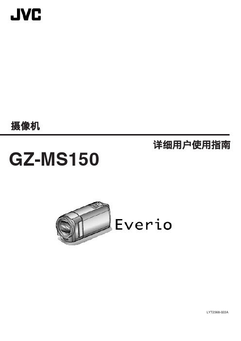
摄像机LYT2368-022A详细用户使用指南GZ-MS150目录表入门指南 (4)充电 (4)录制 (4)播放 (4)拍摄提示 (4)节假日/圣诞节 (5)婚礼 (6)旅行 (7)游乐园 (9)入门主要功能 (10)核对附件 (11)电池充电 (12)用USB电缆充电 (12)握带调整 (13)使用手带 (13)插入SD卡 (14)可以使用的SD卡类型 (14)使用Eye-Fi卡 (15)打开本机 (15)时钟设定 (16)重设时钟 (17)更改显示语言 (18)握住本机 (18)安装三脚架 (18)在海外使用本机 (19)在海外给电池充电 (19)旅行期间按当地时间设置时钟 (19)设置夏时制 (20)备选附件 (20)录制在智能自动模式下拍摄视频 (21)变焦 (23)手动录制 (23)场景选择 (24)手动调整聚焦 (25)调整亮度 (26)设置白平衡 (27)设置背光补偿 (28)拍摄特写镜头 (28)减轻相机振动 (29)清楚地捕抓人物(面部识别AE/AF) (30)间隔录制(延时录制) (31)通过感应动作自动录制(自动录制) (32)剩余录制时间/电池电量 (33)播放播放视频 (35)连接电视机并在电视机上观看 (37)经由AV接口连接 (37)编辑删除不需要的文件 (38)删除当前播放的文件 (38)删除选定的文件 (39)删除所有文件 (40)保护文件 (40)保护当前显示的文件 (40)保护所选文件 (41)保护所有文件 (42)取消所有文件的保护 (42)复制连接至DVD录像机或VCR来复录文件 (43)通过连接蓝光录像机刻录光盘 (43)复制到 Windows PC (44)核对系统要求(指引) (45)安装随附软件 (45)备份所有文件 (46)组织文件 (47)在不用随附软件的情况下备份文件 (48)文件和文件夹列表 (49)复制到Macintosh电脑 (49)菜单设定操作菜单 (51)录制菜单(视频) (52)脸部优先AE/AF (53)手动补偿 (53)增亮 (54)风声消除 (54)慢速录制 (54)自动录制 (54)视频质量 (55)变焦 (55)时钟设定 (55)手动设置菜单 (57)场景选择 (57)FOCUS (57)调节亮度 (57)白平衡 (57)背光补偿 (57)近拍 (57)播放菜单(视频) (58)删除 (59)保护/取消 (59)时钟设定 (59)显示在屏幕上 (59)显示设置菜单 (60)LANGUAGE (60)日期显示样式 (60)监视器亮度 (61)基本设置菜单 (62)演示模式 (62)操作声音 (63)自动关机 (63)快速重启 (64)更新 (64)出厂前预设值 (64)连接设置菜单 (65)在电视机上显示 (65)视频输出 (65)媒体设置菜单 (66)格式化SD卡 (66)零部件名称正面 (67)背面 (67)底部 (68)内部 (68)液晶监视器 (69)2液晶显示器上的显示视频录制 (69)视频播放 (70)故障排除电池 (71)录制 (71)卡 (72)播放 (72)编辑/复制 (73)电脑 (73)画面/图像 (74)其他问题 (74)错误字样? (75)维护 (76)规格 (77)3充电0参阅详细用户使用指南显示中的操作说明。
COMPABLOC Cb 1502-1503-1504 安装和维护指南说明书

care (heat them up). Avoid using a hammer and hitting the shaft extension.- For the pinions and pulleys, ensure that the radial force is correct (see selection charts).- Ensure that the voltage is normal and that the transmission is correctly aligned; keep shafts precisely parallel.- For direct sleeve couplings, check the alignment of the axes.NOTE : In the event of prolonged storage, turn by hand before starting so as to avoid damaging the seals.In spite of all the care taken during manufacturing and testing, LEROY-SOMER cannot give a 100 % guarantee that the lubricant will not leak. In the event that these leaks could have serious consequences jeopardising the safety of goods and personnel, it is the installer's respon-sibility to take all the necessary precautions to avoid such consequences.For the motor : See recommendations page 6 ORDERING SPARE PARTSThe following information must be provideda) Information on the gearbox nameplate :1 - Description of gearbox2 - Type of mounting (S baseplate, BS or BDflange form)3 - Position4 - Exact gearbox reduction5 - Manufacturing numberb) Information in the corresponding parts list :- part number and descriptionc) If the motor is coupled to the gearbox, information on the motor plate :(For the motor : see corresponding manual)- motor type- polarity (or speed in min-1)- power in kWCaution : special flange and motor shaft for these gearboxes.similar.- Caution : use the appropriate tools :• hub remover, bearing remover• plastic or leather mallets• correctly sized keys• circlip pliers, gauged screwdrivers(To remove wheel axis 2 , use a hub remover - it is retained on a tapered shaft).- The dismantled parts should be put carefully in order in a clean place.- The flange spigots which ensure watertightness should be cleaned with the scraper.- Retrieve the sealing rings and inspect them for quality; to ensure that they are watertight when reassembled, they should show no sign of pressure, nor breaks or tears.- Systematically replace the lipseals.- Gather together all faulty parts so that replacement parts can be ordered.Reassembly :- Follow the instructions for dismantling in reverse order. - Lightly lubricate the shafts and bearing cages before mounting.- To fit the gear wheels onto the shafts, do not use a hammer. First heat them on a hotplate (or in an oven) to 180 °C (+0, -10). Heat open-type bearings to a maximum of 120°, and sealed bearings to a maximum of 90°.- Oil the lipseals; these should be mounted with care so as not to damage the contact lips; ideally use protective sleeves for the shaft keyways.- The screws and pins should be mounted with a polymer adhesive (for example "normal" Loctite type).- Replace the sealing joints, checking their position carefully.- Fill with oil, up to the level shown (see page 6).- Run the gearbox and inspect its operation before mounting it permanently.052CAUTION :For an order :- for part no. "U" mountspecify the dimensions of motor flange B14 or B5- for part no. "U" shaftspecify the dimensions of the shaft extension- for part no. end gearspecify gear box type 1502, 1503, 1504 and the totalreduction.0080320420320872 - Connection :- Choose cables of sufficient diameter to avoid excessive voltage drops (5 amps per mm2).- Connect the terminals in accordance with the diagram located inside the terminal box.- Follow the wiring diagrams supplied with the units in the terminal boxes and the power supply indicated on the nameplate.Very important : Once connected, the terminal box cover should be carefully replaced. Tighten the cable gland firmly on the power supply cable.Earthing :A terminal is provided inside the terminal box, enabling a conductor to be connected for earthing.hours at 3,000 min-1, 30,000 hours at 1,500 min-1).SINGLE-PHASE MOTORSWITH PERMANENT CAPACITORThese are mechanically identical to three-phase motors. In addition they have 1 permanent capacitor fixed on the side of the terminal box.For connection, apply the voltage indicated on the name-plate and follow the wiring diagrams supplied in the terminal box.LUBRICATION OilsThese gearboxes are permanently greased with synt h e t i c oil. There is only one filler plug.- Original oil :Syntheso HT 220 - Synthetic baseOperating temperature -50 °C to + 150 °CViscosity ISO VG 220Ignition point 250 °CSupplier : KLUBER LUBRICATION - MUNICH RFA - After dismantling :• Suitable replacement oils :any oils with synthetic base for gearinghaving characteristic viscosity equivalentto ISO VG 220 (DIN 51 519)Eg : MOBIL SHC 629 or 634 oilsNote : Do not mix oils; empty the gearbox, wash well, fill with new oil.Filling capacity 450 grs。
PSP游戏机中文使用说明书

PSP游戏机中文使用说明书目录1、正确的开关机方法2、PSP用USB线连电脑方法3、电脑端操作4、正确的充电方法5、记忆棒的格式化6、如何用PSP看电影7、如何用PSP看电子书8、如何用PSP玩游戏-------------------------------------------------------------------------------1.正确的PSP开关机方法开机——在PSP关机状态下,往上轻推机身右侧的POWER按键则可开机。
开机后,会有SONY COMPUTER ENTERTAMENT的LOGO显示.。
关机——在PSP开机状态下,往上轻推机身右侧的POWER按键3秒钟以上,直至屏幕完全点灭后放手,这是正确的关机方法。
待机——在PSP开机状态下,往上轻推机身右侧的POWER按键一秒就松开,就是待机,可以保持PSP3000的破解状态。
--------------------------------------------------------------------------------2.PSP用USB线连电脑方法首先用USB线将电脑和PSP连接以后,在开机状态下的PSP的系统操作界面,按方向键左选到设定这一栏,然后按方向键上,正数第二项就是USB连接,按一下确定键即可将PSP连上电脑。
连上电脑后,会提示发现新的硬件,如果是XP 或2000系统的话,会自动安装驱动程序,然后打开我的电脑,可以看见可移动磁盘,这个就是PSP了,使用方法和U盘一样。
将PSP和电脑断开的时候,只要在PSP上按一下取消键,就可以顺利断开,不用担心会烧坏记忆棒。
游戏机----------------------------------------------------------------------------------3.电脑端操作将PSP连上电脑之后,打开可移动磁盘,会有很多文件夹,这里对各个文件夹的作用分别说明:ms0: [记忆棒目录]├—PSP│ ├—GAME (FC、GBA,PPA等模拟器及软件的存放位置)│ ├—GAME150 (以前有1.5内核时的自制软件存放处,现在已经没用了)│ ├—SAVEDATA (存放游戏存档记录的)│ ├—COMMON (系统文件夹,勿动)│ ├—PHOTO (截图的存放位置,也可以存放照片)│ └—SYSTEM (系统文件夹,勿动)├—SLUPINGS(金手指插件存放位置,3000未完全破解,不建议使用,有变砖的风险)├—MP_ROOT (以前存放MP4的文件夹,现在已被根目录下的VIDEO文件夹代替)│ ├—100MNV01 (普通MP4格式)│ └—101ANV01 (AVC格式)├—MUSIC (MP3、WMA、ATRAC3音频文件存放文件夹)├—ISO (ISO和CSO这两种格式的PSP游戏存放文件夹,PSP游戏就放在这里,记得要改英文名哦。
PA150技术说明书总述V05[1][1].00
![PA150技术说明书总述V05[1][1].00](https://img.taocdn.com/s3/m/3b66f9204b35eefdc8d333b9.png)
PA150系列微机综合保护测控装置总述1概述PA150系列微机综合保护测控装置是南京因泰莱电器股份有限公司(INT)在总结了现有产品运行经验的基础上,融合了国内外先进技术,采用了基于ARM9内核32位的闪存微控制器,根据中国电力系统不断发展的需求自主研制和生产的产品。
该系列装置具有强大的功能集成,外观时尚、结构精巧、大屏幕液晶显示,图形化中文菜单,四位方向导航盘,操作快捷方便。
该系列装置集保护、测量、控制、监测、通讯、故障录波、事件记录等多种功能于一体。
高精度测量电流、电压、功率、功率因数、频率、零序电流、零序电压、计算电度;在线记录事件量达256条,先进先出(FIFO)动态刷新,带有时间标记,掉电不丢失。
该系列装置既可以分散安装也可以组屏安装,是构成智能化开关柜的理想元件。
2型号分类PA150系列微机综合保护测控装置针对被保护设备及保护要求的不同,分为以下各型号:3主要特点及功能3.1保护功能齐备:各型号保护功能齐备,并可按照用户要求进行定制。
3.2逻辑功能:各保护功能、继电器、开入量具有逻辑组态功能,用户可以现场根据需要来进行设定:保护动作信号量输出自由整定、开关量可通过设定实现非电量保护功能和闭锁保护功能。
3.3 控制回路:装置自带防跳回路,直流、交流均可以带防跳;而且防跳功能解除简单。
3.4 测量功能:高精度测量电流、电压、有功功率、无功功率、功率因数、频率、零序电流、计算电度。
3.5 高度集成:集保护、测量、控制、监测、通讯、录波、事件记录等多种功能于一体。
3.6友好人机界面:大屏幕图形液晶显示,动态显示一次系统图、实时波形图、故障录波图、各种电气参数及保护信息。
中文菜单提示,操作快捷方便。
3.7强大的通讯功能:可提供双RS485、以太网(光口、电口)通讯接口;通讯协议支持modbus RTU、modbus TCP;通讯波特率可达19200bps。
各功能单元与主控计算机(或通信管理机)进行通讯,可实现遥测、遥信、遥控、保护定值设定及查询、装置工作状态、SOE事件记录、录波数据等传输功能。
MP150系统在眼电信号采集中的应用

C mp n l n r d c d o a y a e i t u e .By t e a p i ain o h s MPI 0 s se o h p l t f ti c o y tm,t e h rz n a G n e t a OG i n l r 5 h o io t l EO a d v ri l E c sg as e a
E g er g U i ri f hn hio c n e n eh o g, hn hi 00 3 C ia) n i e n, nv syo aga f Si c dT cn l y S ag a 2 0 9 , hn n i e t S r e a o
Abs r c The op r to t o o s fwae a d a d r s se o he ta t e ai n me h ds n o t r n h r wa e y t m f t MP1 0 daa r e r e r m t e o d r fo Amerc n BI P 5 i a O AC
水 平 眼 电 信 号 和 垂 直 眼 电信 号 , 同时 在 MP 5 系统 的 A q O e g . 件 平 台 上 解 决 了眼 电信 号 的 滤 波 处 理 问 10 c Kn Wld e40软
题 。 分 别 在 离 线 状 态 下 及 在 线 过 程 中 得 到 滤 波 处 理 后 平 滑 的 眼 电 信 号 波 形 , 其 他 电 生 理 信 号 的 在 线 采 集 和 实 时 并 为
分 析提 供 了有 益 的 实例 , 为 日常教 学 、 研 工作 的得 力工 具 。 成 科 [ 键 词】 MP 5 系统 ; 平 眼 电 ; 直 眼 电 ; 集 关 10 水 垂 采 【 中国 图 书 资料 分类 号 】 T 3 1 3 l 献 标 识 码 I C 【 章 编 号】 10 - 8 8 2 1 )2 0 2 — 3 P 1. 文 1 文 0 3 8 6 (0 0 1— 17 0
MP1500 2000 2500说明书-V2.0

DSPPA MP1500 MP2000 MP2500 F A F4AL F6AL F8AL P1 38V 43V 51V
INPUT
LINK
~220 Hz/10A
纯后级广播功放
PPrree--aammpp. . MMPP99881111PP
7
89
10
11
or
or
AAnnootthheerr AAmmpp.. MMPPsseerireiess
Guangzhou DSPPA Audio Co. Ltd.
4
纯后级广播功放
公共广播系列
MP 1500 MP 2000 MP 2500
Public Address Amplifier
POWER
CLIP SIGNAL PROT TEMP
5
4
6
3
7
2
8
19Biblioteka 010VOLUME
MP2500
PROFESSIONAL AMPLIFIER
THIS EQUIPMENT TO RAIN OR MOISTURE.
为了减少火灾或触电的危险, 不要将设备放在能被雨淋或潮湿的地方. 广州市迪士普音响科技有限公司 Guangzhou DSPPA Audio Co.,Ltd.
生理多导仪(MP-150)中文说明

MP150型16通道生理信号记录分析系统介绍一.系统特性说明美国BIOPAC公司MP150系统可以用普通个人电脑工作,系统维护简便,生理信号存入计算机,无需连续纸记录仪。
可以在办公室或家中用个人电脑装入ACK软件分析实验室内MP150系统记录的生理信号。
WINDOWS平台让使用者易学好用,EXCEL统计计算非常方便,波形及数值容易存成POWERPOINT文件,便于制作论文和幻灯片。
选购有线或无线遥测装置可以在50-80米范围内进行生理信号测量。
在线或离线数字滤波功能可对原始信号进行抗干扰处理。
可在放大器上选择增益。
采样率可以自由设定,最大达到400000点/秒。
三种显示方式:走屏(Chart), 重叠(Scope), XY坐标(X/Y)。
触发控制或记录可以选择内触发或外触发。
刺激器输出可以由软件设计输出波形大小,形状,间隔。
可以在计算机屏幕上测量计算,系统提供多个计算功能,可进行信号平滑,叠加,微分,积分,傅里叶变换,频谱分析,模版查找,信号平均,峰值探测(用于提取淹没在噪声中的微弱信号)等。
公式设计功能使操作者能够自己设计计算公式,对各个通道的信号进行各种数学运算,例如:加,减,乘,除,绝对值,开方,指数,对数,三角函数,反函数等,从而完成象左室舒张末期压力计算,神经放电记数直方图显示等功能。
软件设计灵活,使用者可以根据试验要求设计计算公式并存储下来,同类实验可直接调用。
选购放大器及相应换能器可以完成以下生理信号测量:心电、脑电、肌电、眼电、胃肠电、有创血压、无创血压、dP/dt、体温、肌张力、呼吸波、呼吸流速、组织血流、血管血流、神经电位、细胞电位、氧气含量、二氧化碳含量、血氧饱和度、无创心输出量、光电脉搏容积、皮肤电阻、电刺激。
一.主机一)MP150硬件性能参数1)16个模拟数据采集通道2)16个数字输入通道3)16个计算通道4)2个模拟输出通道5)16位A/D转换6)采样率:400KHZ(40万点/秒)7)可联网工作8) 漏电流小于8µA二)AcqKnowledge软件功能1)最大60个通道显示2)可选择外触发或内触发3)可进行数字滤波4)可计算dp/dt,最大值,最小值,平均值,峰峰值,心率,斜率,微分,积分,指数运算,对数运算,傅利叶变换,面积,偏差,标准差,绝对值,三角函数,曲线平滑,直方图5)自由设定存储时刻,时间,重复次数6)可用EXCEL进行统计计算7)资料作为WINDOWS文件长期保存二.常用放大器介绍DA100C 通用放大器这种低躁声差分桥式放大器将不同的换能器连接到MP系统。
MPI TS150-AIT 150 mm Manual Probe系统说明书

MPI TS150-AIT | 150 mm Manual Probe SystemIndustry’s first explicitly designed 150 mm probe system providing accurat e tests for mm-wave, THz, and automated impedance tuner applicationsFEATURES / BENEFITSSPECIFICATIONSChuck XY Stage (Standard)Total travel range 180 x 300 mm (7.1 x 11.8 in)Fine-travel range 25 x 25 mm fine micrometer control Fine-travel resolution < 1.0 µm (0.04 mils) @ 500 µm/rev Planarity< 10 µm Theta travel (standard)360°Theta travel (fine)± 5.0°Theta resolution 7.5 x 10⁻³ gradientMovement Puck controlled air bearing stage Chuck Z Stage Travel range 10 mm (0.4 in)Fine-travel resolution< 1.0 µm (0.04 mils) @ 500 µm/rev, with digital indicatorManual Microscope Stage (Linear)Movement range 50 x 50 mm (2 x 2 in) or 80 x 80 mm (3.15 x 3.15 in)Resolution < 5µm (0.2 mils)Scope lift Manual, tilt-back or vertical (depending on microscope type)MovementIndependently controlled X and Y movement with locking screwsVariety of Applications• Seamless integration of any banded, differential or broadband frequency extenders and automated impedance tuners• Novel design of extenders/tuners integration for maximum of measurement dynamic• Maximum on mechanical stability and repeatability combined with convenient and safety operation Ergonomic Design• Unique puck controlled air bearing stage for quick single-handed operation• Rigid and large platen accommodates large area MicroPositioners, holding mmw extenders• Highly repeatable platen lift design with three discrete positions for contact, separation, and loading Upgradability• Optional vibration isolated support for large automated impedance tuners• Dedicated optics for shorting the cables and waveguide’s lengths, for maximum of measurement directivity• Various chuck options, PCB holders and a wide range of accessories such as DC/RF/mmW MicroPositionersSpecifications Design For unsurpassed stability: low profile, four pole support Material Nickel plated steelDimensionLarge area platen, see drawing Chuck top to platen top Min. 28 mmMax. No of MicroPositioners 2x mmW E/W + 2x RF N/S and 4x DC or 2x mmW E/W + 8x DC Platen lift control 3 positions - contact (0), separation (300 µm), and loading (3 mm)Separation repeatability < 1 µm (0.04 mils) by …automated“ control mmW MicroPositioner mounting Bolt downRF MicroPositioner mounting Magnetic with guided rail DC MicroPositioner mountingMagneticProbe Platen design for DC, RF and THz MicroPositionersPROBE PLATENPlaten Lift with Probe Hover Control™MPI Probe Hover Control™ comes with hover heights (50, 100 or 150 µm) for easy and convenient probe to pad alignment.Separation Probe Hover Control™Probe in contactFREQUENCY EXTENDER ADAPTATIONSeamless integration of any frequency extenders for best measurement directivity at 200 mm wafers.To achieve optimum tuning range & highest gammaAUTOMATED IMPEDANCE TUNER INTEGRATIONSCONTACT / OVER-TRAVEL CONTROLMPI offers the worldwide unique and most accurate contact / over-travel control with 1 µm accuracy for easy measurement reproducibility and accuracy.XY digital micrometers are optionally available as well.RF Wafer Chuck Connectivity Coax BNC (f)Diameter 160 mm with 2 integrated AUX areasMaterial Nickel Plated Aluminium (flat with 0.5 mm holes)Chuck surfacePlanar with 0.5 mm diameter holes in centric sections Vacuum holes sections (diameter)3, 27, 45, 69, 93, 117, 141 mmVacuum actuation Manual switch between Center (4 holes), 50, 100, 150 mm (2, 4, 6 in)Supported DUT sizes Single DUTs down to 4 x 4 mm size or wafers 50 mm (2 in) thru 150 mm (6 in)*Surface planarity ≤± 5 µmRigidity< 15 µm / 10 N @edgeNON-THERMAL CHUCKSElectrical Specification Operation voltage In accordance with EC 61010, certificates for higher voltages available upon request Isolation> 2 GΩ*Single DUT testing requires higher vacuum conditions dependent upon testing application.*Single DUT testing requires higher vacuum conditions dependent upon testing application.Auxiliary Chuck Quantity 2 AUX chucksPositionIntegrated to rear side of main chuck Substrate size (W x L)Max. 25 x 25 mm (1 x 1 in)Material Ceramic, RF absorbing material for accurate calibration Surface planarity ≤± 5 µmVacuum controlControlled independently, separate from chucksMP80-DXMPI auxiliary chucks made by ceramicThermal chuck system for testing single ICs The optional MP80-DX MicroPositioner with the integrated digital micrometerenables outstanding simplicity for the multiline TRL.When operating the MP80-DX, the operator simply needs to zero-out the digital micrometer after the initial adjustment of the probes, i.e., on the thru standard. Next, the distance between RF probes can be easily re-adjusted to the required value of ∆l with the precision better than 1 µm.THERMAL CHUCKSSpecifications of MPI ERS Integrated Technology35 °C to 150 °C20 °C to 200 °C25 °C to 150 °CMaximal wafer size 150 mm 150 mm 25 x 25 mm Single ICConnectivityCoax BNC (f)Kelvin Triax (f)Coax BNC (f)Temperature control method Cooling air / Resistance heater Cooling air / Resistance heater Peltier heater CoolantAir (user supplied)Air (user supplied)Air (max. 50 l/min)Smallest temperature selection step 0.1 °C 0.1 °C 0.1 °C Chuck temperature display resolution0.1 °C 0.01 °C 0.1 °C External touchscreendisplay operation N/A Yes N/A Temperature stability ±0.5 °C ±0.08 °C ±0.2 °C Temperature accuracy ±1 °C ±0.1 °C ±1 °C Control method DC/PID Low noise DC/PIDDC/PID InterfacesRS232C RS232C RS232C Chuck surface plating Nickel plated with pinhole surface Nickel plated with pinhole surface Gold plated with pinhole surface Temperature sensor Pt100 1/3DIN Pt100 1/3DIN, 4-line wired Pt100 1/3DIN, 4-line wired Temperature uniformity < ±1 °C < ±0.5 °C < ±0.5 °C Surface flatness and base parallelism < ±15 µm < ±10 µm < ±15 µm Heating and cooling rates 35 to 150 °C < 10 min 150 to 35 °C < 15 min 20 to 200°C < 15 mins 200 to 20°C < 15 mins 25 to 150 °C < 6 min 150 to 25 °C < 6 min Electrical isolation > 0.5 T Ω at 25 °C> 10 T Ω at 25 °C > 300 G Ω at 200 °C> 0.5 T Ω at 25 °CLeakage @ 10 V N/A N/A N/A Capacitance< 750 pF < 750 pF < 750 pF Maximum voltage between chuck top and GND500 V DC500 V DC500 V DCt e m p e r a t u r e [°C ]time [min]AC3 150 mm +35°C to +150°C510152020406080100120140160TYPICAL TRANSITION TIMEThermal Chuck Electrical Supply Electrical SupplyHot only thermal chucks Electrical primary connection 100 to 240 VAC auto switch Frequency50 Hz / 60 HzCompressed Air Supply Operating pressure 6.0 bar (0.6 MPa, 87 psi) at specified flow rate CDA dew point≤ 0 °CController Dimensions / Power and Air Consumption System Type W x D x H (mm)Weight (kg)Power Cons. (VA)max. Air Flow (l/min)35 to 150 °C 300 x 265 x 135 1050020020 to 200 °C 300 x 360 x 135 1270020025 to 150 °C300 x 261 x 1353.310050General Probe System Power 100-240 V AC 50/60 Hz for optical accessories* only Vacuum -0.5 bar (for single DUT) / -0.3 bar (for wafers)Compressed air6.0 bar *e.g. microscope illumination, CCD cameras, monitors.FACILITY REQUIREMENTSWARRANTYPHYSICAL DIMENSIONSStation Platform with Bridge*Dimensions (W x D x H)670 x 680 x 710 mm (26.4 x 26.8 x 28.0 in)Weight~120 kg (265 lb.)• Warranty*: 12 months• Extended service contract: contact MPI Corporation for more information*See MPI Corporation‘s Terms and Conditions of Sale for more details.*Station accessories, such as different microscopes, cameras, or laser cutters, may change the total height.MPI Global PresenceDirect contact:Asiaregion:****************************EMEAregion:******************************Americaregion:********************************MPI global presence: for your local support, please find the right contact here:/ast/support/local-support-worldwide© 2020 Copyright MPI Corporation. All rights reserved.Vibration Isolation TableWeightApprox. 210 kg ( 463 lb.)Approx. 210 kg ( 463 lb.)。
- 1、下载文档前请自行甄别文档内容的完整性,平台不提供额外的编辑、内容补充、找答案等附加服务。
- 2、"仅部分预览"的文档,不可在线预览部分如存在完整性等问题,可反馈申请退款(可完整预览的文档不适用该条件!)。
- 3、如文档侵犯您的权益,请联系客服反馈,我们会尽快为您处理(人工客服工作时间:9:00-18:30)。
Copy measurement 复制测量栏的数值到剪切板。 Copy wave data 复制选定某段波形的原始数据到剪切板。 Copy graph 复制屏幕范围内的波形图片到剪切板。 Copy acquisition settings 复制采集参数的具体设定到剪切板。
5、使用模板文件 软件安装后已经内置了多个常规实验模板,其中包含实验的指导性文字说明和相应的通道设置和计算设 置。直接使用这些模板可以大大提高实验效率。打开模板文件的方法如下:选择 file 菜单 open 选项,在 打开对话框的文件类型中选择 graph template *.GTL 类型,查找范围选择 acq 软件安装目录下的 samples 文件夹,然后就可以打开相应的模板文件了。 另外也可以自己制作适合自己实验的模板,方法是在设置好通道定标和计算通道项目,设置好采集相关 的参数后,点击 file 菜单选择 save as,在文件类型中选择 graph template *.GTL 类型,选择存储位置即可。
3、测量和放大工具
位于屏幕右下方
工具 光标 I 光标
描述 用于选择波形通道,滚动查找数据,调整波形显示边界,当光标移动到波形区域之外后其 他功能与普通光标一样。 标准编辑工具,用于选择一段波形。选择一段波形的方法是:按住鼠标左键拖动。
放大
用于选择放大波形的任意部分,移动到图形区域后变成+光标。用鼠标托拽一个区域软件会 自动调整横纵坐标比例。要取消缩放,选择 Display 菜单下面的 Zoom previous 选项。
在 transform 菜单下面可以在数据采集完成之后对数据进行离线分析 处理,其中大部分功能和设置计算通道的内容相同,除了红色框部 分。下面仅就不同部分的重点内容做一些介绍,其他相同部分请参 考 MP150 菜单下面的设置通道部分的计算通道设置。
Digital filters 中的 adaptive 选项用于滤除某个通道中其他通道所引起 的噪声,例如,同时记录血压和呼吸,但是血压的波形受到呼吸的 影响,可以用此功能把呼吸的影响从血压的波形中滤除。点击此选 项出现如下对话框 其中 source signal 是有用信号,noise signal 是噪声信号,order 和 step size 用于设置滤波的参数,一般保持系统默认即可。
2.7 video 菜单
Video 菜单用于设定计算机上安装的摄像装置和视频文件的存储位置,随着点击 start 按钮开始采集数据,摄像装置所拍摄的视频可以被同步记录下来,用于核对某时刻波 形及对应的视频时使用,其中 Playback 中就是用于设定视频回放的。但是由于数据不 是双向同步的,我们只能单独回放视频或者点击波形的某个位置,视频会自动跳转到相应的位置。
如右图红色方框内所示,具体功能如下: Tile Waveforms 用于把不在通道中央的波形调整到通道的中央来,但是波形可能超出通道的上下边界。 Autoscale Waveforms 用于把某个通道的波形完整显示在通道中央,并在上下各保留一定的空白区域。 Autoscale Horizontal 用于把所有的波形数据显示在一个屏幕范围之内。 Preferences 可以设置一些个性参数,如下图所示界面。
Fourier linear combiners 下面的三个选项用于进行傅立叶线性组合分 析。
Template Functions 用于设置模板和计算相关系数和卷积等。
Histogram 用于统计某通道信号幅度数值的分布情况。
Resample 选项用于对某个通道重新设定采样频率。
Power Spectral Density 用于计算能量谱密度。
2、把随机附带的软件光盘放入电脑光驱里面,软件会自动安装,安装完成后,系统会提示选择主机型 号和通讯类型,请选择 MP150 和 TCP/IP 选项。
3、查看计算机的 IP 地址设置,一定要设置成为自动获取 IP 地址。查看方法是:在网上邻居图标上点击 鼠标右键,选择属性,双击本地连接图标,点击属性按钮,找到 Internet 协议(TCP/CP)选项并双 击,选择“自动获取 IP 地址”和“自动获取 DNS 服务器地址”。
FFT 用于进行傅立叶分析。
DWT 用于进行离散小波变换。
Find Peak、Find Rate 等功能用于查找波形的峰值进行各 种相关的计算和分析。
Specialized Analysis 用于进行心率变异和胃波分析等。
各个功能的详细解释和设置请参考软件的英文说明书。
2.5 display 菜单
Display 菜单主要用于更改波形在屏幕上的显示方式等,常用的主要功能
Journal 选项下三个项目用于在日志总记录如下数据: Paste measurement 粘贴计算工具栏的数值到日志。 Paste wave data 粘贴选定某段波形的原始数据到日志。 Paste acquisition settings 粘贴集参数的具体设定到日志。
2.4 transform 菜单
功能 打开、保存、打印设置。 剪切、拷贝、粘贴、复制、插入、删除、合并波形,通过剪切板或日志导出数据或者图形。 离线分析,大多数功能与 MP 菜单在线计算功能一致,还包括一些特殊分析功能。 控制数据在屏幕上显示的属性。 标准系统功能,提供窗口排列选择。 控制 MP 系统硬件接口,包括模拟、数字和计算通道,数据存储位置、方式和速率,还控 制刺激器、触发方式和平均模式,控制图形在屏幕上更新的方式。 查看 biopac 网站上的应用文档,查看 acq 软件说明书、acq 软件向导和 biopac 硬件手册。
普升公司联系方式以及售后支持方式
第一章 MP150 系统使用的先决条件
1、把 MP150 生理记录仪各个模块连接在一起后,检查各个模块顶部的拨码开关分别处于不同的位置, 使用系统自带的黄色交叉网线把连接记录仪的主机和电脑连接在一起,插入电源插头,打开记录仪 主机后面板的电源开关,主机前面板的电源指示灯应当亮起。
4、工具栏功能简介
切换到叠加显示模式
切换到图示显示模式。
切换到 X/Y 显示模式 切换到部分叠加显示模式 垂直自动缩放波形 水平自动缩放波形
垂直方向居中(只在 X/Y 模式下) 水平方向居中(只在 X/Y 模式下) 查找选定区域峰值
查找下一个峰值 显示/隐藏网格 显示/隐藏硬件连接信息 显示/隐藏测量窗口 显示/隐藏通道选择窗口 选择通道:点击通道图表 隐藏通道:按住 Ctrl 并点击通道图标 显示/隐藏事件标记和工具 显示/隐藏日志窗口 列出当前目录下的 acq 格式文件 查找删除上一个数据段
Measurement options 部分可以 设置测量工具栏的相关参数。 Show X measurement 可以更改测量工具栏的行数;show X digits 可以更改测量工具栏的小数点后精度。 下方两项决定了时间和频率的单位。 其他部分一般保持系统默认设置就可以了。 点击 Journal 按钮可以设置日志的选项,如右中图,可以设置在日志中保存测量工具栏中数值的参数。 点击 Markers 按钮可以设置标记的选项,如右下图,在这里可以设置每个数据段的名称、顺序性标记的 名称、固定标记名称、日志统计的参数。 顺序性标记和固定标记与 append 记录模式、循环选项结合起来可以实现实验的定期自动记录。 2.6 window 菜单 Window 菜单主要用于决定多个文件同时打开时的排布方式,与其他软件中的功能 完全一样,在此就不赘述了。
3 实验相关说明 3.1 心电信号的采集分析 3.2 动物有创血压信号的采集分析 3.3 动物呼吸气流信号的采集分析 3.4 温度信号的采集分析 3.5 张力信号的采集分析 3.6 脑电信号的采集分析 3.7 肌电信号的采集分析 3.8 眼电信号的采集分析 3.9 胃肠电信号的采集分析 3.10 诱发电位信号的采集分析 3.11 皮肤阻抗信号的采集分析 3.12 手指脉搏信号的采集分析 3.13 呼吸胸廓运动信号的采集分析 3.14 无创心排量信号的采集分析 3.15 激光多普勒血流信号的采集分析 3.16 血氧饱和度信号的采集分析 3.17 无创血压信号的采集分析
2.2 file 菜单 在 file 菜单下面可以新建、打开、关闭、保存、另存、打印文件,也可以进行打 印机的设置和退出软件。菜单的下半部列出了最近使用的四个文件,方便快速打 开。
2.3 edit 菜单 在 edit 菜单下面可以撤销处理、对数据进行复制剪切等操作、复制或 者删除某通道波形、合并波形、通过剪切板输出数据、把数据放入日 志中。 Undo 撤销上一次对数据的处理,但仅仅能撤销最后一次,不能撤销倒 数第二次的处理,所以如果发现某次处理后效果不理想,一定要先撤 销再重新选择处理方式。 Cut、copy、paste、clear、clear all 用于剪切、复制、粘贴、删除 选定通道的选定部分、删除所有通道被选定的部分波形。 Select all 用于选定某通道所有的波形。 Insert waveform 用于插入波形,类似于 paste 的操作。 Duplicate waveform 用于复制某个通道的波形。 Remove waveform 用于删除某个通道的波形。 Create data snapshot 用于创建波形的快照。 Merge graphs 用于合并多个 acq 文件中的波形数据到一个文件里面。点击后出现下方第一个对话框,点 击 add graph 按钮出现下方第二个对话框,点击 add file 按钮选择要个并的文件,然后点击 add 按钮 加入合并对话框,重复操作加入其他需要合并的文件,对话框如下图第三个对话框,最后点击 merge 按 钮合并文件。
在保证了主机电源接通、网线使用连接正常、IP 地址设置为自动、防火墙软件允许 acq 软件通讯的状况 下,acq 软件和 MP150 主机就可以正常传输数据了。这时打开软件,右下角的指示灯应该是绿色的。