美国COPLEY驱动器412
阿尔лен-布雷利(Allen-Bradley)PowerFlex 4和40 AC驱动器产品概述说明

PowerFlex 4 and 40 AC DrivesProduct OverviewProviding users with powerful motor speed control in a compact, space saving design, the Allen-Bradley® PowerFlex® 4 and 40 AC drives are the smallest and most cost-effective members of the PowerFlex® family of drives. Available in power ratings from 0.2 to 11 kW (0.25 to 15 HP) and in voltage classes of 120, 240, 480 and 600 volts, PowerFlex 4 and 40 are designed to meet global OEM and end-user demands for flexibility, space savings, ease of use and are cost-effective alternatives for speed control of applications such as machine tools, fans, pumps and conveyors and material handling systemsReference MaterialsFor additional PowerFlex 4 and 40 data and general drive information, refer to the following publications:For other information, contact Allen-Bradley Drives T echnical Support:TitlePublication OnlinePowerFlex 4 User Manual 22A-UM001/literaturePowerFlex 40 User Manual22B-UM001Wiring and Grounding Guidelines for PWM AC DrivesDRIVES-IN001Preventive Maintenance of Industrial Control and Drive System EquipmentDRIVES-TD001Safety Guidelines for the Application, Installation and Maintenance of Solid State ControlSGI-1.1TitleOnlineAllen-Bradley Drives Technical Support/support/abdrivesShaded areas are applicable to PowerFlex 40 only.PowerFlex 4 and 40 AC DrivesUse the chart below to assist in determining which product is most appropriate for an application.FeatureCatalog Reference22A22BMaximum (kW)HP Rating/Input Voltage (1.1) 1.5 HP/115V, 1ø(1.1) 1.5 HP/115V, 1ø(2.2) 3 HP/230V, 1ø(2.2) 3 HP/230V, 1ø(3.7) 5 HP/230V, 3ø(7.5) 10 HP/230V, 3ø(3.7) 5 HP/460V, 3ø(11.0) 15 HP/460V, 3ø(11.0) 15 HP/600V, 3øOverload Capacity150% for 60 seconds 200% for 3 seconds150% for 60 seconds 200% for 3 secondsIP30, NEMA/UL Type 1 Option●●IP66, NEMA/UL Type 4X/12 (Indoor)● (2)(2)Frame B only.EMC FilteringInternal - 1ø, 230VExternal - All 1ø, 115V and 3ø RatingsInternal - 1ø, 230VExternal - All 1ø, 115V and 3ø RatingsDIN Rail Mounting Standard ●●(Through 5 HP)Integral Keypad with Speed Pot ●●Keypad - Remote LCD ●●Keypad CopyCat Function ●●Control Type V/Hz Sensorless Vector & V/HzInternal DB Transistor ●Not available on no brake models.●Preset Speeds 48Carrier Frequency 2…16 kHz2…16 kHz Skip Frequency ●Process Control Loop ●(PID)StepLogic Functionality ●Timer/Counter Functions ●Control Voltage 24V sink/source 24V sink/source Discrete Inputs 3 fixed for START/STOP/REV 3 fixed for START/STOP/REV 2 fully programmable4 fully programmableAnalog Input - Unipolar 1(0…10V or 4…20 mA)2(0…10V and 4…20 mA)Analog Input - Bipolar 1(+/- 10V) (3)(3)When using bipolar input, the 0…10V unipolar input cannot be used.Analog Response 2 Hz (500 ms)100 Hz (10 ms)Relay Output1 - N.O/N.C. dry contact1 - N.O./N.C. dry contactDigital/Optocoupler Output2Analog Output ●(0…10V or 4…20 mA)Integral RS485●●RS232 (Requires use of Serial Converter Module)●●BACnet ● (1)(1)With 22-XCOMM-DC-BASE External mounting kit.●ControlNet ● (1)●DeviceNet ● (1)●EtherNet/IP ● (1)●LonWorks ● (1)●PROFIBUS DP● (1)●PowerFlex 4 and 40 AC DrivesCatalog Number ExplanationProduct DimensionsApproximate DimensionsDimensions are in millimeters and (inches). W eights are in kilograms and (pounds).Ratings are in kW and (HP).Frame AB (1)(1)Overall height of standard IP 20/Open Type Drive.CDEFG (2)(2)Overall height of drive with IP 30/NEMA 1/UL Type 1 option kit installed.Shipping Weight A 80 (3.15)152 (5.98)136 (5.35)67 (2.64)140 (5.5159.3 (2.33)185 (7.28) 1.4 (3.1)B 100 (3.94)180 (7.09)136 (5.35)87 (3.43)168 (6.61)87.4 (3.44)213 (8.39) 2.2 (4.9)C130 (5.1)260 (10.2)180 (7.1)116 (4.57)246 (9.7)–320 (12.6)4.3 (9.5)PowerFlex 4 — Frame 120V AC – 1-Phase 240V AC – 1-Phase 240V AC – 3-Phase 480V AC – 3-Phase A0.2 (0.25)0.4(0.5)0.2 (0.25)0.4 (0.5)0.75 (1.0)0.2 (0.25)0.4 (0.5)0.75 (1.0)1.5 (2.0)0.4 (0.5)0.75 (1.0)1.5 (2.0)B0.75 (1.0)1.1 (1.5) 1.5 (2.0)2.2 (3.0)3.7 (5.0)2.2 (3.0)3.7 (5.0)PowerFlex 40 — Frame 120V AC – 1-Phase 240V AC – 1-Phase 240V AC – 3-Phase 480V AC – 3-Phase 600V AC – 3-Phase B0.4 (0.5)0.75 (1.0)1.1 (1.5)0.4 (0.5)0.75 (1.0)1.5 (2.0)0.4 (0.5)0.75 (1.0)1.5 (2.0)2.2 (3.0)3.7 (5.0)0.4 (0.5)0.75 (1.0)1.5 (2.0)2.2 (3.0)4.0 (5.0)0.75 (1.0)1.5 (2.0)2.2 (3.0)4.0 (5.0)C 2.2 (3.0)5.5 (7.5)7.5 (10.0)5.5 (7.5)7.5 (10.0)11.0 (15.0)5.5 (7.5)7.5 (10.0)11.0 (15.0)Shaded areas are applicable to PowerFlex 40 only.。
美国Eaton公司PL7型号微型电路保护器产品说明书
Protective Devices Miniature Circuit Breakers PL7Catalog1.1Protective DevicesMiniature Circuit Breakers PL7• H igh-quality miniature circuit breakers for commercial and residential applications • Contact position indicator red - green • Guide for secure terminal connection • 3-position DIN rail clip, permits removal from existing busbar system• C omprehensive range of accessories can be mounted subsequently • Rated currents up to 63 A • Tripping characteristics B, C, D• R ated breaking capacity 10 kA according to IEC/EN 60898-1DescriptionSG06511Rated current I n (A)TypeDesignationArticle No.Units perpackageSG064111PL7-B1/21650796/602PL7-B2/21650836/603PL7-B3/21650856/604PL7-B4/21650866/606PL7-B6/22627616/6010PL7-B10/22627626/6013PL7-B13/22627646/6016PL7-B16/22627656/6020PL7-B20/22627666/6025PL7-B25/22627676/6032PL7-B32/22627686/6040PL7-B40/22627696/6050PL7-B50/22633506/6063PL7-B63/22633516/602-poleSG065111PL7-B1/31651124/402PL7-B2/31651164/403PL7-B3/31651184/404PL7-B4/31167094/406PL7-B6/32633864/4010PL7-B10/32633874/4013PL7-B13/32633884/4016PL7-B16/32633894/4020PL7-B20/32633904/4025PL7-B25/32633914/4032PL7-B32/32633924/4040PL7-B40/32633934/4050PL7-B50/32634004/4063PL7-B63/32634014/403-poleRated currentI n (A)TypeDesignationArticle No.Units perpackage10 kA, Characteristic BSG062111PL7-B1/116505212/1202PL7-B2/126483912/1203PL7-B3/116505512/1204PL7-B4/126485012/1206PL7-B6/126267312/12010PL7-B10/126267412/12013PL7-B13/126267512/12016PL7-B16/126267612/12020PL7-B20/126267712/12025PL7-B25/126267812/12032PL7-B32/126267912/12040PL7-B40/126269012/12050PL7-B50/126269112/12063PL7-B63/126269212/1201-poleSG063111PL7-B1/1N1652148/802PL7-B2/1N1652188/803PL7-B3/1N1652208/804PL7-B4/1N1652218/806PL7-B6/1N2627278/8010PL7-B10/1N2627288/8013PL7-B13/1N2627298/8016PL7-B16/1N2627408/8020PL7-B20/1N2627418/8025PL7-B25/1N2627428/8032PL7-B32/1N2627438/801+N-poleRated current I n (A)TypeDesignationArticle No.Units perpackage10 kA, Characteristic CSG062111PL7-C1/126269712/1202PL7-C2/126269912/1203PL7-C3/116506312/1204PL7-C4/126270012/1206PL7-C6/126270112/12010PL7-C10/126270212/12013PL7-C13/126270312/12016PL7-C16/126270412/12020PL7-C20/126270512/12025PL7-C25/126270612/12032PL7-C32/126270712/12040PL7-C40/126270812/12050PL7-C50/126270912/12063PL7-C63/126271012/1201-poleSG063111PL7-C1/1N1652308/802PL7-C2/1N2627448/803PL7-C3/1N1652358/804PL7-C4/1N2627458/806PL7-C6/1N2627468/8010PL7-C10/1N2627478/8013PL7-C13/1N2627488/8016PL7-C16/1N2627498/8020PL7-C20/1N2627508/8025PL7-C25/1N2627518/8032PL7-C32/1N2627528/801+N-poleRated currentI n (A)TypeDesignationArticle No.Units perpackageSG067111PL7-B1/3N1652513/302PL7-B2/3N1652553/303PL7-B3/3N1652573/304PL7-B4/3N1652583/306PL7-B6/3N2639823/3010PL7-B10/3N2639833/3013PL7-B13/3N2639843/3016PL7-B16/3N2639853/3020PL7-B20/3N2639863/3025PL7-B25/3N2639873/3032PL7-B32/3N2639883/3040PL7-B40/3N2639893/3050PL7-B50/3N2639903/3063PL7-B63/3N2639913/303+N-poleSG066111PL7-B1/41651463/302PL7-B2/41651533/303PL7-B3/41651573/304PL7-B4/41651593/306PL7-B6/41651633/3010PL7-B10/41651473/3013PL7-B13/41651493/3016PL7-B16/41651513/3020PL7-B20/41651543/3025PL7-B25/41651553/3032PL7-B32/41651583/3040PL7-B40/41651603/3050PL7-B50/41651623/3063PL7-B63/41651643/304-poleRated current I n (A)TypeDesignationArticle No.Units perpackageSG067111PL7-C1/3N1652673/302PL7-C2/3N1652713/303PL7-C3/3N1652733/304PL7-C4/3N1652743/306PL7-C6/3N2639923/3010PL7-C10/3N2639933/3013PL7-C13/3N2639943/3016PL7-C16/3N2639953/3020PL7-C20/3N2639963/3025PL7-C25/3N2639973/3032PL7-C32/3N2639983/3040PL7-C40/3N2639993/3050PL7-C50/3N2640003/3063PL7-C63/3N2640013/303+N-poleSG066111PL7-C1/41651723/302PL7-C2/41651783/303PL7-C3/41651823/304PL7-C4/41651843/306PL7-C6/41651883/3010PL7-C10/41651733/3013PL7-C13/41651753/3016PL7-C16/41073293/3020PL7-C20/41651793/3025PL7-C25/41651803/3032PL7-C32/41651833/3040PL7-C40/41651853/3050PL7-C50/41651873/3063PL7-C63/41651893/304-poleRated currentI n (A)TypeDesignationArticle No.Units perpackageSG064111PL7-C1/22633536/602PL7-C2/22633546/603PL7-C3/21650986/604PL7-C4/22633556/606PL7-C6/22633566/6010PL7-C10/22633576/6013PL7-C13/22633586/6016PL7-C16/22633596/6020PL7-C20/22633606/6025PL7-C25/22633616/6032PL7-C32/22633626/6040PL7-C40/22633636/6050PL7-C50/22633646/6063PL7-C63/22633656/602-poleSG065111PL7-C1/32634034/402PL7-C2/32634044/403PL7-C3/31651304/404PL7-C4/32634054/406PL7-C6/32634064/4010PL7-C10/32634074/4013PL7-C13/32634084/4016PL7-C16/32634094/4020PL7-C20/32634104/4025PL7-C25/32634114/4032PL7-C32/32634124/4040PL7-C40/32634134/4050PL7-C50/32634144/4063PL7-C63/32634154/403-poleSG064111PL7-D1/21081846/602PL7-D2/22633666/603PL7-D3/21081856/604PL7-D4/22633676/606PL7-D6/22633686/6010PL7-D10/22633696/6013PL7-D13/22633806/6016PL7-D16/22633816/6020PL7-D20/22633826/6025PL7-D25/22633836/6032PL7-D32/22633846/6040PL7-D40/22633856/602-pole Rated current I n (A)TypeDesignationArticle No.Units per package10 kA, Characteristic DSG062111PL7-D1/116507112/1202PL7-D2/126271112/1203PL7-D3/116507412/1204PL7-D4/126271212/1206PL7-D6/126271312/12010PL7-D10/126271412/12013PL7-D13/126271512/12016PL7-D16/126271612/12020PL7-D20/126271712/12025PL7-D25/126271812/12032PL7-D32/126271912/12040PL7-D40/126272012/1201-pole SG063111PL7-D1/1N 1652418/802PL7-D2/1N 2627538/803PL7-D3/1N 1652468/804PL7-D4/1N 2627548/806PL7-D6/1N 2627558/8010PL7-D10/1N 2627568/8013PL7-D13/1N 2627578/8016PL7-D16/1N 2627588/8020PL7-D20/1N 2627598/8025PL7-D25/1N2627608/801+N-pole SG066111PL7-D1/41651943/302PL7-D2/41652013/303PL7-D3/41652053/304PL7-D4/41652073/306PL7-D6/41652103/3010PL7-D10/41651953/3013PL7-D13/41651973/3016PL7-D16/41651993/3020PL7-D20/41652023/3025PL7-D25/41652033/3032PL7-D32/41652063/3040PL7-D40/41652083/304-pole Rated current I n (A)TypeDesignationArticle No.Units perpackageSG065111PL7-D1/31651364/402PL7-D2/32634164/403PL7-D3/31651414/404PL7-D4/32634174/406PL7-D6/32634184/4010PL7-D10/32634194/4013PL7-D13/32634204/4016PL7-D16/32634214/4020PL7-D20/32634224/4025PL7-D25/32634234/4032PL7-D32/32634244/4040PL7-D40/32634254/403-pole SG067111PL7-D1/3N 1652803/302PL7-D2/3N 1652843/303PL7-D3/3N 1652863/304PL7-D4/3N 1652873/306PL7-D6/3N 2640023/3010PL7-D10/3N 2640033/3013PL7-D13/3N 2640043/3016PL7-D16/3N 2640053/3020PL7-D20/3N 2640063/3025PL7-D25/3N 2640073/3032PL7-D32/3N 2640083/3040PL7-D40/3N2640093/303+N-poleSpecifications | Miniature Circuit Breakers PL7Description• High selectivity between MCB and back-up fuse due to low let-throughenergy• Compatible with standard busbar• T win-purpose terminal (lift/open-mouthed) above and below• B usbar positioning optionally above or below• M eets the requirements of insulation co-ordination, distance between con-tacts ³ 4 mm, for secure isolation• S uitable for applications up to 48 V DC (use PL7-DC for higher DC voltages)Accessories:Auxiliary switch for subsequent installation ZP-IHK286052ZP-WHK286053 Tripping signal switch for subsequent installation ZP-NHK248437 Remote control and automatic switching device Z-FW/LP248296Shunt trip release ZP-ASA/..248438, 248439 Undervoltage release Z-USA/..248288-248291 Additional terminal 35 mm2BB-UL-TEPA/35169823 Switching interlock Z-IS/SPE-1TE274418Technical DataPL7ElectricalDesign according toCurrent test marks as printed onto the deviceIEC/EN 60898-1Rated voltage U n AC: 230/400 VDC: 48 V (per pole, max. 2 poles)Rated frequency50/60 HzRated breaking capacity according to IEC/EN 60898-1I cn10 kACharacteristic B, C, DBack-up fuse max. 125 A gLSelectivity class3Rated impulse withstand voltage U imp 4 kV (1.2/50 μs)Enduranceelectrical components³ 10,000 switching operationsmechanical components³ 20,000 switching operationsLine voltage connection at will (above/below)MechanicalFrame size45 mmDevice height80 mmDevice width17.5 mm per pole (1MU)26.3 mm: device 1P+N (1.5MU)Mounting quick fastening with 3 lock-in positions on DIN rail IEC/EN 60715 Degree of protection IP20Upper and lower terminals open-mouthed/lift terminalsTerminal protection finger and hand touch safe, DGUV VS3, EN 50274Terminal capacity1-25 mm2(1p+N, 1,5TE)1-25 mm2 / 1-2x10 mm2 (N)Terminal torque2-2.4 Nm(1p+N, 1,5TE)2-2.4 Nm / 1.2-1.5 Nm (N)Busbar thickness 0.8 - 2 mm (except N 0.5MU)Mounting independent of positionOperation temperature -25°C to +75°CStorage- and transport temperature -40°C up to +75°CConnection diagrams1-pole 1+N-pole (1.5MU) 2-pole3-pole 3+N-poleDimensions (mm)3P3P+N453P17,526,31P3P+N4P80Tripping Characteristics (IEC/EN 60898-1)Tripping characteristic B Tripping characteristic C Tripping characteristic DTRIPPING CURRENTEffect of the Ambient Temperature on Thermal Tripping Behaviour Effect of Power FrequencyEffect of power frequency on the tripping behaviour I MA of the quick releaseLoad Capacity of Series Connected Miniature Circuit BreakersPower frequency f [Hz]162/35060100200300400I MA (f)/I MA (50 Hz) [%]91100101106115134141Adjusted rated current values according to the ambient temperatureNumber of devices (n) 1-poleThe use of the products in networks with other frequencies than 50/60 Hz is in the customer’s responsibility.Let-through Energy PL7Let-through Energy PL7, Characteristic B, 1-poleLet-through Energy PL7, Characteristic C, 1-poleLet-through Energy PL7, Characteristic D, 1-poleProspective short-circuit current [A]L e t t h r o u g h e n e r g y I 2t [A 2 s e c ]Prospective short-circuit current [A]L e t t h r o u g h e n e r g y I 2t [A 2 s e c ]Prospective short-circuit current [A]L e t t h r o u g h e n e r g y I 2t [A 2 s e c ]Short-circuit Selectivity PL7 towards DII-DIV fuse linkIn case of short-circuit, there is selectivity between the miniature circuit breakers PL7 and the upstream fuses up to the specified values of the selectivity limit current I s [kA] (i. e. in case of short-circuit currents I ks under I s only the MCB will trip, in case of short-circuit currents above this value both protective devices will respond).*) basically in accordance with EN 60898-1 D.5.2.bShort-circuit selectivity Characteristic B towards fuse link DII-DIV *)Short-circuit selectivity Characteristic C towards fuse link DII-DIV *)Short-circuit selectivity Characteristic D towards fuse link DII-DIV *)1) Selectivity limit current I sunder 0.5 kA2) S electivity limit current I s = rated breaking capacity I cn of the MCBDarker areas: no selectivity PL7DII-DIV gL/gG I n [A]10162025355063801002<0.51)<0.51)0.8 1.610.02)10.02)10.02)10.02)10.02)4<0.51)<0.51)0.6 1.0 3.610.02)10.02)10.02)10.02)5<0.51)1)2)2)PL7DII-DIV gL/gG I n [A]10162025355063801000.75 1.010.02)10.02)10.02)10.02)10.02)10.02)10.02)10.02)1.0<0.51) 1.210.02)10.02)10.02)10.02)10.02)10.02)10.02)1.6<0.51)<0.51) 1.0 2.210.02)10.02)10.02)10.02)10.02)2<0.51)<0.51)0.8 1.610.02)10.02)10.02)10.02)10.02)4<0.51)<0.51)0.60.8 1.8 3.69.710.02)10.02)5<0.51)1)2)2)PL7DII-DIV gL/gG I n [A]10162025355063801001)1)2)2)2)Short-circuit Selectivity PL7 towards D01-D03 fuse linkIn case of short-circuit, there is selectivity between the miniature circuit breakers PL7 and the upstream fuses up to the specified values of the selectivity limit current I s [kA] (i. e. in case of short-circuit currents I ks under I s only the MCB will trip, in case of short-circuit currents above this value both protective devices will respond).*) basically in accordance with EN 60898-1 D.5.2.bShort-circuit selectivity Characteristic B towards fuse link D01-D03*)Short-circuit selectivity Characteristic C towards fuse link D01-D03*)Short-circuit selectivity Characteristic D towards fuse link D01-D03*)1) Selectivity limit current I sunder 0.5 kA2) S electivity limit current I s = rated breaking capacity I cn of the MCBDarker areas: no selectivityPL7DII-DIV gL/gG I n [A]10162025355063801002<0.51)<0.51)0.6 1.010.02)10.02)10.02)10.02)10.02)4<0.51)1)2)2)2)2)PL7DII-DIV gL/gG I n [A]10162025355063801000.75<0.51)10.02)10.02)10.02)10.02)10.02)10.02)10.02)10.02)1.0<0.51)10.02)10.02)10.02)10.02)10.02)10.02)10.02)10.02)1.6<0.51)0.50.60.910.02)10.02)10.02)10.02)10.02)2<0.51)<0.51)0.50.710.02)10.02)10.02)10.02)10.02)4<0.51)1)1)2)2)PL7DII-DIV gL/gG1.16Protective DevicesMiniature Circuit Breakers PL7 - T echnical DataShort-circuit Selectivity PL7 towards NH-00 fuse linkIn case of short-circuit, there is selectivity between the miniature circuit breakers PL7 and the upstream fuses up to the specified values of the selectivity limit current I s [kA] (i. e. in case of short-circuit currents I ks under I s only the MCB will trip, in case of short-circuit currents above this value both protective devices will respond).*) basically in accordance with EN 60898-1 D.5.2.bShort-circuit selectivity Characteristic B towards fuse link NH-00*)Short-circuit selectivity Characteristic C towards fuse link NH-00*)Short-circuit selectivity Characteristic D towards fuse link NH-00*)1) Selectivity limit current I sunder 0.5 kA2) S electivity limit current I s = rated breaking capacity I cn of the MCBDarker areas: no selectivityPL7NH-00 gL/gG I n [A]1620253235405063801001251602<0.51)0.5 1.0 2.510.02)10.02)10.02)10.02)10.02)10.02)10.02)10.02)4<0.51)<0.51)0.8 1.3 2.3 4.310.02)10.02)10.02)10.02)10.02)10.02)5<0.51)<0.51)0.7 1.1 1.6 2.2 3.6 4.88.910.02)10.02)10.02)6<0.51)<0.51)0.7 1.1 1.5 2.0 3.3 4.37.610.02)10.02)10.02)8<0.51)1)2)2)2)PL7NH-00 gL/gGI n [A]1620253235405063801001251600.7510.02)10.02)10.02)10.02)10.02)10.02)10.02)10.02)10.02)10.02)10.02)10.02)1.00.910.02)10.02)10.02)10.02)10.02)10.02)10.02)10.02)10.02)10.02)10.02)1.6<0.51)0.6 1.3 4.210.02)10.02)10.02)10.02)10.02)10.02)10.02)10.02)2<0.51)0.6 1.0 2.510.02)10.02)10.02)10.02)10.02)10.02)10.02)10.02)4<0.51)<0.51)0.7 1.0 1.5 2.1 3.6 5.010.010.02)10.02)10.02)5<0.51)<0.51)0.60.8 1.2 1.7 2.8 3.88.710.02)10.02)10.02)6<0.51)<0.51)0.50.8 1.2 1.5 2.5 3.3 5.710.02)10.02)10.02)8<0.51)1)2)2)2)PL7NH-00 gL/gG I n [A]1620253235405063801001251604<0.51)<0.51)0.71.0 1.62.23.8 5.210.010.02)10.02)10.02)EatonEMEA Headquarters Route de la Longeraie 71110 Morges, Switzerland © 2022 EatonAll Rights ReservedPublication No. CA019068EN Article number 302783-MK 9010238178571Eaton Industries (Austria) GmbH Scheydgasse 421210 Vienna AustriaFollow us on social media to get the latest product and support information.Eaton is a registered trademark.All other trademarks are property To contact us please visit https:///contacts For technical questions please contact your local Eaton team.Changes to the products, to the information contained in thisdocument, and to prices are reserved; as are errors and omissions.Only order confirmations and technical documentation by Eaton is binding. Photos and pictures also do not warrant a specific layout or functionality. Their use in whatever form is subject to prior approval by Eaton. The same applies to trademarks (especially Eaton, Moeller,and Cutler-Hammer). The Terms and Conditions of Eaton apply, as referenced on Eaton Internet pages and Eaton order confirmations.Eaton is an intelligent power management company dedicated toimproving the quality of life and protecting the environment for people everywhere. We are guided by our commitment to do business right, to operate sustainably and to help our customers manage power - today and well into the future. By capitalizing on the global growth trends of electrification and digitalization, we’re accelerating the planet’s transition to renewable energy, helping to solve the world’s most urgent power management challenges, and doing what’s best for our stakeholders and all of society.For more information, visit .。
Copley产品选型样本Nov. 2009

Stepnet
步进 VAC, VDC
2-10 A E
Accelus
无刷/有刷 20-180 VDC
3-12 A E
Junus
有刷 20-180 VDC
5-15 A V
•
•
•
•
•
•
•
•
•
•
•
•
•
•
码器, V=反电动势
适应恶劣环境的驱动器
R系列高规格驱动器包含了 Xenus 和 Accelnet两个版本。驱动器 设计耐温范围更宽,防潮,抗震,抗冲击性能更强。主要用于COTS 军工,航海,航空,是由提炼及车辆系统。
Xel
VAC Ic Ip
XTL-230-18 100-240 6
18
XTL-230-36
100-240 12
36
XTL-230-40
100-240 20
40
XSJ
Micro Panel
控制模式 • Indexer, 点到点, PVT • 电子凸轮, 电子齿轮 • 位置, 速度, 力矩 命令接口 • CANopen/DeviceNet • ASCII 和离散 I/O • 步进脉冲命令 • ±10V 位置/速度/力矩命令 • PWM 速度/力矩命令 • 主编码器 [电子齿轮/凸轮] 通讯 • CANopen/DeviceNet • RS-232 附件 • 外置再生电阻器 • 外置边缘滤波器
旋转变压器
旋转变压器通常用于恶劣工作环境。Xenus 和 Accelnet系 列驱动可选配此接口。Copley驱动器对旋变提供14位的分辨 率,接收速度高达10,000 rpm.
绝对值编码器
Copley 驱动器可提供市场上多家标准的开放型绝对值编码器 接口。包括 EnDat, BiSS, Hiperface 和 SSI.
DG412中文资料
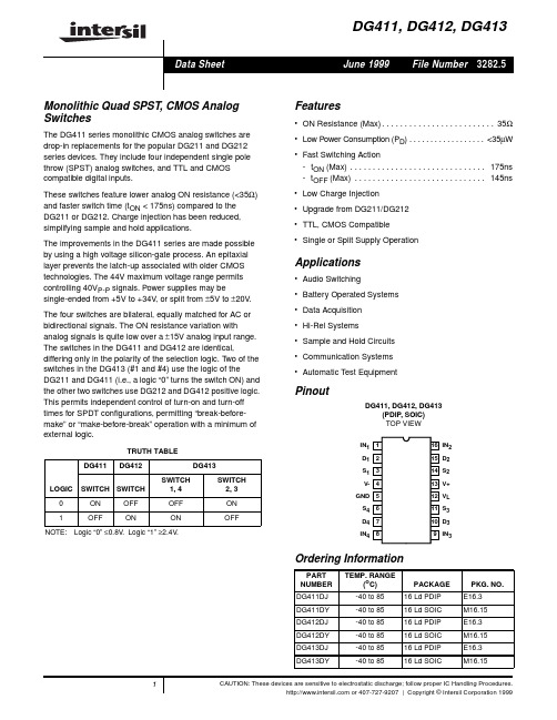
Pinout
DG411, DG412, DG413 (PDIP, SOIC) TOP VIEW
IN1 1 D1 2 S1 3 V- 4 GND 5 S4 6 D4 7 IN4 8
16 IN2 15 D2 14 S2 13 V+ 12 VL 11 S3 10 D3 9 IN3
Ordering Information
100
Maximum Junction Temperature (Plastic Packages) . . . . . . . .150oC
Maximum Storage Temperature Range . . . . . . . . . . -65oC to 150oC
Maximum Lead Temperature (Soldering 10s) . . . . . . . . . . . . 300oC
DG411
DG412
DG413
S1
S1
S1
IN1
IN1
IN1
D1
D1
D1
S2
S2
S2
IN2
IN2
IN2
D2
D2
D2
S3
S3
S3
IN3
IN3
IN3
D3
D3
D3
S4
S4
S4
IN4
IN4
IN4
D4
D4
D4
Schematic Diagram (1 Channel)
V+
VL
INX
GND V-
Pin Descriptions
Whichever Occurs First Continuous Current (Any Terminal) . . . . . . . . . . . . . . . . . . . . . 30mA Peak Current, S or D (Pulsed 1ms, 10% Duty Cycle Max) . . 100mA
风扰模拟力加载器控制系统设计

风扰模拟力加载器控制系统设计作者:任雅广王校锋姚跃亭来源:《计算技术与自动化》2013年第03期作者简介:任雅广(1969—),男,江苏沭阳人,高级工程师,硕士研究生,研究方向:船舶机电管理及控制;王校锋(1979—),男,浙江绍兴人,工程师,硕士研究生,研究方向:船舶机电管理及控制(E-mail:yyt_hehe169@)。
摘要:针对用于风扰模拟的力加载器系统,设计以DSP为核心的数字控制器。
在传统的位置伺服控制的基础上,设计力反馈控制回路,同时使用前馈补偿抑制由于承载对象运动而导致的多余力。
使用粒子群算法进行控制器参数整定。
试验结果表明,该力加载器能够进行有效地进行各种类型的风扰模拟,具有较高的控制精度和响应速度,能够良好的克服多余力干扰。
关键词:力加载;风扰模拟;PID控制;粒子群算法中图分类号:TP273 文献标识码:A1引言地面半实物仿真是控制系统研制过程中的重要步骤,是验证控制系统性能和关键环节。
力加载器是一种在实验室环境下模拟被控系统的负荷或扰动的物理效应设备。
在飞行器研制过程中,为了在地面上模拟飞行器实际飞行时的舵面铰链力矩,通常设计力矩模拟器[1-5]。
另外在风力发电、舰载设备等室外装置的研制中,为了模拟自然界的风扰动,也需要研制设计能够模拟自然界风扰的力加载系统[6,7]。
力矩加载器和力加载器都数据负载模拟器的范畴。
常见的负载模拟器有电液负载模拟器、电动负载模拟器、气动负载模拟器等类型。
其中电动负载模拟器具有体积小、成本低、结构简单等优点,而被广泛研究使用。
承载对象的运动对于力加载器而言,是一种严重的外部干扰,会产生的多余的控制力,因此多余力抑制问题一直是力加载器研制中的难点[8,9]。
本文针对一款电动力加载器进行了控制系统设计,包括控制系统的硬件组成,控制策略和控制律设计,以及多余力消除方法和控制参数优化等问题的研究。
2力加载器系统构成力加载器由电动作动装置和控制系统组成。
COPLEY驱动器用户指南

Copley驱动器总结
一、驱动器简介
-S和-R版本可以从模拟正弦/余弦编码器和无刷解析器中模拟出正交编码器的输出信号,我们的驱动器是XTL-230-40,输入标准版本,支持正交编码器。
驱动器可以以以下几种方式进行操作:
1. 作为一个传统的电机驱动器,接受外部控制器发出的电流,速度和位置信号。
在电流和速度模式下,可以接受正负10V的模拟信号;占空比50%的PWM波,或者PWM/极性输入。
在位置模式下,输入可以是从步进电机控制器发出的位置增量命令(以脉冲方向格式或者递增递减计数格式)或者是从主编码器输出的A/B正交指令。
2. 作为CANopen网络的一个网点。
3. 作为DeviceNET网络的一个网点。
4. 作为一个独立的控制器运行虚拟机上的程序,或者通过RS232串口运行ASCII码格式的
指令。
另外还需要一个独立的+24V电源给内部控制电路供电,这个电源跟主电源隔离开来。
这个设计保证了主电源断开,+24v电源不断开的时候,驱动器能保留位置信息和通信。
CME2
CME2是对驱动器进行配置和调试的软件,通过RS232串口连接电脑和驱动器。
所有的配置驱动器的操作都可以通过这个软件完成。
电机数据存储为.CCM文件,驱动器数据存储为.CCX文件。
1。
Copley+驱动调试帮助

Copley驱动调试帮助向导1.到/Motion/Products/Software/index.html 下载CME2软件并进行安装。
2.软件安装完成后,用RS232通讯线缆将驱动器与电脑串口相连,连接完成后给驱动器上电,再点击桌面“CME2”图标打开软件,如图1 所示:图1点击“OK”后,出现图2界面:图2(以XSL-230-18驱动为例)3.驱动器基本配置点击“Amplifier”菜单下“Basic Setup”或点击图标工具栏第一个图标,出现图3窗口:图3在图3中可以看到当前驱动器的配置情况,如要改变设置,请点击“Change Settings”,进入“Motor Options”设置,出现图4窗口:图4Motor Family(电机类别):Brushless:无刷电机Brush:有刷电机Three Phase Stepper:三相步进电机Motor Type(电机类型):Rotary:旋转电机Linear:线性电机再点击“Next”进入“Feedback Options”设置,出现图5窗口:图5Hall Type(Hall类型):None:没有HallDigital:数字HallAnalog:模拟Hall(Copley直线电机专用)当有Hall时,请勾上“Hall Phase Correction”。
Motor Encoder(电机编码器):None:没有Primary Incremental:主通道数字编码器接口Secondary Incremental:第二通道数字编码器接口Analog:模拟信号编码器接口Low Frequency Analog:低频模拟信号编码器接口(Copley直线电机专用)Position Encoder(位置编码器):None:没有Primary Incremental:主通道数字编码器接口Secondary Incremental:第二通道数字编码器接口Analog:模拟信号编码器接口Position Encoder Type(位置编码器类型):Rotary:旋转Linear:线性Use Position Encoder In Passive(Monitor)Mode:将位置编码器用于监控模式[注]:XSL,XSJ,ACP,ACJ四款驱动均有两个数字编码器通道,两个通道可任意配置为电机编码器或位置编码器。
ATMLH412
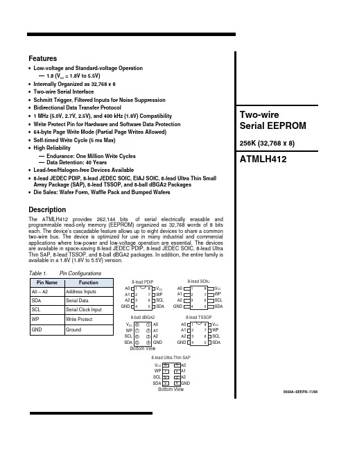
Table 1. Pin Configurations
Pin Name A0 – A2 SDA SCL
Function Address Inputs Serial Data Serial Clock Input
WP
Write Protect
GND
Ground
8-lead PDIP
A0 1 A1 2
8 VCC 7 WP
Absolute Maximum Ratings*
Operating Temperature...........................• 55°C to +125°C Storage Temperature ............................• 65°C to + 150°C Voltage on Any Pin with Respect to Ground................................ • 1.0 V +7.0V Maximum Operating Voltage.....................................6.25V DC Output Current ..................................................5.0 mA
CC
internally pulled down to GND. However, due to capacitive coupling that may appear during customer applications, Atmel recommends always connecting the WP pins to a known state. When using a pull-up resistor, Atmel recommends using 10kΩ or less.
- 1、下载文档前请自行甄别文档内容的完整性,平台不提供额外的编辑、内容补充、找答案等附加服务。
- 2、"仅部分预览"的文档,不可在线预览部分如存在完整性等问题,可反馈申请退款(可完整预览的文档不适用该条件!)。
- 3、如文档侵犯您的权益,请联系客服反馈,我们会尽快为您处理(人工客服工作时间:9:00-18:30)。
• No integrator windup
when disabled
• 3 LED’s for faster setup:
Normal/enable, power-OK, Fault (short or overtemp)
• Fault protections: • • • • •
Short-circuits from output to output, output to gnd Over/under voltage Over temperature Self-reset or latch-off modes 3kHz Bandwidth Wide load inductance range: 0.240 mH. Surface mount technology construction, lower part count.
FEATURES
• UL Recognized Component
• Flexibility! Internal 40-pin
socketconfigures amp with no soldering
• Separate current limits:
Continuous, peak, and peak-time
±30A @ ±170V ±15A @ ±170V Ro = 0.1
±20A @ ±215V ±10A @ ±215V Ro = 0.2
Selectable with components on header socket: 200 µH to 40mH Current mode: Voltage-feedback mode: 3kHz with 200µH load at maximum supply voltage, varies with load inductance and RH20, CH18 values 200Hz max. 25kHz Differential, 100K between inputs, ±20V maximum 1.0 : 1 (Volt / Volt) Ipeak / 6V ( I peak = peak rated output current; 6V measured at Current Ref J2-9 or Current Monitor J2-8 )
TECHNICAL SPECIFICATIONS
MODEL OUTPUT POWER Peak power Peak time Continuous power OUTPUT VOLTAGE Ro = 0.2 LOAD INDUCTANCE BANDWIDTH (Small signal, -3dB. freq) PWM SWITCHING FREQUENCY REFERENCE INPUT GAINS Input differential amplifier PWM transconductance stage LOGIC INPUTS ±20A @ ±80V ±10A @ ±80V 412
FEATURES
The 400 series are third-generation amplifiers for dc brush motors from Copley Controls Corp. Models operate from +24 to +225VDC unregulated power supplies, and output peak currents from 10 to 30A. Built using surface-mount technology, these amplifiers offer a full complement of features for servo motor control. All models take industry standard ±10V control signals as input, and operate motors in three different modes: torque, velocity, and voltage feedback with IR compensation. Torque-mode finds the widest application for motors used with digital control cards that take encoder feedback from the motor for velocity and position control. Velocity loops using brush-tachometer feedback are used for open-loop speed controls, or in position control loops requiring superior regulation at low speeds. Tachless speed controls can be made using output voltage feedback with IR compensation where lowest cost is required. Active logic-level of /Enable, /Pos Enable, and /Neg Enable inputs is switch-selectable to interface with all types of control cards. Ground-to-enable or ground-to-inhibit are both supported. Mosfet H-bridge output stage delivers power in four-quadrants for bi-directional acceleration and deceleration of motors. An internal 40-pin header socket holds components that configure the various gain and current limit settings to customize the amplifiers for a wide range of loads and applications. Individual peak and continuous current limits allow high acceleration without sacrificing protection against continuous overloads. Peak current time limit is settable to match amplifier to motor thermal or commutation limits. Header components permit compensation over a wide range of load inductances to maximize bandwidth with different motors. All models are protected against output short circuits ( output to output and output to ground ) and heatplate overtemperature. With the /Reset input open, output shorts or heatplate overtemperature will latch off the amplifier until power is cycled off & on, or until the /Reset input is grounded. For self-reset from such conditions, wire /Reset to ground and the amplifier will reset every 50ms. Three status LED’s speed diagnostics during set-up, or for fault isolation after the unit is in service.
Input voltage range Logic threshold voltage ( LO to HI transition ) /Enable ( S1 OFF; S1 ON reverses logic ) /POS enable, /NEG enable ( S1 OFF; S1 ON reverses logic ) /Reset Input resistance DIP SWITCHES S1: Enab LO/HI Default: OFF S2: Integrator ON/OFF Default: ON POTS Ref Gain Tach Gain Loop Gain Integ Freq Balance/Test LOGIC OUTPUTS +Fault ( /Normal ) HI output voltage LO output voltage INDICATORS (LED’s) Normal Power OK Fault MONITOR OUTPUTS Current Monitor ( motor or load current ) Current Ref ( current demand signal to PWM stage ) Voltage Monitor ( load voltage at output terminals ) DC POWER OUTPUTS PROTECTIVE FEATURES Output short circuit (output to output, output to ground) Overtemperature Undervoltage shutdown @ <22V