沃尔玛门店LS4278安装使用说明
沃尔玛Fault Finder和Fault Finder Remote操作手册与保修说明书

Operator’s ManualFault Finder and Fault Finder / Remote WaRRanty InstRuctIOns LIMITED WARRANTY - A Fault Finder orFault Finder / Remote Warranty is provided to the original purchaser for a period of one (1) year from the date of purchase, when used in accordance with the operating instructions. Y ou must retain your receiptfor proof of purchase. This warranty covers defects in materials and workmanship to the Fault Finder or Fault Finder / Remote. TERMS THAT APPLY TO THE WARRANTY Improper installation, misuse, neglect and tampering of any kind are NOT covered under the Limited Warranty. Fault Finderor Fault Finder / Remote, returned under the Warranty will be inspected and if the problem is determined to be the result of neglect or abuse, then no warranty will be applied. No warranty other than the above is expressed or implied. Implied warranties of merchantability and fitness for a particular application are hereby disclaimed unless the law specifically precludes this disclaimer. The manufacturer and seller have no liability for damages, incidental or consequential, resulting from or caused by any failure, malfunction or defect of any product.TO MAKE A WARRANTY CLAIM -1. Fault Finder or Fault Finder / Remote, returned for warranty work must be accompanied by a copy of the original sales receipt/invoice and a note showing the customer name, phone number, return address (where the unit will be returned to) and a brief description of the problem.2. Pack product carefully in oversized carton with crushed newspaper (or other appropriate packing materials) for cushioning.3. The product should be shipped PREPAID and insured against shipping loss or damage.4. Send warranties to:Power Wizard10375 ST RT 43 Streetsboro, OH 44241 1-800-866-2161IntROductIOnDepending on the model purchased, there are 3 major functions that the Fault Finder or Fault Finder / Remote can perform.1. VOLTMETER - Displays theelectric fence voltage in kilovolts ( kV ). 1kV = 1000 volts. Benefit: Measuring fence voltage helps determine the effectiveness of the electric fence system.2. CuRRENT METER - Displays the current in (amps) that is flowing through the fence wire. Benefit: Measuring the current through the hot fence wire will help locate faults (shorts) inthe fence system. Fence shorts reduce fence energizer [shock] effectiveness.3. R EMOTE CONTROL - Allows the user to turn the Energizer on-or-off from any location on the fence. (This unique function is only available in the Fault Finder with “Remote” andonly works with remote-ready electric fence Energizers). Benefit: Conveniently save time by turning the energizeron-or-off from any location on the fence (through the hot wire).*Fault FIndeR specIFIcatIOns • Voltage range - .3 to 18 kV• Current range - 2 to 150 amps • Battery - 9 Volt Alkaline*Specifications are subject to changepaRts and theIR FunctIOn IMaGe 1IMPORTANT: The Fault Finder or Fault Finder / Remote does not have a lighted display and was not designed to work in low light conditions. It is not recommend to install or repair electric fencing in low light conditions.pOWeRInG the Fault FIndeR On-OR-OFFON - Press and release the Fault Finder ( ) power button.VoltagecurrentFault direction arrow Fence pulse low Battery power Button and kV / a toggle energizer Off Button (With RemoteVersion Only)energizer On Button (With Remote Version Only)Battery cover and Ground plate Belt clipFence hook Fault direction arrowOFF - When turned on, the Fault Finder will automatically turn off in 1 minute if not in use. To turn the Fault Finder off manually, press and hold the ( ) power button for a few seconds.MeasuRInG Fence VOltaGe1. T urn the Fault Finder on.2. Press the ( ) power button to toggle between the volt and amp function until the kV symbol is displayed on the right hand side of the display(See image 1).3. Firmly hold the Fault Finder with your bare hand (do not wear gloves). Pressing your thumb firmly on top of the Fault Finder, position your fingers to make contact with the metal ground plate (battery cover) on the back. Since the Fault Finder does not require any additional wires for grounding, the Fault Finder relies on your body for the ground. Therefore, making good contact with the metal ground plate is important (See image 2).4. Place the Fault Finder’s fence hook onto the fence wire(See image 3).Each time the energizer pulses, a “lightning bolt” will appear at the top of the display to indicate a fence pulse has been measured. The fence voltage will then be displayed, in kilovolts (kV), at the center of the display. NoTE: If the “lightning bolt” is flashing and voltage readingis “Lo”, then the voltage being measured by the Fault Finder is below the range of measurement.If the “lightning bolt” is flashing and voltage reading is “HI”, then the voltage being measuredby the Fault Finder is above its range of measurement.IMaGe 2MeasuRInG Fence cuRRent1. T urn on the Fault Finder.2. Press the Fault Finder ( ) power button to toggle between the volt and amp function until the “A” symbol is displayed on the right hand side of the display.3. Firmly hold the Fault Finder with your bare hand (do not wear gloves). Pressing your thumb firmly on top of the Fault Finder,position your fingers to make contact with the metal ground plate (battery cover) on the back. Since the Fault Finder does not require any additional wires for grounding, the Fault Finder relies on your body for the ground.Therefore, making good contact with the metal ground plate is important (See image 2).Place the Fault Finder’s fence hook onto the fence wire(See image 3).Each time the energizer pulses, a “lightning bolt” will appear on the top of the display to indicate a fence pulse has been measured. The fence current will be displayed, in amps (A), at the center of the display. Above the current reading an arrow pointing to either theleft or the right will also be displayed. These arrows indicate the direction of the current flow and will help to locate the faults (shorts) in the fence.NOTE: If the “lightning bolt” is flashing and current readingis “Lo”, then the current being measured by the Fault Finder is below the range of measurement. If the “lightning bolt” is flashing and current reading is “HI”, then the current being measuredby the Fault Finder is above its range of measurement.The current reading should not be taken if the fault finder is in close proximity to the energizer as it will give inaccurate readings.tuRnInG the eneRGIzeROn-OR-OFF(Fault FIndeR / ReMOte Only) Please check with the manufacturer as to which Energizer is compatible with the Fault Finder / Remote.1. Turn on the Fault Finder / Remote.2. Firmly hold the Fault Finder with your bare hand (do not wear gloves). Pressing your thumb firmly on top of the Fault Finder, position your fingers to make contact with the metal ground plate (battery cover) on the back. Since the Fault Finder does not require any additional wires for grounding, the Fault Finder relies on your body for the ground. Therefore, making good contact with the metal ground plate is important (See image 2).3. Place the Fault Finder’s fence hook onto the fence wire (See image 3).Fence hook to fence wire contact is needed to transmit the on/off signals.OFF – press and release the ( ) OFF button and the display will show “OFF” indicating that a signal was sent to the Energizer. After the signal is sent, the Fault Finder / Remote will return to measuring current or voltage.ON – press and release the ( ) ON button and the display will show “ON” indicating that a signal was sent to the Energizer. After the signal is sent, the Fault Finder / Remote will return to measuring current or voltage.IMpORtant tIps When usInG the ReMOte FeatuRe:Before removing the Remotefrom the fence, always check the voltage on the fence to ensurethe Energizer received the on-or-off signal. The easiest way to determine if the Energizer is on,is to check the display for the “lightning bolt” indicator.If the Energizer did not turn on-or-off, ensure that the wire being used to send the signal is not open and is connected to the Energizer’s hot wire. If the hot fence wire being used is rusted or corroded and the Remote will not work, move to a different fence location where the fence wire is not rusted or corroded.A low battery will reduce the Remote’s ability to effectively transit the on-off signal to the energizer. Replace the battery if the battery indicator is shown on the display. IMaGe 3selectInG and chanGInG the channel On the Fault FIndeR / ReMOte and eneRGIzeR (Fault FIndeR / ReMOte Only) By default from the factory the Fault Finder / Remote and the Energizer are both set to channel 1.It is not necessary to change to a different channel if you do not have multiple Energizers with remote ca-pability next to or on adjacent fences. To select and change the channel on the Remote and the Energizer:1. Turn on the Fault Finder / Remote.2. Hold the Remote next to the Energizer and press the ( ) OFF button to put the Energizer into standby mode. See the Ener-gizer’s operator manual for details as Energizer models may vary.3. Press and hold down the ( ) power button then press the ( ) OFF button. The current channel set in the Remote will be displayed. Example “ch1”.4. Press and release the ( ) OFF button to toggle through the available channels on the Remote.5. Once the desired channel is displayed on the Remote hold the Remote next to the Energizer and press the ( ) ON button.The Energizer will now confirm that the new channel has been accepted. “See the Energizer’s operator manual for details as Energizer models may vary”. note: If changing the channel on the Remote is needed to match the channel on the energizer, perform steps 3 through 5 without holding the Remote next to the energizer. What tO KnOW BeFORe lOOKInG FOR a Fault On yOuR FenceIt is important to know, when using the Fault Finder for the first time, that a large current reading on the fence does not necessarily mean that there is a critical fault on your fence. The larger the Energizer and the fence that is connected, as well as vegetation on the fence, are all factors that will increase the current reading.It is recommended to first go around the perimeter of the fence and take voltage readings at various locations to determine the effectiveness of your fence system. If, at various fence locations, you have around 3000 volts or moreit is probably not necessary to troubleshoot your fence.If locations on your fence measure less than 3000 volts (depending on the size of the Energizer),then it is recommended that you troubleshoot your fence. Check the Energizer and grounding systemto ensure they are adequate for your electric fence size. If eitherthe Energizer or the groundingsystem is insufficient, for yourfence size, then correct this beforetroubleshooting your fence. (Checkyour fence Energizer manualfor details on the Energizer andchecking the grounding system).Y ou should check your ground sys-tem 2 times a year, even if the fenceseems fine. The ground system isone of the most important aspectsof your electric fence system. Itcompletes the circuit between thehot fence wire, animal contact, andthe Energizer ground terminal. undeRstandInG the Fence cuRRent and VOltaGe ReadInGs To understand how the Fault Finderwill help you find a fault on thefence, it is helpful to understand theconcept of what you are measuring,as it relates to the effectiveness ofyour electric fence system.Let’s use a water hose analogyto understand your electric fence.Think of the Energizer as a waterpump and the electric fence wireas a water hose.The Fault Finder (amp) readingcan be thought of as showingthe amount of water leaks in thehose, with small holes (leaks), atvarious locations along the hose.All fences, even under normalcondition, will have small leaks(fence hot to fence ground leaks).Expect a larger fence to showlarger current readings since it willnaturally have more leaks (faults).Using a larger Energizer will have more flow and this causes the fence to have bigger leaks (faults). More flow will result in a larger current (amp) reading. Vegetation on the fence is alsoa leak and this will also cause a larger current reading. Common leak locations will be grass/weeds in contact with a hot fence wire, tree limbs that are in contact with a hot wire, old cracked insulators, or any other object that comes in contact with both the ground and the hot fence wire.When you are measuring the current at the beginning of the fence you are measuring all the leaks (faults) in the fence. The farther you go from the Energizer the less the current is on the fence. This is because you are measuring less of the fence total leaks (faults) the farther you walk away.The voltage reading on the Fault Finder can be thought of as the amount of water in the hose. This is why the more leaks (faults) there are, the lower voltage reading. This is the reason why fence voltage can be less as you go farther from the Energizer. The less the voltage is on the fence is a result of all the small leaks. (There is less and less water in the hose.)hOW dO yOu use the ReadInG tO FInd a Fault On the Fence?2 types OF Fence cOnFIGuRatIOnsTYPE 1: Fence does not loop back to the Energizer - When using the Fault Finder in a non-looping fence (See example A or B), the current arrow direction is not needed to determine the location of the fault, and can be ignored.TYPE 2: Fence loops back to the Energizer - When using the Fault Finder with a fence that loops back to the Energizer (See example C), the current arrows are used to determine the location of the fault.In normal conditions, as youtest along a fence with no loopsor faults, the fence current will decrease the farther you are from the Energizer (See example A).If you have a fence with oneor more major faults, as youtest along the fence there will beexcess amounts of current on the fence. As you pass the point of the fault, the current will rapidly drop. At this point simply go backwards on the fence and find the exact point, where, on each side, thereis the large change in current. Thisis where your fault is located (See example B).With a fence with loops and faults, as you test along the fencethe current will point in the direction of the current and as you passthe point of the fault the current direction will change. At this point simply go backwards on the fence and find the exact point, where, on each side, there is a change in the direction of the current. This is where your fault is located.ReplacInG the BatteRyWhen the ( ) low batterysymbol appears on the display it is time to replace the 9 volt battery. For longer battery life it is recommend using a 9 volt alkaline type battery.1. Remove the battery cover by unscrewing the 2 screws on the bottom/back metal piece of the Fault Finder. It’s recommended you do this over a table so you do not lose the 2 small battery cover screws.eXaMple a - nOn-lOOpInG Fence WIthOut FeXaMple B - Fence WIth One OR MORe Maj- 14 -eneRGIzeR6.0aMps 3.0aMps eneRGIzeR20.0aMps 18.0aMpsFault(Short toGround)eXaMple a - nOn-lOOp thROuGh BOth WIRes eXaMple c - Fence lOO 2. Remove the old battery and replace it with the new battery. When replacing the new battery check the polarity as shown in the battery compartment to ensure the battery is connected correctly. If you must force the battery then the polarity is most likely reversed.3. Put the battery cover back inplace and carefully screw in the 2 screws. tighten the screws but don’t apply excessive force to prevent stripping the screw. caRInG FOR the Fault FIndeR / ReMOte• Do not leave the Fault Finderin direct sunlight, for instance on the dash of a vehicle. TheFaultsjOR Faults- 15 -2.0aMps 1.0aMps eneRGIzeR10.0aMps3.0aMps 1.0aMps eneRGIzeReneRGIzeRpInG Fence WIth cuRRent shaRed Ops BacK tO eneRGIzeRextreme heat may damage theFault Finder.• Use only a lightly damp cloth to clean the Fault Finder.• Y our Fault Finder is waterresistant not water proof. Donot submerge the Fault Finderin water.• Remove the battery if the Fault Finder is not being used for anextended period of time. Thiswill prevent damage to the FaultFinder from battery leakage.- 16 -5.0aMps5.0aMps1.0aMps1.0aMpsFaultIndicatescurrentdirection。
威尔各系列终端机的门禁安装与软件设置

各系列终端机的门禁安装与软件设置各系列终端机的门禁安装与软件设置 (1)一、各系列门锁接线图: (1)S系列接线图: (1)V系列接线图: (2)S、V型设备测试说明 (3)F(5v)系列与门控器接线图: (4)F系列设备测试说明 (7)FB(12v)系列门禁接线图 (8)FB(12V)型设备测试说明 (9)H系列门禁接线图 (10)H(12V)型设备测试说明 (12)二、各管理软件中的门禁设置 (13)B/S软件门禁设置: (13)C/S软件门禁设置: (15)一、各系列门锁接线图:S系列接线图:外观图:(S6)断电开门型电锁如下图:通电开门型电锁如下图:V系列接线图:外观图:(V8)断电开门型电锁接线图:通电开门型接线图如下:如上图所示,两种型号设备可以接断电开门型或者通电开门型电锁,或者输出继电器开关信号,用来接其他设备例如:其他门禁设备、三滚闸、翼闸、自动门等。
当接其他设备时比如门禁电源,我们只接出C和NO点,用来输出开关信号,接在门禁的开门按钮上即可。
如果电控锁的工作电压为DC12V且持续工作电流≤500mA,启动电流≤800mA则可以使用本机供电。
如果电控锁不符合上述要求则必须使用外供电模式,具体使用电源请参照电控锁使用说明。
注意:不按接线图纸连接或使用错误的外供电电源都有可能造成机器或电控锁的失效或永久性的损坏,而且这种损坏是不在保修范围之内的,并且制造商也不会承担由此造成的额外损失。
S、V型设备测试说明首先做测试:1.当电锁和开门按钮连线都接好时,接通终端机电源,这时锁会闭合,按开门按钮看看锁是否打开,不好用需检查连线是否正确。
2.开门按钮可以开门后,在考勤机上登陆设备管理界面,则在考勤主界面按【MENU】键弹出对话框录入超级管理员编号(出厂编号为0000),录入管理员编号后按【ENT】键进入设备管理操作菜单。
如下图:选择【档案管理】,在本机新增一个临时员工编号(临时人员仅仅在演示或者测试时使用,不能做正式档案用,当管理端软件把数据采集后,临时人员的信息会丢失,新增临时人员演示密码为‘6719’),如图所示选择【新增编号】,输入编号‘1’,然后为新增人员发卡或者录入一枚指纹(这要看考勤机类型),按照提示录入完毕后,退出管理菜单进入识别界面。
收银台系统总安装说明

双工位收银台 单工位收银台
三工位收银台
2011版收银台货架系统--安装说明书
步骤三.挂上灯箱
6*10内六角盘头螺钉 连接槽管(左右)与横杆
步骤二.用角码+M6*10内六角盘头螺钉 将背板,底板固定在槽管上
侧板一侧靠墙时,应在步骤四之前先挂靠墙面侧板 相邻两灯箱间用螺钉螺母对撬 保证灯箱齐平 挂上侧板后,用螺钉由内向外锁紧 步骤四.按前步骤的方法将货架装成一组 接上电源,灯箱用快速接头串联 只能串联5个以下,超过的部分必须从电源另接一路
1345
玻璃层板
烟层板使用方法: 烟放入亚克力盒内,圆柱放在烟后 拿出一包烟后,利用圆柱重力,推进香烟
烟层板 横杆 侧板(左右) 槽管(左右) 角码 底板
步骤五. 侧板上拧入三个螺钉 再将侧板挂入槽管的葫芦孔上
2
步骤六.挂上玻璃层板,香烟层板 安装完成
2011版收银台货架系统--安装说明书
500
0 R5
换画面方法: 用吸盘吸注亚克力,向上提,向外拉 喷绘画面,尺寸:405*598,材质:灯光片
1782 1452.8
152 °
598
350 此面与收银台背柜齐平 灯箱 背板
MagIQ Link模块安装指南说明书

OR
2. HEATER
OR
3. AIR SENSOR
1. WALL CONTROL
(MAGIQ TOUCH CONTROLLER)
Cable lengths between all other components should be no greater than 20m. For more information, refer to System Configuration diagrams at the end of this manual.
SAFETY
EMPLOYER AND EMPLOYEE RESPONSIBILITIES
The installation and maintenance of evaporative coolers at height has the potential to create Occupational Health and Safety issues for those involved. Installers are advised to ensure they are familiar with Local Acts, Regulations and Standards, which may offer practical guidance on health and safety issues. Compliance with these regulations will require appropriate work practices, equipment, training and qualifications of workers. INSTALLER AND MAINTENANCE CONTRACTORS– RISK ASSESSMENT
收款机软件安装与使用说明
收款机软件安装与使用说明
1、系统安装
点击随机附带光盘里的SKSystem1.1.exe 运行程序到下图
点击【下一步>】按钮,进入
填写公司及名称点击【下一步>】按钮,进入
选择安装路径,上图是默认安装路径,建议安装在非系统盘,点击【下一步>】,进入
选择“完整安装”,点击【下一步>】,进入
点击“安装”,开始安装
以上正在安装中
点击【完成】,退出安装步骤。
安装成功。
2、初次使用指南
第一步:双击桌面“SKSystem1.1”的图标,:初始密码为123
系统界面如下
系统管理员新增—修改—删除
新增界面填写用户名—描述—密码—确认密码—确定
机器通讯设置,机器默认数据编号001,通讯波特率9600
3.发送和接收编程综合数据
功能参数编程
要修改直接双击修改
收据题头编程
营业员编程
外汇编程
套餐编程
开台编程
部类编程
商品PLU编程
直接PLU编程
4.接收入账综合报表
财务报表
小时报表
当日报表
当日月报表
收款员报表
营业员报表
签单客户报表
退货报表
部类报表
开台销售报表
5.入账报表数据财务报表统计
部类报表统计
收款员报表统计
小时报表统计
退货报表统计
营业员报表统计。
摩托罗拉条码平台通用设置
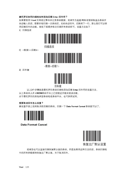
摩托罗拉条码扫描枪如何添加后缀Enter回车符?如果要使用Word文档或记事本来记录条码数据,或者作为商超POS收银读取商品条码并自动输入的话,想要在每扫描一次条码后,光标自动回车,切换到下一行,那么我们可以使用后缀回车的功能,按找下面顺序依次扫描所有条码即可。
设置方法如下:1)扫描选项2)<数据><后缀1>3)回车键以上3个步骤就是摩托罗拉条码扫描枪添加后缀Enter回车符的设置方法。
以上条码本人在LS9208条码平台上已经验证并能实现该功能。
对于摩托罗拉的其他类型条码枪或条码平台,也可参照试用。
想要取消回车怎么设置?在设置手册上找到取消前后缀的条码,扫描一下Data Format Cancel条码就可以了。
或者您也可以直接扫描恢复默认值的条码,但是如果用这种方法的话,条码扫描枪中的所有参数都将恢复出厂默认值,关于取消回车,摩托罗拉条码扫描枪怎么添加TAB?只需在扫描枪手册上找到设置条码依次扫描即可。
摩托罗拉条码扫描枪添加TAB的前三步骤其实就是后缀回车的设置。
设置方法如下:1)扫描一次【扫描选项】条码2)扫描一次【<数据><后缀1>】条码3)扫描一次【回车键】条码4)扫描一次【扫描后缀】条码5)扫描一次【7】条码6)扫描两次【0】条码7)扫描一次【9】条码以上7步就是摩托罗拉LI4278条码扫描枪添加TAB的设置方法,如果您没有设置手册,可以在扫描网LI4278产品介绍页面,或者在导航中的手册下载页面,下载LI4278快速入门指南中文版。
里面就有详细的设置介绍。
关于摩托罗拉条码扫描枪的八种数据传输格式,扫描枪用户可根据自己的工作需要相应选择;可以根据此文中条码扫描枪的扫描数据传输格式,选择以下您需要的数据格式来对扫描枪进行设置。
或者,您也可以参考条码扫描枪的设置手册。
MOTO条码扫描枪的扫描数据传输格式图:以上MOTO条码扫描枪的“数据传输格式”条码对应中文如下:1)Data As Is →数据是2)<DATA> <SUFFIX 1> →<数据> <后缀1>3)<DATA> <SUFFIX 2> →<数据> <后缀2>4)<DATA> <SUFFIX 1> <SUFFIX 2> →<数据> <后缀1> <后缀2>5)<PREFIX> <DATA > →<前缀1><数据>6)<PREFIX> <DATA> <SUFFIX 1> →<前缀1><数据><后缀1>7)<PREFIX> <DATA> <SUFFIX 2> →<前缀1><数据><后缀2>8)<PREFIX> <DATA> <SUFFIX 1> <SUFFIX 2> →<前缀1><数据><后缀1> <后缀2>MOTO条码扫描枪有两种默认值:出厂默认值和自定义默认值。
收银机操作流程
POS收银机的操作规程(一)打开收银机1.打开收银机(1)打开收银机的步骤1)开启电源。
检查开关接触等情况,确认无误后开启电源开关,并检查其工作指示音是否正常。
不间断电源(UPS)用于在市电故障时继续提供电源,以保护设备及数据不受毁损,市电故障时,UPS将持续鸣叫以示警告。
2)开启显示器和微型票据打印机等外设的开关。
待UPS工作指示音正常后,开启收银员显示器和微型票据打印机等外设的开关,顾客显示屏、POS键盘和钱箱没有电源开关,由主机直接供电。
3)开启POS收银机主机的电源开关。
此时可听到条形码扫描器通电指示音,同时系统将自动执行管理软件,直至进入相应的待机界面。
(2)处理打开收银机时的故障1)处理网络故障。
对于使用联网设备的收银机,如果系统在执行完检测网络后提示“网络故障”,应按如下顺序检查:第一步,检查确认后台管理系统所在的PC机是否已经开启,并已顺利进入后台管理。
第二步,检测网络接头是否连接在POS收银机主机背面的LAN口上,并确认是否接触良好。
第三步,如果有使用交换机或集线器进行网络连接,请确认交换机或集线器是否已通电,并确认其背面所有的接头是否均已接上并接触良好。
第四步,检测后台PC机背面的LAN口上是否接有网络接头,并且接触良好。
2)处理打印机错误。
如果系统检测时出现打印机错误,应按如下步骤处理:第一步,确认打印机电源线连接良好,且电源开关已开启。
第二步,确认打印数据线已连接到主机背后接口,且两端均接触良好。
第三步,检查微型票据打印机的收银纸是否已装好,如果是点阵式微型票据打印机要检查色带是否需要更换,且打印机盖关闭良好。
2.登陆销售系统(1)收银员登陆1)打开收银机后,首先选择进入POS销售系统。
2)在“员工登陆”窗口中,输入正确的员工编号,按Enter键。
3)之手输入登陆密码,然后按Enter键,如果密码正确即可进入系统。
4)系统进入销售操作界面。
(2)处理登陆失败1)如果收银员在输入员工编号及密码时出现错误,系统会要求重新输入,此时应仔细核对编号与密码,并重新输入。
LS4278LS4278快速参考指南

LS4278LS4278快速参考指南1.扫描模式设置-连接扫描器与电脑/设备。
通过USB或蓝牙连接扫描器和电脑/设备。
-打开设置扫描模式的软件。
-选择所需的扫描模式。
可以选择手动扫描、连续扫描、自动扫描等不同的扫描模式。
-保存设置并关闭软件。
2.扫描条形码-将条形码放置在扫描区域内。
-确保扫描区域与条形码保持一定距离,以确保扫描的准确性。
-按下扫描按钮或使用触摸屏上的扫描选项。
-扫描器将发出“滴”声,表示扫描成功。
3.数据传输设置-连接扫描器与电脑/设备。
-打开设置数据传输的软件。
-选择数据传输模式。
可以选择批处理模式、实时模式等不同的数据传输模式。
-保存设置并关闭软件。
-连接扫描器与电脑/设备。
5.蓝牙连接设置-打开扫描器的设置菜单。
-进入蓝牙设置。
-打开蓝牙扫描功能。
-手机或电脑上的蓝牙设置中扫描器并进行配对。
-配对成功后,可使用蓝牙进行数据传输。
6.扫描器维护-定期清洁扫描器的扫描窗口和镜头。
使用干净的布或纸巾擦拭。
-根据需要更换扫描器的电池。
确保使用适当的电池型号和规格。
-定期进行软件更新以保持扫描器的最新功能和性能。
7.故障排除-如果扫描器无法正常工作,请检查电池电量是否充足。
如果电量较低,请更换电池。
-检查扫描器与电脑/设备之间的连接是否完好。
重新连接或更换连接线。
-如果扫描器无法识别条形码,请确保条形码清晰可见,并尝试调整扫描器与条形码的距离。
总结:。
- 1、下载文档前请自行甄别文档内容的完整性,平台不提供额外的编辑、内容补充、找答案等附加服务。
- 2、"仅部分预览"的文档,不可在线预览部分如存在完整性等问题,可反馈申请退款(可完整预览的文档不适用该条件!)。
- 3、如文档侵犯您的权益,请联系客服反馈,我们会尽快为您处理(人工客服工作时间:9:00-18:30)。
2.将LS4278原装配的接口电缆一端插入到通讯座的主机端口中(见通讯 座部件说明)。
5B 3.将LS4278原装配的接口电缆的另一端连接到“Y线”端口 。端口 5A连接POS机键盘,如果是一体化的键盘则无需连接。
连接扫描枪 LS4278
连接 POS 机键盘 3. 如果适用,将接口电缆穿过电缆支座挂钩,并将主机电缆置于电缆 槽中。
瞄准
扫描 请确保扫描线完整穿过条码
对通讯座中的扫描器电池充电 要对扫描器电池充电,请将扫描器插入到通讯座中。当扫描器的 LED 指 示器开始呈绿色闪烁时,表明电池开始充电。使用外部电源充电为完全 放电的电池充满电最多需要三小时,使用非外部电缆电源则需要多达五 小时时间。
设置扫描枪
在正常情况下: 确认 LS4278 激光无绳扫描枪已正确安装完毕,只需要扫描配对条码, 连接扫描枪和底座:(在更换底座时也仅需扫描配对条码)
扫.描.L.S.4.2.7.8.通.讯.底.座.(.正.面.).的.配.对.条.码.!.!.
(说明:一定要扫描此条码,否则无线枪将无法使用)
当出现通讯问题时: 确认 LS4278 激光无绳扫描枪已正确安装完毕,设置如下:按顺序自上 而下逐一顺序扫描。
通讯座LED 指示器充电指示
通电时,通讯座的 LED 指示器始终呈绿色亮起。 将扫描器插入通讯座中充电
按下图所示放置扫描枪,先放置前边,再压下手柄。
维护
唯一需要的维护是清洁扫描窗口,脏了的扫描窗口会影响扫描的精确性 勿用硬物或尖锐物触碰窗口,以免磨花。 可以使用湿的软绵布清洁表面灰尘 使用 75%医用酒精和棉花球清洁窗口 不要直接喷射水或其他清洁液到扫描窗口
扫.描.L.S.4.2.7.8.通.讯.底.座.(.正.面.).的.配.对.条.码.!.!.
(说明:一定要扫描此条码,否则无线枪将无法使用)
LS4278使用说明
简介
LS4278 扫描器具备出色的扫描性能和高级的人体工程学设计两大优 势,充分挖掘了轻便型激光扫描器的价值。无论是手持模式还是采用支 架的免持模式,此款扫描器都能保证做到使用简便舒适ቤተ መጻሕፍቲ ባይዱ使用时间延长。
部件
插入/卸下电池
通讯座部件
LS4278通讯座和POS机连接
重要事项:请按照以下顺序连接接口电缆,以确保扫描器和通讯座正常 运行: