Time machine 21 马双
基于改进RRT_算法的六自由度机械臂路径规划

文章编号:1671-7872(2024)02-0173-09基于改进RRT 算法的六自由度机械臂路径规划朱永浩 ,李 丹 ,龚 旭 ,金仁才(安徽工业大学 电气与信息工程学院, 安徽 马鞍山 243032)摘要:针对快速扩展随机树(RRT)算法路径代价大、采样过程慢的问题,提出1种改进的RRT 算法对六自由度机械臂进行路径规划。
结合RRT*和RRT-connect 算法的优点,应用目标采样的思想加强算法向目标点搜索的趋向性,引入贪婪思想提高算法效率,结合五次B 样条插值对路径进行平滑优化,缩短规划路径的时间及长度;利用Python 中的matplotlib 功能包统计RRT 与改进的RRT 算法规划所需时长、采样点数与路径长度,且在ROS 平台中利用动态规划库进行算法配置,验证改进算法的路径规划效果。
结果表明:相比传统RRT 算法,采用所提改进算法对六自由度机械臂进行路径规划,在平均路径长度上缩短了29.5%、在规划路径时间上缩短了8.5%,路径规划成功率提高至96.7%,验证了该算法在实际应用中的可行性。
关键词:六自由度机械臂;路径规划;RRT ;目标采样中图分类号:TP 241.3 文献标志码:A doi :10.12415/j.issn.1671−7872.23113Path Planning of 6-DOF Manipulator Based on Improved RRT AlgorithmZHU Yonghao, LI Dan, GONG Xu, JIN Rencai(School of Electrical & Information Engineering, Anhui University of Technology, Maanshan 243032, China)Abstract :An improved rapidly-expanding random tree (RRT) algorithm was proposed to plan the path of a six degree of freedom (DOF) robotic arm in response to the problem of high path cost and slow sampling process in the RRT algorithm. Combining the advantages of RRT * and RRT-connect algorithms, the target sampling was applied to enhance the tendency of the algorithm to search for target points, the greedy thinking was introduced to improve the efficiency of the algorithm, and the quintic B-spline interpolation was combined to optimize the path smoothness,shorten the path planning time and length. The matplotlib function pack in Python was used to calculate the time,number of sampling points, and path length required for RRT and improved algorithm planning, as well as the dynamic planning library for algorithm configuration on the ROS platform was used to verify the path planning effect of the improved algorithm. The results show that compared with the traditional RRT algorithm, the path planning of the six DOF robotic arm by the proposed improved algorithm shortens the average path length by 29.5%,the planning path time is shortened by 8.5%, and the success rate of path planning is increased to 96.7%,which verifies the feasibility of the algorithm in practice.Keywords :six degree of freedom robotic arm; path planning; RRT; target sampling随着机器人技术的发展,机械臂具有工作空间大、操作简便、灵活性和自由度高等优点[1],在焊缝焊接、制造加工、拆卸装配、喷漆和码垛等领域得到越来越广泛的应用[2−4]。
Native Instruments MASCHINE MK3 用户手册说明书

The information in this document is subject to change without notice and does not represent a commitment on the part of Native Instruments GmbH. The software described by this docu-ment is subject to a License Agreement and may not be copied to other media. No part of this publication may be copied, reproduced or otherwise transmitted or recorded, for any purpose, without prior written permission by Native Instruments GmbH, hereinafter referred to as Native Instruments.“Native Instruments”, “NI” and associated logos are (registered) trademarks of Native Instru-ments GmbH.ASIO, VST, HALion and Cubase are registered trademarks of Steinberg Media Technologies GmbH.All other product and company names are trademarks™ or registered® trademarks of their re-spective holders. Use of them does not imply any affiliation with or endorsement by them.Document authored by: David Gover and Nico Sidi.Software version: 2.8 (02/2019)Hardware version: MASCHINE MK3Special thanks to the Beta Test Team, who were invaluable not just in tracking down bugs, but in making this a better product.NATIVE INSTRUMENTS GmbH Schlesische Str. 29-30D-10997 Berlin Germanywww.native-instruments.de NATIVE INSTRUMENTS North America, Inc. 6725 Sunset Boulevard5th FloorLos Angeles, CA 90028USANATIVE INSTRUMENTS K.K.YO Building 3FJingumae 6-7-15, Shibuya-ku, Tokyo 150-0001Japanwww.native-instruments.co.jp NATIVE INSTRUMENTS UK Limited 18 Phipp StreetLondon EC2A 4NUUKNATIVE INSTRUMENTS FRANCE SARL 113 Rue Saint-Maur75011 ParisFrance SHENZHEN NATIVE INSTRUMENTS COMPANY Limited 5F, Shenzhen Zimao Center111 Taizi Road, Nanshan District, Shenzhen, GuangdongChina© NATIVE INSTRUMENTS GmbH, 2019. All rights reserved.Table of Contents1Welcome to MASCHINE (25)1.1MASCHINE Documentation (26)1.2Document Conventions (27)1.3New Features in MASCHINE 2.8 (29)1.4New Features in MASCHINE 2.7.10 (31)1.5New Features in MASCHINE 2.7.8 (31)1.6New Features in MASCHINE 2.7.7 (32)1.7New Features in MASCHINE 2.7.4 (33)1.8New Features in MASCHINE 2.7.3 (36)2Quick Reference (38)2.1Using Your Controller (38)2.1.1Controller Modes and Mode Pinning (38)2.1.2Controlling the Software Views from Your Controller (40)2.2MASCHINE Project Overview (43)2.2.1Sound Content (44)2.2.2Arrangement (45)2.3MASCHINE Hardware Overview (48)2.3.1MASCHINE Hardware Overview (48)2.3.1.1Control Section (50)2.3.1.2Edit Section (53)2.3.1.3Performance Section (54)2.3.1.4Group Section (56)2.3.1.5Transport Section (56)2.3.1.6Pad Section (58)2.3.1.7Rear Panel (63)2.4MASCHINE Software Overview (65)2.4.1Header (66)2.4.2Browser (68)2.4.3Arranger (70)2.4.4Control Area (73)2.4.5Pattern Editor (74)3Basic Concepts (76)3.1Important Names and Concepts (76)3.2Adjusting the MASCHINE User Interface (79)3.2.1Adjusting the Size of the Interface (79)3.2.2Switching between Ideas View and Song View (80)3.2.3Showing/Hiding the Browser (81)3.2.4Showing/Hiding the Control Lane (81)3.3Common Operations (82)3.3.1Using the 4-Directional Push Encoder (82)3.3.2Pinning a Mode on the Controller (83)3.3.3Adjusting Volume, Swing, and Tempo (84)3.3.4Undo/Redo (87)3.3.5List Overlay for Selectors (89)3.3.6Zoom and Scroll Overlays (90)3.3.7Focusing on a Group or a Sound (91)3.3.8Switching Between the Master, Group, and Sound Level (96)3.3.9Navigating Channel Properties, Plug-ins, and Parameter Pages in the Control Area.973.3.9.1Extended Navigate Mode on Your Controller (102)3.3.10Navigating the Software Using the Controller (105)3.3.11Using Two or More Hardware Controllers (106)3.3.12Touch Auto-Write Option (108)3.4Native Kontrol Standard (110)3.5Stand-Alone and Plug-in Mode (111)3.5.1Differences between Stand-Alone and Plug-in Mode (112)3.5.2Switching Instances (113)3.5.3Controlling Various Instances with Different Controllers (114)3.6Host Integration (114)3.6.1Setting up Host Integration (115)3.6.1.1Setting up Ableton Live (macOS) (115)3.6.1.2Setting up Ableton Live (Windows) (116)3.6.1.3Setting up Apple Logic Pro X (116)3.6.2Integration with Ableton Live (117)3.6.3Integration with Apple Logic Pro X (119)3.7Preferences (120)3.7.1Preferences – General Page (121)3.7.2Preferences – Audio Page (126)3.7.3Preferences – MIDI Page (130)3.7.4Preferences – Default Page (133)3.7.5Preferences – Library Page (137)3.7.6Preferences – Plug-ins Page (145)3.7.7Preferences – Hardware Page (150)3.7.8Preferences – Colors Page (154)3.8Integrating MASCHINE into a MIDI Setup (156)3.8.1Connecting External MIDI Equipment (156)3.8.2Sync to External MIDI Clock (157)3.8.3Send MIDI Clock (158)3.9Syncing MASCHINE using Ableton Link (159)3.9.1Connecting to a Network (159)3.9.2Joining and Leaving a Link Session (159)3.10Using a Pedal with the MASCHINE Controller (160)3.11File Management on the MASCHINE Controller (161)4Browser (163)4.1Browser Basics (163)4.1.1The MASCHINE Library (163)4.1.2Browsing the Library vs. Browsing Your Hard Disks (164)4.2Searching and Loading Files from the Library (165)4.2.1Overview of the Library Pane (165)4.2.2Selecting or Loading a Product and Selecting a Bank from the Browser (170)4.2.2.1[MK3] Browsing by Product Category Using the Controller (174)4.2.2.2[MK3] Browsing by Product Vendor Using the Controller (174)4.2.3Selecting a Product Category, a Product, a Bank, and a Sub-Bank (175)4.2.3.1Selecting a Product Category, a Product, a Bank, and a Sub-Bank on theController (179)4.2.4Selecting a File Type (180)4.2.5Choosing Between Factory and User Content (181)4.2.6Selecting Type and Character Tags (182)4.2.7List and Tag Overlays in the Browser (186)4.2.8Performing a Text Search (188)4.2.9Loading a File from the Result List (188)4.3Additional Browsing Tools (193)4.3.1Loading the Selected Files Automatically (193)4.3.2Auditioning Instrument Presets (195)4.3.3Auditioning Samples (196)4.3.4Loading Groups with Patterns (197)4.3.5Loading Groups with Routing (198)4.3.6Displaying File Information (198)4.4Using Favorites in the Browser (199)4.5Editing the Files’ Tags and Properties (203)4.5.1Attribute Editor Basics (203)4.5.2The Bank Page (205)4.5.3The Types and Characters Pages (205)4.5.4The Properties Page (208)4.6Loading and Importing Files from Your File System (209)4.6.1Overview of the FILES Pane (209)4.6.2Using Favorites (211)4.6.3Using the Location Bar (212)4.6.4Navigating to Recent Locations (213)4.6.5Using the Result List (214)4.6.6Importing Files to the MASCHINE Library (217)4.7Locating Missing Samples (219)4.8Using Quick Browse (221)5Managing Sounds, Groups, and Your Project (225)5.1Overview of the Sounds, Groups, and Master (225)5.1.1The Sound, Group, and Master Channels (226)5.1.2Similarities and Differences in Handling Sounds and Groups (227)5.1.3Selecting Multiple Sounds or Groups (228)5.2Managing Sounds (233)5.2.1Loading Sounds (235)5.2.2Pre-listening to Sounds (236)5.2.3Renaming Sound Slots (237)5.2.4Changing the Sound’s Color (237)5.2.5Saving Sounds (239)5.2.6Copying and Pasting Sounds (241)5.2.7Moving Sounds (244)5.2.8Resetting Sound Slots (245)5.3Managing Groups (247)5.3.1Creating Groups (248)5.3.2Loading Groups (249)5.3.3Renaming Groups (251)5.3.4Changing the Group’s Color (251)5.3.5Saving Groups (253)5.3.6Copying and Pasting Groups (255)5.3.7Reordering Groups (258)5.3.8Deleting Groups (259)5.4Exporting MASCHINE Objects and Audio (260)5.4.1Saving a Group with its Samples (261)5.4.2Saving a Project with its Samples (262)5.4.3Exporting Audio (264)5.5Importing Third-Party File Formats (270)5.5.1Loading REX Files into Sound Slots (270)5.5.2Importing MPC Programs to Groups (271)6Playing on the Controller (275)6.1Adjusting the Pads (275)6.1.1The Pad View in the Software (275)6.1.2Choosing a Pad Input Mode (277)6.1.3Adjusting the Base Key (280)6.1.4Using Choke Groups (282)6.1.5Using Link Groups (284)6.2Adjusting the Key, Choke, and Link Parameters for Multiple Sounds (286)6.3Playing Tools (287)6.3.1Mute and Solo (288)6.3.2Choke All Notes (292)6.3.3Groove (293)6.3.4Level, Tempo, Tune, and Groove Shortcuts on Your Controller (295)6.3.5Tap Tempo (299)6.4Performance Features (300)6.4.1Overview of the Perform Features (300)6.4.2Selecting a Scale and Creating Chords (303)6.4.3Scale and Chord Parameters (303)6.4.4Creating Arpeggios and Repeated Notes (316)6.4.5Swing on Note Repeat / Arp Output (321)6.5Using Lock Snapshots (322)6.5.1Creating a Lock Snapshot (322)6.5.2Using Extended Lock (323)6.5.3Updating a Lock Snapshot (323)6.5.4Recalling a Lock Snapshot (324)6.5.5Morphing Between Lock Snapshots (324)6.5.6Deleting a Lock Snapshot (325)6.5.7Triggering Lock Snapshots via MIDI (326)6.6Using the Smart Strip (327)6.6.1Pitch Mode (328)6.6.2Modulation Mode (328)6.6.3Perform Mode (328)6.6.4Notes Mode (329)7Working with Plug-ins (330)7.1Plug-in Overview (330)7.1.1Plug-in Basics (330)7.1.2First Plug-in Slot of Sounds: Choosing the Sound’s Role (334)7.1.3Loading, Removing, and Replacing a Plug-in (335)7.1.3.1Browser Plug-in Slot Selection (341)7.1.4Adjusting the Plug-in Parameters (344)7.1.5Bypassing Plug-in Slots (344)7.1.6Using Side-Chain (346)7.1.7Moving Plug-ins (346)7.1.8Alternative: the Plug-in Strip (348)7.1.9Saving and Recalling Plug-in Presets (348)7.1.9.1Saving Plug-in Presets (349)7.1.9.2Recalling Plug-in Presets (350)7.1.9.3Removing a Default Plug-in Preset (351)7.2The Sampler Plug-in (352)7.2.1Page 1: Voice Settings / Engine (354)7.2.2Page 2: Pitch / Envelope (356)7.2.3Page 3: FX / Filter (359)7.2.4Page 4: Modulation (361)7.2.5Page 5: LFO (363)7.2.6Page 6: Velocity / Modwheel (365)7.3Using Native Instruments and External Plug-ins (367)7.3.1Opening/Closing Plug-in Windows (367)7.3.2Using the VST/AU Plug-in Parameters (370)7.3.3Setting Up Your Own Parameter Pages (371)7.3.4Using VST/AU Plug-in Presets (376)7.3.5Multiple-Output Plug-ins and Multitimbral Plug-ins (378)8Using the Audio Plug-in (380)8.1Loading a Loop into the Audio Plug-in (384)8.2Editing Audio in the Audio Plug-in (385)8.3Using Loop Mode (386)8.4Using Gate Mode (388)9Using the Drumsynths (390)9.1Drumsynths – General Handling (391)9.1.1Engines: Many Different Drums per Drumsynth (391)9.1.2Common Parameter Organization (391)9.1.3Shared Parameters (394)9.1.4Various Velocity Responses (394)9.1.5Pitch Range, Tuning, and MIDI Notes (394)9.2The Kicks (395)9.2.1Kick – Sub (397)9.2.2Kick – Tronic (399)9.2.3Kick – Dusty (402)9.2.4Kick – Grit (403)9.2.5Kick – Rasper (406)9.2.6Kick – Snappy (407)9.2.7Kick – Bold (409)9.2.8Kick – Maple (411)9.2.9Kick – Push (412)9.3The Snares (414)9.3.1Snare – Volt (416)9.3.2Snare – Bit (418)9.3.3Snare – Pow (420)9.3.4Snare – Sharp (421)9.3.5Snare – Airy (423)9.3.6Snare – Vintage (425)9.3.7Snare – Chrome (427)9.3.8Snare – Iron (429)9.3.9Snare – Clap (431)9.3.10Snare – Breaker (433)9.4The Hi-hats (435)9.4.1Hi-hat – Silver (436)9.4.2Hi-hat – Circuit (438)9.4.3Hi-hat – Memory (440)9.4.4Hi-hat – Hybrid (442)9.4.5Creating a Pattern with Closed and Open Hi-hats (444)9.5The Toms (445)9.5.1Tom – Tronic (447)9.5.2Tom – Fractal (449)9.5.3Tom – Floor (453)9.5.4Tom – High (455)9.6The Percussions (456)9.6.1Percussion – Fractal (458)9.6.2Percussion – Kettle (461)9.6.3Percussion – Shaker (463)9.7The Cymbals (467)9.7.1Cymbal – Crash (469)9.7.2Cymbal – Ride (471)10Using the Bass Synth (474)10.1Bass Synth – General Handling (475)10.1.1Parameter Organization (475)10.1.2Bass Synth Parameters (477)11Working with Patterns (479)11.1Pattern Basics (479)11.1.1Pattern Editor Overview (480)11.1.2Navigating the Event Area (486)11.1.3Following the Playback Position in the Pattern (488)11.1.4Jumping to Another Playback Position in the Pattern (489)11.1.5Group View and Keyboard View (491)11.1.6Adjusting the Arrange Grid and the Pattern Length (493)11.1.7Adjusting the Step Grid and the Nudge Grid (497)11.2Recording Patterns in Real Time (501)11.2.1Recording Your Patterns Live (501)11.2.2The Record Prepare Mode (504)11.2.3Using the Metronome (505)11.2.4Recording with Count-in (506)11.2.5Quantizing while Recording (508)11.3Recording Patterns with the Step Sequencer (508)11.3.1Step Mode Basics (508)11.3.2Editing Events in Step Mode (511)11.3.3Recording Modulation in Step Mode (513)11.4Editing Events (514)11.4.1Editing Events with the Mouse: an Overview (514)11.4.2Creating Events/Notes (517)11.4.3Selecting Events/Notes (518)11.4.4Editing Selected Events/Notes (526)11.4.5Deleting Events/Notes (532)11.4.6Cut, Copy, and Paste Events/Notes (535)11.4.7Quantizing Events/Notes (538)11.4.8Quantization While Playing (540)11.4.9Doubling a Pattern (541)11.4.10Adding Variation to Patterns (541)11.5Recording and Editing Modulation (546)11.5.1Which Parameters Are Modulatable? (547)11.5.2Recording Modulation (548)11.5.3Creating and Editing Modulation in the Control Lane (550)11.6Creating MIDI Tracks from Scratch in MASCHINE (555)11.7Managing Patterns (557)11.7.1The Pattern Manager and Pattern Mode (558)11.7.2Selecting Patterns and Pattern Banks (560)11.7.3Creating Patterns (563)11.7.4Deleting Patterns (565)11.7.5Creating and Deleting Pattern Banks (566)11.7.6Naming Patterns (568)11.7.7Changing the Pattern’s Color (570)11.7.8Duplicating, Copying, and Pasting Patterns (571)11.7.9Moving Patterns (574)11.7.10Adjusting Pattern Length in Fine Increments (575)11.8Importing/Exporting Audio and MIDI to/from Patterns (576)11.8.1Exporting Audio from Patterns (576)11.8.2Exporting MIDI from Patterns (577)11.8.3Importing MIDI to Patterns (580)12Audio Routing, Remote Control, and Macro Controls (589)12.1Audio Routing in MASCHINE (590)12.1.1Sending External Audio to Sounds (591)12.1.2Configuring the Main Output of Sounds and Groups (596)12.1.3Setting Up Auxiliary Outputs for Sounds and Groups (601)12.1.4Configuring the Master and Cue Outputs of MASCHINE (605)12.1.5Mono Audio Inputs (610)12.1.5.1Configuring External Inputs for Sounds in Mix View (611)12.2Using MIDI Control and Host Automation (614)12.2.1Triggering Sounds via MIDI Notes (615)12.2.2Triggering Scenes via MIDI (622)12.2.3Controlling Parameters via MIDI and Host Automation (623)12.2.4Selecting VST/AU Plug-in Presets via MIDI Program Change (631)12.2.5Sending MIDI from Sounds (632)12.3Creating Custom Sets of Parameters with the Macro Controls (636)12.3.1Macro Control Overview (637)12.3.2Assigning Macro Controls Using the Software (638)12.3.3Assigning Macro Controls Using the Controller (644)13Controlling Your Mix (646)13.1Mix View Basics (646)13.1.1Switching between Arrange View and Mix View (646)13.1.2Mix View Elements (647)13.2The Mixer (649)13.2.1Displaying Groups vs. Displaying Sounds (650)13.2.2Adjusting the Mixer Layout (652)13.2.3Selecting Channel Strips (653)13.2.4Managing Your Channels in the Mixer (654)13.2.5Adjusting Settings in the Channel Strips (656)13.2.6Using the Cue Bus (660)13.3The Plug-in Chain (662)13.4The Plug-in Strip (663)13.4.1The Plug-in Header (665)13.4.2Panels for Drumsynths and Internal Effects (667)13.4.3Panel for the Sampler (668)13.4.4Custom Panels for Native Instruments Plug-ins (671)13.4.5Undocking a Plug-in Panel (Native Instruments and External Plug-ins Only) (675)13.5Controlling Your Mix from the Controller (677)13.5.1Navigating Your Channels in Mix Mode (678)13.5.2Adjusting the Level and Pan in Mix Mode (679)13.5.3Mute and Solo in Mix Mode (680)13.5.4Plug-in Icons in Mix Mode (680)14Using Effects (681)14.1Applying Effects to a Sound, a Group or the Master (681)14.1.1Adding an Effect (681)14.1.2Other Operations on Effects (690)14.1.3Using the Side-Chain Input (692)14.2Applying Effects to External Audio (695)14.2.1Step 1: Configure MASCHINE Audio Inputs (695)14.2.2Step 2: Set up a Sound to Receive the External Input (698)14.2.3Step 3: Load an Effect to Process an Input (700)14.3Creating a Send Effect (701)14.3.1Step 1: Set Up a Sound or Group as Send Effect (702)14.3.2Step 2: Route Audio to the Send Effect (706)14.3.3 A Few Notes on Send Effects (708)14.4Creating Multi-Effects (709)15Effect Reference (712)15.1Dynamics (713)15.1.1Compressor (713)15.1.2Gate (717)15.1.3Transient Master (721)15.1.4Limiter (723)15.1.5Maximizer (727)15.2Filtering Effects (730)15.2.1EQ (730)15.2.2Filter (733)15.2.3Cabinet (737)15.3Modulation Effects (738)15.3.1Chorus (738)15.3.2Flanger (740)15.3.3FM (742)15.3.4Freq Shifter (743)15.3.5Phaser (745)15.4Spatial and Reverb Effects (747)15.4.1Ice (747)15.4.2Metaverb (749)15.4.3Reflex (750)15.4.4Reverb (Legacy) (752)15.4.5Reverb (754)15.4.5.1Reverb Room (754)15.4.5.2Reverb Hall (757)15.4.5.3Plate Reverb (760)15.5Delays (762)15.5.1Beat Delay (762)15.5.2Grain Delay (765)15.5.3Grain Stretch (767)15.5.4Resochord (769)15.6Distortion Effects (771)15.6.1Distortion (771)15.6.2Lofi (774)15.6.3Saturator (775)15.7Perform FX (779)15.7.1Filter (780)15.7.2Flanger (782)15.7.3Burst Echo (785)15.7.4Reso Echo (787)15.7.5Ring (790)15.7.6Stutter (792)15.7.7Tremolo (795)15.7.8Scratcher (798)16Working with the Arranger (801)16.1Arranger Basics (801)16.1.1Navigating Song View (804)16.1.2Following the Playback Position in Your Project (806)16.1.3Performing with Scenes and Sections using the Pads (807)16.2Using Ideas View (811)16.2.1Scene Overview (811)16.2.2Creating Scenes (813)16.2.3Assigning and Removing Patterns (813)16.2.4Selecting Scenes (817)16.2.5Deleting Scenes (818)16.2.6Creating and Deleting Scene Banks (820)16.2.7Clearing Scenes (820)16.2.8Duplicating Scenes (821)16.2.9Reordering Scenes (822)16.2.10Making Scenes Unique (824)16.2.11Appending Scenes to Arrangement (825)16.2.12Naming Scenes (826)16.2.13Changing the Color of a Scene (827)16.3Using Song View (828)16.3.1Section Management Overview (828)16.3.2Creating Sections (833)16.3.3Assigning a Scene to a Section (834)16.3.4Selecting Sections and Section Banks (835)16.3.5Reorganizing Sections (839)16.3.6Adjusting the Length of a Section (840)16.3.6.1Adjusting the Length of a Section Using the Software (841)16.3.6.2Adjusting the Length of a Section Using the Controller (843)16.3.7Clearing a Pattern in Song View (843)16.3.8Duplicating Sections (844)16.3.8.1Making Sections Unique (845)16.3.9Removing Sections (846)16.3.10Renaming Scenes (848)16.3.11Clearing Sections (849)16.3.12Creating and Deleting Section Banks (850)16.3.13Working with Patterns in Song view (850)16.3.13.1Creating a Pattern in Song View (850)16.3.13.2Selecting a Pattern in Song View (850)16.3.13.3Clearing a Pattern in Song View (851)16.3.13.4Renaming a Pattern in Song View (851)16.3.13.5Coloring a Pattern in Song View (851)16.3.13.6Removing a Pattern in Song View (852)16.3.13.7Duplicating a Pattern in Song View (852)16.3.14Enabling Auto Length (852)16.3.15Looping (853)16.3.15.1Setting the Loop Range in the Software (854)16.4Playing with Sections (855)16.4.1Jumping to another Playback Position in Your Project (855)16.5Triggering Sections or Scenes via MIDI (856)16.6The Arrange Grid (858)16.7Quick Grid (860)17Sampling and Sample Mapping (862)17.1Opening the Sample Editor (862)17.2Recording Audio (863)17.2.1Opening the Record Page (863)17.2.2Selecting the Source and the Recording Mode (865)17.2.3Arming, Starting, and Stopping the Recording (868)17.2.5Using the Footswitch for Recording Audio (871)17.2.6Checking Your Recordings (872)17.2.7Location and Name of Your Recorded Samples (876)17.3Editing a Sample (876)17.3.1Using the Edit Page (877)17.3.2Audio Editing Functions (882)17.4Slicing a Sample (890)17.4.1Opening the Slice Page (891)17.4.2Adjusting the Slicing Settings (893)17.4.3Live Slicing (898)17.4.3.1Live Slicing Using the Controller (898)17.4.3.2Delete All Slices (899)17.4.4Manually Adjusting Your Slices (899)17.4.5Applying the Slicing (906)17.5Mapping Samples to Zones (912)17.5.1Opening the Zone Page (912)17.5.2Zone Page Overview (913)17.5.3Selecting and Managing Zones in the Zone List (915)17.5.4Selecting and Editing Zones in the Map View (920)17.5.5Editing Zones in the Sample View (924)17.5.6Adjusting the Zone Settings (927)17.5.7Adding Samples to the Sample Map (934)18Appendix: Tips for Playing Live (937)18.1Preparations (937)18.1.1Focus on the Hardware (937)18.1.2Customize the Pads of the Hardware (937)18.1.3Check Your CPU Power Before Playing (937)18.1.4Name and Color Your Groups, Patterns, Sounds and Scenes (938)18.1.5Consider Using a Limiter on Your Master (938)18.1.6Hook Up Your Other Gear and Sync It with MIDI Clock (938)18.1.7Improvise (938)18.2Basic Techniques (938)18.2.1Use Mute and Solo (938)18.2.2Use Scene Mode and Tweak the Loop Range (939)18.2.3Create Variations of Your Drum Patterns in the Step Sequencer (939)18.2.4Use Note Repeat (939)18.2.5Set Up Your Own Multi-effect Groups and Automate Them (939)18.3Special Tricks (940)18.3.1Changing Pattern Length for Variation (940)18.3.2Using Loops to Cycle Through Samples (940)18.3.3Using Loops to Cycle Through Samples (940)18.3.4Load Long Audio Files and Play with the Start Point (940)19Troubleshooting (941)19.1Knowledge Base (941)19.2Technical Support (941)19.3Registration Support (942)19.4User Forum (942)20Glossary (943)Index (951)1Welcome to MASCHINEThank you for buying MASCHINE!MASCHINE is a groove production studio that implements the familiar working style of classi-cal groove boxes along with the advantages of a computer based system. MASCHINE is ideal for making music live, as well as in the studio. It’s the hands-on aspect of a dedicated instru-ment, the MASCHINE hardware controller, united with the advanced editing features of the MASCHINE software.Creating beats is often not very intuitive with a computer, but using the MASCHINE hardware controller to do it makes it easy and fun. You can tap in freely with the pads or use Note Re-peat to jam along. Alternatively, build your beats using the step sequencer just as in classic drum machines.Patterns can be intuitively combined and rearranged on the fly to form larger ideas. You can try out several different versions of a song without ever having to stop the music.Since you can integrate it into any sequencer that supports VST, AU, or AAX plug-ins, you can reap the benefits in almost any software setup, or use it as a stand-alone application. You can sample your own material, slice loops and rearrange them easily.However, MASCHINE is a lot more than an ordinary groovebox or sampler: it comes with an inspiring 7-gigabyte library, and a sophisticated, yet easy to use tag-based Browser to give you instant access to the sounds you are looking for.What’s more, MASCHINE provides lots of options for manipulating your sounds via internal ef-fects and other sound-shaping possibilities. You can also control external MIDI hardware and 3rd-party software with the MASCHINE hardware controller, while customizing the functions of the pads, knobs and buttons according to your needs utilizing the included Controller Editor application. We hope you enjoy this fantastic instrument as much as we do. Now let’s get go-ing!—The MASCHINE team at Native Instruments.MASCHINE Documentation1.1MASCHINE DocumentationNative Instruments provide many information sources regarding MASCHINE. The main docu-ments should be read in the following sequence:1.MASCHINE Getting Started: This document provides a practical approach to MASCHINE viaa set of tutorials covering easy and more advanced tasks in order to help you familiarizeyourself with MASCHINE.2.MASCHINE Manual (this document): The MASCHINE Manual provides you with a compre-hensive description of all MASCHINE software and hardware features.Additional documentation sources provide you with details on more specific topics:▪Controller Editor Manual: Besides using your MASCHINE hardware controller together withits dedicated MASCHINE software, you can also use it as a powerful and highly versatileMIDI controller to pilot any other MIDI-capable application or device. This is made possibleby the Controller Editor software, an application that allows you to precisely define all MIDIassignments for your MASCHINE controller. The Controller Editor was installed during theMASCHINE installation procedure. For more information on this, please refer to the Con-troller Editor Manual available as a PDF file via the Help menu of Controller Editor.▪Online Support Videos: You can find a number of support videos on The Official Native In-struments Support Channel under the following URL: https:///NIsupport-EN. We recommend that you follow along with these instructions while the respective ap-plication is running on your computer.Other Online Resources:If you are experiencing problems related to your Native Instruments product that the supplied documentation does not cover, there are several ways of getting help:▪Knowledge Base▪User Forum▪Technical Support▪Registration SupportYou will find more information on these subjects in the chapter Troubleshooting.1.2Document ConventionsThis section introduces you to the signage and text highlighting used in this manual. This man-ual uses particular formatting to point out special facts and to warn you of potential issues. The icons introducing these notes let you see what kind of information is to be expected:This document uses particular formatting to point out special facts and to warn you of poten-tial issues. The icons introducing the following notes let you see what kind of information can be expected:Furthermore, the following formatting is used:▪Text appearing in (drop-down) menus (such as Open…, Save as… etc.) in the software and paths to locations on your hard disk or other storage devices is printed in italics.▪Text appearing elsewhere (labels of buttons, controls, text next to checkboxes etc.) in the software is printed in blue. Whenever you see this formatting applied, you will find the same text appearing somewhere on the screen.▪Text appearing on the displays of the controller is printed in light grey. Whenever you see this formatting applied, you will find the same text on a controller display.▪Text appearing on labels of the hardware controller is printed in orange. Whenever you see this formatting applied, you will find the same text on the controller.▪Important names and concepts are printed in bold.▪References to keys on your computer’s keyboard you’ll find put in square brackets (e.g.,“Press [Shift] + [Enter]”).►Single instructions are introduced by this play button type arrow.→Results of actions are introduced by this smaller arrow.Naming ConventionThroughout the documentation we will refer to MASCHINE controller (or just controller) as the hardware controller and MASCHINE software as the software installed on your computer.The term “effect” will sometimes be abbreviated as “FX” when referring to elements in the MA-SCHINE software and hardware. These terms have the same meaning.Button Combinations and Shortcuts on Your ControllerMost instructions will use the “+” sign to indicate buttons (or buttons and pads) that must be pressed simultaneously, starting with the button indicated first. E.g., an instruction such as:“Press SHIFT + PLAY”means:1.Press and hold SHIFT.2.While holding SHIFT, press PLAY and release it.3.Release SHIFT.Unlabeled Buttons on the ControllerThe buttons and knobs above and below the displays on your MASCHINE controller do not have labels.。
珀金埃尔默 VICTOR Nivo 多模式读板仪 21 CFR Part 11 规定的指南说明书

简介确保实验室流程符合诸如CFR Part 11等美国食品药品监督管理局(FDA)规定以及其他法规规定,例如:由欧洲委员会发表的Annex 11,可能非常耗时费力,需要进行细致的程序存档和记录。
在实验室环境中,仅仪器控制软件本身是无法“符合”此类规定的。
但是,结合软件工具和管理程序,在进行良好整合之后,可为实现合规性铺平道路。
为了确保与VICTOR Nivo多模式读板仪相关的程序符合规定,我们为仪器软件提供插件。
该软件插件为增强安全性选配,VICTOR® Nivo TM多模式读板仪 可提供多种工具,使得仪器及其操作更容易、更快速地符合21CFR part 11的规定。
通过具体引用21 CFR Part 11相关条款,本文件介绍了VICTOR Nivo增强安全性软件中的工具是如何帮助符合该规定。
21 CFR Part 11引用111.10使用封闭系统创建,修改,维护或传送电子记录的人员,应采用旨在确保电子记录的真实性,完整性和适当性保密的程序和控制措施,并确保签名人不能轻易否认签名记录不真实。
责任:珀金埃尔默帮助下的用户说明使用增强安全性软件,VICTOR Nivo为封闭系统。
珀金埃尔默为用户培训提供支持。
在系统中,激活了保证电子记录真实性、完整性和机密性的功能。
软件中执行自动验证程序,以确保仪器在规定的参数范围内起作用。
保护记录,以使其能够在记录保留期间准确而及时地进行检索。
责任:珀金埃尔默(技术上),用户(程序上)说明VICTOR Nivo生成的所有数据都存储在数据库中,加以保护。
存储的结果可重新下载进行查看。
导出的文件受到电子证书的保护。
用户必须建立适用于仪器操作员的指南和规程,从而使用软件提供的工具定期备份数据库。
通过授权个人用户来限制登陆系统。
责任:珀金埃尔默(技术上),用户(程序上)说明要使用由增强安全性选项控制的仪器,必须输入密码和唯一的用户登录名。
仪器的维护模式(Service mode) 通过登录进行控制,预设仅适用于珀金埃尔默工作人员。
施耐德电气低压配电产品选型指南说明书
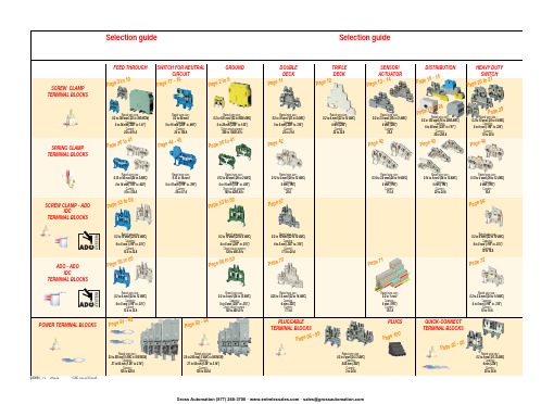
ABB EntrelecSommaireBU0402061SNC 160 003 C0205SummarySelection guide ....................................................................................page 1Screw clamp ........................................................................................page 2Feed through and ground terminal blocks .......................................................page 2 - 5 to 10Single pole, multiclamp terminal blocks..........................................................................page 4Feed through terminal blocks - Double-deck................................................................page 11Feed through terminal blocks - Triple-deck...................................................................page 12Three level sensor, terminal blocks without ground connection...................................page 13Three level sensor, terminal blocks with ground connection ........................................page 14Terminal blocks for distribution boxes, double deck + protection .......................page 15 - 16Interruptible terminal blocks for neutral circuit......................................................page 17 - 18Distribution : phase, ground terminal blocks .......................................................page 19 to 21Single pole or four pole distribution blocks..........................................................page 22 to 24Heavy duty switch terminal blocks with blade......................................................page 25 - 26Heavy duty switch terminal blocks with push-turn knob..............................................page 26Heavy duty switch terminal blocks with contact control pull lever...............................page 29Heavy duty switch terminal blocks with blade - Double-deck .....................................page 27Fuse holder terminal blocks for 5x20 mm (.197x.787 in.) and 5x25 mm (.197x.984 in.)or 6.35x25.4 mm (1/4x1 in.) and 6.35x32 mm (1/4x11/4 in.) fuse s.........................................page 28 - 29Fuse holder terminal blocks for 5x20 mm (.197x.787 in.) and 5x25 mm (.197x.984 in.) fuses -Double-dec k.....................................................................................................................page 27Terminal blocks for test circuits with sliding bridge ......................................................page 30Terminal blocks for metering circuits.............................................................................page 31ESSAILEC terminal blocks.............................................................................................page 32Safety connection terminal blocks ................................................................................page 33Miniblocks for EN 50045 (DIN 46277/2) rail ..........................................................page 34 - 35Spring clamp ......................................................................................page 36Angled terminal blocks - Feed through and ground .....................................................page 36Feed through and ground terminal blocks ...........................................................page 37 to 41Feed through terminal blocks - Double deck ................................................................page 42Terminal blocks for sensors / actuators ........................................................................page 42Terminal blocks for distribution boxes...........................................................................page 43Switch terminal blocks for neutral conductor........................................................page 44 - 45Heavy duty switch terminal blocks with blade..............................................................page 46Fuse holder terminal blocks for 5x20 mm (.197x.787 in.) and 5x25 mm (.197x.984 in.) fuse s....page 47Miniblocks Spring clamp ......................................................................................page 48 to 52ADO - Screw clamp ...........................................................................page 53Feed through and ground terminal blocks ...........................................................page 53 to 56Feed through and ground terminal blocks - Double-deck............................................page 57Heavy duty switch terminal blocks with blade..............................................................page 58Fuse holder terminal blocks for 5x20 mm (.197x.787 in.) and 5x25 mm (.197x.984 in.) fuse s ......page 59 - 60Miniblocks ADO - Screw clamp............................................................................page 61 to 65ADO - ADO .........................................................................................page 66Feed through and ground terminal blocks ...........................................................page 66 to 69Feed through and ground terminal blocks - Double-deck............................................page 70Terminal blocks for sensors / actuators ........................................................................page 71Heavy duty switch terminal blocks with blade..............................................................page 72Fuse holder terminal blocks for 5x20 mm (.197x.787 in.) and 5x25 mm (.197x.984 in.) fuse s ......page 73 - 74Miniblocks ADO - ADO .........................................................................................page 75 to 79Accessories ADO ...........................................................................................................page 80Power terminal blocks .............................................................page 81 to 84Quick-connect terminal blocks .................................................page 85 - 86Terminal blocks for railway applications ................................page 87 to 97Pluggable terminal blocks .....................................................page 98 to 100Accessories......................................................................................page 101Marking..................................................................................page 102 to 104GrossAutomation(877)268-3700··*************************PR30PR3.Z2PR3.G2PR5PR4PR1.Z2Rated wire size :Rated wire size :Rated wire size :Rated wire size :Mounting railsShield terminals forcollector barMarking tableHorizontal Rated wire size :0.5 to 16 mm² (22 to 8 AWG)Rated wire size :Rated wire size :Rated wire size :P a g e t o 29e30 t o 32ag e e3P a ge 8 t o 60a g e6t o 6574P a ge 7 t o 79P a ge 9P a g P a gGrossAutomation(877)268-3700··*************************2ABB Entrelecd010830402051SNC 160 003 C0205MA 2,5/5 - 2.5 mm² blocks - 5 mm .200" spacingAccessoriesGrossAutomation(877)268-3700··*************************3ABB Entrelec D010740402051SNC 160 003 C0205M 4/6 - 4 mm² blocks - 6 mm .238" spacingAccessoriesGrossAutomation(877)268-3700··*************************4ABB EntrelecD011030402051SNC 160 003 C0205M 4/6.3A - 4 mm² blocks - 6 mm .238" spacingM 4/6.4A - 4 mm² blocks - 6 mm .238" spacingGrossAutomation(877)268-3700··*************************5ABB Entrelec D010840402051SNC 160 003 C0205M 6/8 - 6 mm² blocks - 8 mm .315" spacingAccessoriesGrossAutomation(877)268-3700··*************************6ABB EntrelecD010850402051SNC 160 003 C0205M 10/10 - 10 mm² blocks - 10 mm .394" spacingAccessoriesGrossAutomation(877)268-3700··*************************7ABB Entrelec D010860402051SNC 160 003 C0205M 16/12 - 16 mm² blocks - 12 mm .473" spacingAccessoriesGrossAutomation(877)268-3700··*************************8ABB EntrelecD010870402051SNC 160 003 C0205M 35/16 - 35 mm² blocks - 16 mm .630" spacingGrossAutomation(877)268-3700··*************************M 95/26 - 95 mm² blocks - 26 mm 1.02" spacingM 70/22.P - 70 mm² ground block with rail contact - 22 mm .630" spacingSelection35 mm / 1.37"12 mm / 0.47"14-30 Nm / 124-260 Ib.in 1.2-1.4 Nm / 10.6-12.3 Ib.in1000600600415400400577070240 mm 2500 MCM 500 MCM 10 mm 2 6 AWG 6 AWG IEC UL CSANFC DIN0.5 - 160.5 - 100 AWG-600 MCM 2 AWG-500 MCM 50 - 30035 - 24018-6 AWGD 150/31.D10 - 150 mm² blocks - 31 mm 1.22" spacingCharacteristicsD 240/36.D10 - 240 mm² blocks - 36 mm 1.41" spacingSelectionWire size main circuit mm² / AWG VoltageV Current main circuit A Current outputARated wire size main circuit mm² / AWG Rated wire size outputmm² / AWG Wire stripping length main circuit mm / inches Wire stripping length output mm / inches Recommended torque main circuit Nm / Ib.in Recommended torque outputNm / Ib.inSolid Stranded Solid Stranded Wire size output mm² / AWG9.5 mm / .37"0.5-0.8 Nm / 4.4-7.1 Ib.in5003003003220204 mm 212 AWG12 AWG0.2 - 422-12 AWG 22-12 AWG 0.22 - 4IEC ULCSANFC DINCharacteristicsWire size mm² / AWGSolid Stranded D 4/6.T3 - 4 mm² blocks - 6 mm .238" spacingSelectionVoltage V CurrentARated wire sizemm² / AWG Wire stripping length mm / inches Recommended torqueNm / Ib.inM 4/6.T3.P - 4 mm² block - 6 mm .238" spacingD 2,5/6.D - 2.5 mm² blocks - 6 mm .238" spacingD 2,5/6.DL - 2.5 mm² blocks - 6 mm .238" spacingD 2,5/6.DPA1 - 2.5 mm² blocks - 6 mm .238" spacingD 2,5/6.DPAL1 - 2.5 mm² blocks - 6 mm .238" spacingD 4/6... - 4 mm² blocks - 6 mm .238" spacingD 4/6.LNTP - 4 mm² closed blocks - 17.8 mm .700" spacingMA 2,5/5.NT- 2.5 mm² block - 5 mm .200" spacingAccessories**SFB2 : 16 to 35 mm² 6 to 2 AWG H= 3 mm/.12"M 10/10.NT- 10 mm² block - 10 mm .394" spacingAccessories(1) Except for M 35/16 NT (closed block)*SFB1 : 0.5 to 35 mm² 18 to 2 AWG H= 7 mm/.28"**SFB2 : 16 to 35 mm² 6 to 2 AWG H= 3 mm/.12"MB 4/6... - 4 mm² blocks - 6 mm .238" spacingMB 6/8... - 6 mm² blocks - 8 mm .315" spacingMB 10/10... - 10 mm² blocks - 10 mm .394" spacingBRU 125 A - 35 mm² block - 27 mm 1.063" spacingBRU 160 A - 70 mm² block - 35.2 mm 1.388" spacingBRU 250 A - 120 mm² blocks - 44.5 mm 1.752" spacingBRU 400 A - 185 mm² block - 44.5 mm 1.752" spacingAccessoriesAccessoriesBRT 80 A - 16 mm² block - 48 mm 1.89" spacingBRT 125 A - 35 mm² block - 48 mm 1.89" spacingBRT 160 A - 50 mm² block - 50 mm 1.97" spacing9.5 mm / .37"0.5-0.6 Nm / 4.4-5.3 Ib.in4003003002010104 mm 210 AWG 12 AWG 0.5 - 422-10 AWG20-12 AWG0.5 - 2.5IEC ULCSANFC DINMA 2,5/5.SNB - 2.5 mm² blocks - 5 mm .200" spacingCharacteristicsM 4/6.SNB - 4 mm² blocks - 6 mm .238" spacingSelectionWire size mm² / AWGVoltage V CurrentARated wire sizemm² / AWG Wire stripping length mm / inches Recommended torqueNm / Ib.inSolid StrandedM 6/8.SNB - 6 mm² blocks - 8 mm .315" spacing - blade switchingSelectionAccessoriesM 4/8.D2.SF - for fuses 5x20 mm .197x.787 in. and 5x25 mm .197x.984 in. -4 mm² blocks - 8 mm .315" spacingM 4/6.D2.SNBT - 4 mm² blocks - 6 mm .238" spacing - blade switchM 4/8.SF- 4 mm² blocks - 8 mm .315" spacingM 4/8.SFL - 4 mm² blocks - 8 mm .315" spacing12 mm / .472"1.2-1.4 Nm / 10.6-12.3 Ib.in800(1)60060016252510 mm 210 AWG8 AWG0.5 - 1622-10 AWG 22-8 AWG 0.5 - 10IEC ULCSANFC DINCBD2SML 10/13.SF - for fuses 6.35x25.4 mm 1/4x1 in. and 6.35x32 mm 1/4x11/4 in. -10 mm² blocks - 13 mm .512" spacingSelectionAccessoriesCharacteristicsWire size mm² / AWGVoltage V CurrentARated wire sizemm² / AWG Wire stripping length mm / inches Recommended torqueNm / Ib.inSolid Stranded (1) Insulation voltage of terminal block - operating voltage : according to fuse.M 4/6.D2.2S2... - 4 mm² blocks - 6 mm .238" spacing11 mm / .43"0.8-1 Nm / 7.1-8.9 Ib.in50060030306 mm 28 AWG0.5 - 1022-8 AWG0.5 - 6IECULCSANFC DINM 6/8.ST... - 6 mm² blocks - 8 mm .315" spacingCharacteristicsWire size mm² / AWGVoltage V CurrentARated wire sizemm² / AWG Wire stripping length mm / inches Recommended torqueNm / Ib.inSolid Stranded M 6/8.STA - 6 mm² blocks - 8 mm .315" spacing(3)Only for M 6/8.STAM 4/6.ST- 4 mm² blocks - 6 mm .236" spacingBNT...PC...(2) Only for M10/10.ST-SnThe PREM IUM solution for testing the secondary circuits of current or voltage transformers.ESSAILEC, approved by the major electricity utilities, remains the premium choice for the energy market.Implemented in the transformers secondary circuits, ESSAILEC thanks to its intelligent “make before break” design eases and secures any intervention. Cutting the energy supply is avoided with zero risk for the operator.The plug and socket connection cuts cost installation as well as in-situ wiring errors. ESSAILEC is ideal for the wiring of sub-assemblies in the secondary circuits.ESSAILEC terminal blocksProtection relays,Protection relays,Testing :The ESSAILEC socket supplies energy to the protection or counting devices. The insertion of the test plug, which is connected to the measurement equipment, allows the testing of the devices, without perturbing the circuit.ESSAILEC blocks are well adapted to current or voltage measurement :-Current sockets with make before break contacts and pre-wired test plug for current measures-Voltage sockets with open contacts and pre-wired test plug for voltage measures-Up to 4 ammeters or 4 voltmeters connected to the test plugDistributing :The ESSAILEC plug is continuously mounted on the socket to supply current or voltage to secondary circuits sub assemblies.ESSAILEC blocks extreme versatility allow :-Safe current distribution with current socket with mobile contacts since the secondary circuit is not cut when plug is removed-Voltage or polarity distribution with dedicated voltage or polarity socket with closed contactESSAILEC is designed to offer :Great flexibility :-Connection multi contacts « plug and play »-Panel, rail, rack fixed mounting or stand-alone connector -Two wiring technologies, up to 10 mm²Extreme reliability :-Non symmetric blocks -Coding accessories -IP20 design -Locking system -Sealed coverR S T NFor technical characteristics and complete part numbers list, please ask for the ESSAILEC catalog10005006003225254 mm 21.65 mm²12 AWG 13 mm / .51"IECB.SCSANFC DINTS 50-180.5 - 0.8 Nm /4.4 - 7.1 Ib.in0.2 - 422-12 AWG0.22 - 40.5 - 1.50.28 - 1.6580050060041252562.512 AWG 13 mm / .51"0.8 - 1 Nm / 7.1 - 8.9 Ib.inIECB.S CSANFC DINTS 50-180.5 - 1020-12 AWG0.5 - 60.28 - 2.590050060046406510 mm 26 mm² 6 AWG 14 mm / .55"IECB.S UL/CSANFC DINTS 50-181.2 - 1.4 Nm / 10.6 - 12.3 Ib.in0.5 - 1620 - 6 AWG0.5 - 100.28 - 6M 4/6.RS - 4 mm² blocks - 6 mm .238" spacingCharacteristicsWire size mm² / AWGVoltage V CurrentARated wire sizemm² / AWG Wire stripping lengthmm / inches Recommended torque (screw)Nm / Ib.inSolid wire Stranded wire Solid wire Stranded wire Screw clampLugsM 6/8.RS - 6 mm² blocks - 8 mm .315" spacingCharacteristicsWire size mm² / AWGVoltage V CurrentARated wire sizemm² / AWG Wire stripping lengthmm / inches Recommended torque (screw)Nm / Ib.inSolid wire Stranded wire Solid wire Stranded wire Screw clampLugspending M 10/10.RS - 10 mm² blocks - 10 mm .394" spacingCharacteristicsWire size mm² / AWGVoltage V CurrentARated wire sizemm² / AWG Wire stripping lengthmm / inches Recommended torque (screw)Nm / Ib.inSolid wire Stranded wire Solid wire Stranded wire Screw clampLugspending SelectionAccessories(1) Only for block M 4/6.RS (4) For blocks M 4/6.RS and M 6/8.RS(2) Only for block M 6/8.RS(3) Only for block M 10/10.RSDR 1,5/4 - 1.5 mm² blocks - 4 mm .157" spacingDR 1,5/5... - 1.5 mm² blocks - 5 mm .200" spacing。
斑马技术公司DS8108数字扫描仪产品参考指南说明书

博伊英工组合777-2飞机系统说明书

Aerospace Capabilities Boeing 7772 EATON Aerospace Group CF-21B April 2014The Boeing 777 is equipped with three hydraulic systems. The left, center and right sys-tems deliver hydraulic fluid at a rated pressure of 3000 psig (207 bar) to operate flight con-trols, flap systems, actuators, landing gear and brakes.Primary hydraulic power for the left and right systems isprovided by two engine-driven pumps (EDP) and supplemented by two on-demand electric motor-driven pumps (ACMP) manufactured by Eaton.Two Eaton on-demand air tur-bine-driven pumps (ADP) power the center system. There are also two Eaton primary electric motorpumps (ACMP) that pro-vides hydraulic power for the engine thrust reversers, primary flight controls, landing gear and flaps/slats in the center system.Under emergency conditions hydraulic power is generated by the ram air turbine (RAT) which is deployed automatically and drives an Eaton variable dis-placement inline pump. The RAT pump provides flow to the center system flight controls.Eaton supplies many critical electro-mechanical actuators for the 777. Eaton provides door mechanisms that consist of flight locks on the eightpassenger doors, power drive units to operate the two large cargo doors, rotary actuators to latch the two large cargo doors and a power drive unit to operate the small cargo door. The 777 also utilizes two thrust reverse interlock linear actuators and an auto speed brake control stand linear actuator. Eaton alsosupplies the Environmental Control System (ECS) dooractuator that will operate the ECS door in flight to control airflow to the ECS system. The 777 contains an Eaton rudder trim switch to control the position of the rudder trim actuator. The Boeing 777 equipped with GE90 Snecma engines utilize the advance technology of Eaton's Quantitative Debris Monitoring (QDM) system. The QDM is an early warning for potential gear or bearing failure by capturing and indicating the presence of ferrous debris parti-cles in the lube oil. The unit is mounted in a Lubriclone ® that effectively separates air from the oil before returning oil to the lube tank.Eaton chip collectors are on the engines and manual level indica-tors in many of the secondary power systems.Each hydraulic system utilizes Eaton's integrated hydraulic fil-ter module, which performs the critical task of filtering pressure and case drain hydraulic fluid for use in the hydraulic system.Within the center system, Eaton's brake metering valve (BMV) controls hydraulic pres-sure to the aircraft brakes.Eaton's main landing gear priori-ty valve (MLGPV) performs a critical function during peak hydraulic power demands, such as landing. Also, playing a criti-cal role in aircraft safety, Eaton's emergency passenger door actuator (EPDA) assembly is used to open a door when acti-vated by nitrogen gas pressure.Eaton’s Aeroquip ® product line includes the fluid quick discon-nect coupling and self-sealing "B" nut fittings that are used in the Boeing 777 hydraulic sys-tem. They are also integrated in the hose assemblies reducing weight and eliminating potential leak paths on the aircraft. Other Eaton products included on the 777 are main engine fuel pumps, pressure refueling level control valves and special main landing gear swivels that were designed to meet the additional side loads during deployment of the landing gear.The Boeing 777 is a wide-body, twin-engine airplane with flexibility in range, routes and interior configurations. Its state-of-the-art technology includes fly-by-wire flight controls and digital avionics.Similar in appearance to the 767, the Boeing 777 is longer and wider with wings that include a folding wing-tip option. The landing gear on the 777 is the largest ever incorporated into acommercial airplane to date. The standard two-post arrangement features six-wheel trucks instead ofconventional four-wheel units. A total of 12 wheels support the 777 for better weight distribution during landing and while taxing to terminals. The cantilever low swept-wing design monoplane is of advanced construction, with a cockpit based on the 747.The 777 is powered by General Electric, Pratt & Whitney and Rolls Royce engines ranging from 74,000 lbs to 122,965 lbs of thrust. The wide body twin-engine aircraft can carry between 305 and 440 passengers, seating ranges from six to ten abreast with two aisles and has a range of 7,250 to 8,820nautical miles while traveling at Mach 0.84.Boeing 777 System OverviewEaton’s Aerospace Product CapabilitiesEATON Aerospace Group CF-21B April 2014 3Engine Solutions13.Low Profile, Self-Sealing Fittings 14.Kevlar ® Hose Assembly15.Low Profile Ratchet Lock Couplings16.Low Profile Ball Bearing Plane Swivel Joints 17.Absolute/Gauge Pressure Switch 18.Pressure Altitude Switch 19.Differential Pressure Switch 20.Sight Gauge 21.Chip Collector22.Quantitative Debris Monitor 23.Lubriclone24.Prismlite Level IndicatorHydraulic Systems25.Engine-Driven Pumps 26.Air-Driven Pumps 27.Inline Motor28.Fluid Cooled AC Motorpumps 29.Rotary Actuator30.Brake Metering Valves31.Main Landing Gear Priority Valve 32.Filter Modules 33.Solenoid Valves 34.Shut-Off Reservoirs35.Priority/Flow Limiting Valve 36Stabilizer Trim Motor 37.Ram Air Turbine PumpFuel Systems11.Main Engine Fuel Pumps12.Pressure Refueling Level Control ValveMotion Control1.Flight Lock Actuator2.Thrust Reverse Interlock Actuator3.Auto Speed Brake Control Stand Acutator4.Pneumatic Actuators5.Cargo Door Rotary Actuator6.Lift Latch Power Drive Unit7.Power Drive Unit Assembly8.Rudder Trim Switch9.Environmental Control System Door Actuator 10.Emergency Passenger Door Actuator11023456789111213141516171819202122232425262728293031323334353637Eaton’s Boeing 777 Components4 EATON Aerospace Group CF-21B April 2014MF1-095-6Stabilizer T rim MotorEaton’s Stabilizer Trim Motor is a 3000 psi (207 bar), 2320 rpm bent axis fixed stroke piston motor. Displacement is 0.803 cu in/rev (12.15 ml/rev). Dry motor weight is 9.75 lbs (4.42kg)PV3-115-34Ram Air T urbine PumpEaton's 3025 psi (208 bar) inline piston pump provides 20 gpm (76 L/min) at 3920 rpm hydraulic power for the priority flight con-trol surfaces in the event power is lost in both engines or a total electric power failure occurs. Displacement is 1.25 cu in/rev (20.47 ml/rev). Dry pump weight is 15 lbs (6.8 kg).PV3-300-16Main System Engine and Air Motor Driven PumpHydraulic power for the left and right systems is supplied by two 48 gpm (182 L/min), 4315 rpm, variable displacement, 3000 psi (207 bar), pressure compensated inline pumps. Displacement is 3.0 cu.in./rev. (49.14 ml/rev). Dry pump weight is 40.10 lbs (18.18 kg).MPEV3-040-10AC MotorpumpAuxiliary power is provided by a 3110 psi (214 bar), 12 gpm (45 L/min), 8000 rpm, fluid cooled motorpump. Features include ceramic electrical feed through design and a non-metallic diffuser. Eaton's integrated motorpump completed the longest qualification test on a single product in the history of Eaton's Vickers ®product line.1800 & 1801 SeriesLow Profile Ratchet Lock CouplingsEaton’s Aeroquip product line of self-sealing ratchet lock couplings offer dependable service in aircraft for both low and high pressure applications. These couplings are available in both aluminum and stainless steel.Low Profile Ball Bearing PlaneSwivel JointsTo meet the demanding side load requirements on the Boeing 777 landing gear, Eaton has improved the performance of the 1817 Series low profile ball bearing plane swivel joints to take up to three times the MIL-J-5514 side load requirements. The resulting swivel design has superior reli-ability and ultra low swiveltorque.AS1975 & AS4623 Kevlar ® Hose AssembliesEaton’s Kevlar hose assemblies optimize weight throughout thehydraulic system.AS1896Low Profile, Self-Sealing Hydraulic "B" Nut Fittings Eaton combined a small enve-lope size with minimal weight to develop the low profile, self-seal-ing hydraulic "B" nut fittings. The "B" nut design is for both high and low pressure hydraulic sys-tems on the Boeing 777.EATON Aerospace Group CF-21B April 2014571425Filter ModuleThe Boeing 777 integrates Eaton's hydraulic filter module within each of the three main hydraulic systems. The module fil-ters the pressure and case drain hydraulic fluid for use in the hydraulic system. System pres-sure is monitored and controlled through a series of integrated valves, sensors, pressure trans-ducers, check valves, and relief valves. Also provided are ground service connections.71404Brake Metering ValveEaton’s brake metering valve controls hydraulic pressure to the aircraft brakes. Using spool and sleeve technology, the brake valve has two separate normally-closed metering valves, a de-spin actuator, and a common input shaft for both metering valves. The metering valve for the left hydraulic system is opened by rotation of the input shaft or for the right system by actuation of the de-spin actuator.71476Emergency Passenger Door ActuatorPlaying a critical role in aircraft safety, the emergency passenger door actuator assembly extends to open a door when actuated by nitrogen gas pressure. Eaton's actuator extends 4.44 inches (113mm) (minimum) to open the door when gas is applied at the inlet fitting. Maximum inletpressure is 4125 psig (284 bar). The assembly will reach fullextension in 2.75 to 4.16 seconds with an output force of 2507 to 2830 lbs (1137 to 1284 kg).71444Main Landing Gear Priority ValveInstalled within the main landing gear hydraulic system, this valve performs a critical functionduring periods of peak hydraulic power demands. The lap assembly piston, spool and sleeve valve is a pressure sensitive flow limiter with a solenoid over-ride feature. With the solenoid de-energized, the valve senses control pressure and responds byrestricting flow from fully open at 2475 psi (171 bar) to fully restricted at 2000 psi (138 bar). Flow at the restricted position is 1.0-1.2 gpm (3.79 - 4.54 L/min.).211C223 Series Pressure SwitchEaton’s small, lightweight,pressure switches are designed for use in any fluid that iscompatible with stainless steel, aluminum or titanium. Typical fluid applications includehydraulic oils per MIL-H-5606 and MIL-H-83282, Phosphate Ester, AO2-CTFE and water. The Eaton pressure switch design incorporates a snap-actionelectrical microswitch, which is actuated by a piston-sensing element. The snap-spring design is very reliable and has excellent vibration resistance.214C40 SeriesPressure Altitude Switch This small, lightweight altitude switch can be set to actuate at any altitude from -1,000 feet(15.25 psia/1.05 bar) to 70,000 feet (.649 psia/.045 bar). Qualified to MIL-STD-810C, its performance and reliability are assured. The 214C40 Series switch utilizes an aneroid-type capsule, which operates a snap-action electrical switch. The 214C40 can be used for gas density and hashermetically sealed electrical contacts.21C1 Series Absolute/Gauge Pressure SwitchEaton's 21C1 type pressure switches have all-welded, stain-less steel construction suitable for use with most corrosive media, including lube oils, hydraulic fluids, fuels, air and others. Wetted materials are 300 series stainless steel. The switch with a pressure-sensing element stainless steel diaphragm. The absolute pressuretype switch is hermetically sealed.21SN04 SeriesDifferential Pressure Switch Eaton's 21SN04 differentialpressure switch is an all-welded, stainless steel snap-actionpressure element, hermetically sealed switch that operates up to 400°F (205°C) for system pressures to 750 psi (52 bar). The switch meets flame-proof requirements of commercial aircraft and is lightweight, compact and rugged.The switch may be used to detect fuel or oil filter clogging or to detect low-fuel booster pump pressure and closing andwarning indicator circuit.6 EATON Aerospace GroupCF-21B April 2014692D100Rotary Actuator for Large Cargo DoorEaton's rotary actuators are de- signed to provide maximum weight to power efficiency for operation in harsh environments. The design options include potentiometer, synchro, resolver or RVDT feedback, mechanical overrides and redundant motors.931D100Lift Latch Power Drive UnitThis actuator consists of anAC 3-phase brushless motor with integral brake, a primary torque limiting device, a manual drive provision with torque limiter and six stages of reduction gearing, resulting in a final drive ratio of 1572.34 to 1. Extremely powerful for its size, this unit functions in aload range of between 9500 in lbs to 14,000 in lbs. Full extend orretract time is under 8 seconds.684D100Thrust Reverse Interlock ActuatorEaton's model 684D100 oper-ates the speed brake spoilers on the Boeing 777. The ThrustReverse Interlock Actuator has a 28 VDC reversible design with intermittent duty and integral brake. It has non-jammingmechanical stops with adjustable limit switches and a ball screw design with anti-rotation for bet-ter performance. The standard operating load for this unit is 140 lbs. (63.5 kg) and a maximum load of 350 lbs. (158 kg).924D100Auto Speed Brake Control Stand ActuatorThe Eaton linear actuator is a component of the speed brake system. The device functions on command from the Primary Flight Computer (PFC). At land-ing touchdown, the PFC sends an extend command to the Actuator Control Electronics (ACE) that signals the ACE to provide power to the actuator. The actuator drives the speed brake handle and speed brake transducer to the extend posi-tion. The resulting transducer change signals the ACE to pro-vide power to the spoiler actua-tors to fully extend the spoilersfor ground speed braking.2D6559Prismalite ®Prismalite is a level indicator probe inserted in a tank or housing to indicate the pres-ence of a liquid at a fixed level. Manual inspection will reveal all incident light when the point is not covered and a dark condi-tion when liquid covering the point refracts the incident light into the liquid. Can be mounted in any orientation.1L2984/1C2977-2Quantitative Debris Monitor System & Lubriclone ®Eaton's QDM ® generates an electrical pulse proportional to the mass of ferrous wear parti-cles to signal an early warning of potential failure of lubricated engine gears and bearings. The sensor is mounted in a Lubriclone ® cyclonic separator that removes entrained air from the scavenged oil while providing a quiescent area for the sensor to capture the debris with high efficiency.1A6473Chip CollectorEaton’s chip collector probe is installed in the lube oil system of an engine or gearbox to trap, magnetically, any ferrous parti-cles generated by wear in bear-ings or gears. Manual examina-tion of the debris is required to determine the extent of dam-age.2D666BSight GaugeEaton’s sight gauge mounted to the exterior of a tank or housing to providevisual indication of a liquidover a wide range.933D100Flight Lock ActuatorEaton's 28VDC linear actuator operates the eight in-flight passenger door locks on the Boeing 777 aircraft. The rated operation load for this unit is 8.0 lbs (3.48 kg) and a maximum static load of 100 lbs (43.5 kg). The motor is designed for continuous stall and has anintegral clutch design. 964D100Power Drive Unit Assembly This Eaton Power Drive Unit (PDU) lift/latch actuation system operates the small cargo doors. It unlatches and translates (lifts) the door in an upward direction, clear of the stop fittings. At this point, the Hinge Drive System (HDS) can continue opening the door by rotating it upward and outward. The 964D100 is equipped for backup (manual)operation. 138400ECS Door ActuatorSold to Hamilton-Sundstrand, this compact linear actuator operates (opens and closes) the fresh air intake door in their Environmental ControlSystem (ESC).SummaryEaton’s Aerospace ProductsMODEL PART NUMBER DESCRIPTION933D100 S135W171-1 Flight Lock Actuator684D100 S253T402-4 Thrust Reverse Interlock Actuator924D100 S254W911-1 Auto Speed Brake Control Stand Actuator 692D100 S135W132-3 Rotary Actuator For Large Cargo Door931D100 S135W160-3 Lift Latch Power Drive Unit964D100 S135W261-1 Power Drive Unit Assembly6707 S231W262-1 Rudder Trim Switch138400 ECS Door Actuator71476 S131W187-4 Emergency Passenger Door Actuator71425 S271W221-1 Filter Module71404 294W1111-4 Brake Metering Valve71444 S271W814-1 Main Landing Gear Priority ValveMF1-095-6 342381 Stabilizer Trim MotorMPEV3-040-10 848037 AC MotorpumpPV3-115-34 848330 Ram Air Turbine PumpPV3-300-16 847999 Main System Engine & Air Driven PumpAS1896 Low Profile, Self-Sealing “B” Nuts Fittings AS1975 & AS4623 Kevlar® Hose Assemblies1800 & 1801 Series Low Profile Ratchet Lock Couplings1817 Series Low Profile Ball Bearing Plane Swivel Joints 21C1 Series Absolute/Gauge Pressure Switch211C223 Series Pressure Switch214C40 Series Pressure Altitude Switch21SN04 Series Differential Pressure Switch2D666B Sight Gauge1A6473 Chip Collector1L2984 Quantitative Debris Monitor System1C2977-2 Lubriclone®2D6559 Prismalite Level Indicator721400/72330/828500/830800 Main Gear Fuel Pumps8410 568-1-27202 Fuel Boost Pump8411568-1-27203 CanisterT ype 8410 Fuel Boost Pumpand T ype 8411 CanisterEaton's canister-mounted fuelboost pump was designed forthe A320 to provide exceptionalperformance for high climb ratesand at high cruising altitudes.EATON Aerospace Group CF-21B April 2014 7Copyright © 2014 EatonAll Rights ReservedCopying or Editing is Forbidden Form No. C5-21BApril 2014EatonAerospace Group9650 Jeronimo Road Irvine, CA 92618tel: (949) 452-9500fax: (949) 452-9555 /aerospace。
DELTA ASDA-B2系列伺候驱动器 简易说明书
目錄第一章產品檢查與型號說明1.1 產品檢查..........................................................................................................1-1 1.2 產品型號對照 ..................................................................................................1-21.2.1 銘牌說明.................................................................................................1-21.2.2 型號說明.................................................................................................1-3 1.3 伺服驅動器與馬達機種名稱對應參照表...........................................................1-5 1.4 伺服驅動器各部名稱........................................................................................1-6 1.5 伺服驅動器操作模式簡介.................................................................................1-7 第二章 規格2.1 伺服驅動器標準規格(ASDA-B2系列).........................................................2-1 2.2 伺服馬達標準規格(ECMA系列)..................................................................2-3 2.3 轉矩特性(T-N曲線).....................................................................................2-7 2.4 過負載之特性...................................................................................................2-8 2.5 伺服驅動器外型尺寸........................................................................................2-10 2.6 伺服馬達外型尺寸............................................................................................2-14 2.7回生電阻的選擇方法.................................................................................................2-17 第三章 配線3.1 週邊裝置與主電源迴路連接.............................................................................3-13.1.1 週邊裝置接線圖......................................................................................3-1 Revision July, 2010目錄|Revision July, 20103.1.2 驅動器的連接器與端子...........................................................................3-33.1.3 電源接線法 ............................................................................................3-43.1.4 馬達U 、V 、W 引出線的連接頭規格......................................................3-53.1.5 編碼器引出線的連接頭規格....................................................................3-73.1.6 線材的選擇..............................................................................................3-83.2 伺服系統基本方塊圖........................................................................................3-93.2.1 400W (含)以下機種(無內含回生電阻)............................................3-93.2.2 750W 機種(內含回生電阻,無風扇)..................................................3-103.2.3 1kW ~ 1.5kW 機種(內含回生電阻和風扇)..........................................3-113.2.4 2kW ~ 3kW 機種(內含回生電阻和風扇).............................................3-123.3 CN1 I/O 信號接線............................................................................................3-133.3.1 CN1 I/O 連接器端子Layout....................................................................3-133.3.2 CN1 I/O 連接器信號說明........................................................................3-153.3.3 介面接線圖(CN1)...............................................................................3-223.3.4 使用者指定DI 與DO 信號......................................................................3-273.4 CN2編碼器信號接線.......................................................................................3-283.5 CN3通訊埠信號接線.......................................................................................3-303.5.1 CN3通訊埠端子Layout..........................................................................3-303.5.2 CN3通訊埠與個人電腦之連接方式........................................................3-313.6 標準接線方式...................................................................................................3-323.6.1 位置(Pt )模式標準接線........................................................................3-323.6.2 速度模式標準接線...................................................................................3-333.6.3 扭矩模式標準接線...................................................................................3-34目錄|第四章 參數與功能4.1 參數定義..........................................................................................................4-1 4.2 參數一覽表.......................................................................................................4-2 4.3 參數說明..........................................................................................................4-12P0-xx 監控參數.................................................................................................4-12 P1-xx 基本參數.................................................................................................4-20 P2-xx 擴充參數.................................................................................................4-39 P3-xx 通訊參數.................................................................................................4-60 P4-xx 診斷參數.................................................................................................4-64 表4.1 數位輸入(DI)功能定義表....................................................................4-72 表4.2 數位輸出(DO)功能定義表..................................................................4-76 第五章異警排除5.1 驅動器異警一覽表............................................................................................5-1 5.2 異警原因與處置...............................................................................................5-3 5.3 發生異常後解決異警之方法.............................................................................5-10Revision July, 2010目錄|(此頁有意留為空白)Revision July, 2010第一章產品檢查與型號說明1.1 產品檢查為了防止本產品在購買與運送過程中的疏忽,請詳細檢查下表所列出的項目:檢查項目內容是否為所欲購買的產品分別檢查馬達與驅動器銘版上的產品型號,可參閱1.2節所列的型號說明馬達轉軸是否運轉平順用手旋轉馬達轉軸,如果可以平順運轉,代表馬達轉軸是正常的。
Glider Flying Handbook说明书
Glider Flying Handbook2013U.S. Department of TransportationFEDERAL AVIATION ADMINISTRATIONFlight Standards Servicei iPrefaceThe Glider Flying Handbook is designed as a technical manual for applicants who are preparing for glider category rating and for currently certificated glider pilots who wish to improve their knowledge. Certificated flight instructors will find this handbook a valuable training aid, since detailed coverage of aeronautical decision-making, components and systems, aerodynamics, flight instruments, performance limitations, ground operations, flight maneuvers, traffic patterns, emergencies, soaring weather, soaring techniques, and cross-country flight is included. Topics such as radio navigation and communication, use of flight information publications, and regulations are available in other Federal Aviation Administration (FAA) publications.The discussion and explanations reflect the most commonly used practices and principles. Occasionally, the word “must” or similar language is used where the desired action is deemed critical. The use of such language is not intended to add to, interpret, or relieve a duty imposed by Title 14 of the Code of Federal Regulations (14 CFR). Persons working towards a glider rating are advised to review the references from the applicable practical test standards (FAA-G-8082-4, Sport Pilot and Flight Instructor with a Sport Pilot Rating Knowledge Test Guide, FAA-G-8082-5, Commercial Pilot Knowledge Test Guide, and FAA-G-8082-17, Recreational Pilot and Private Pilot Knowledge Test Guide). Resources for study include FAA-H-8083-25, Pilot’s Handbook of Aeronautical Knowledge, FAA-H-8083-2, Risk Management Handbook, and Advisory Circular (AC) 00-6, Aviation Weather For Pilots and Flight Operations Personnel, AC 00-45, Aviation Weather Services, as these documents contain basic material not duplicated herein. All beginning applicants should refer to FAA-H-8083-25, Pilot’s Handbook of Aeronautical Knowledge, for study and basic library reference.It is essential for persons using this handbook to become familiar with and apply the pertinent parts of 14 CFR and the Aeronautical Information Manual (AIM). The AIM is available online at . The current Flight Standards Service airman training and testing material and learning statements for all airman certificates and ratings can be obtained from .This handbook supersedes FAA-H-8083-13, Glider Flying Handbook, dated 2003. Always select the latest edition of any publication and check the website for errata pages and listing of changes to FAA educational publications developed by the FAA’s Airman Testing Standards Branch, AFS-630.This handbook is available for download, in PDF format, from .This handbook is published by the United States Department of Transportation, Federal Aviation Administration, Airman Testing Standards Branch, AFS-630, P.O. Box 25082, Oklahoma City, OK 73125.Comments regarding this publication should be sent, in email form, to the following address:********************************************John M. AllenDirector, Flight Standards Serviceiiii vAcknowledgmentsThe Glider Flying Handbook was produced by the Federal Aviation Administration (FAA) with the assistance of Safety Research Corporation of America (SRCA). The FAA wishes to acknowledge the following contributors: Sue Telford of Telford Fishing & Hunting Services for images used in Chapter 1JerryZieba () for images used in Chapter 2Tim Mara () for images used in Chapters 2 and 12Uli Kremer of Alexander Schleicher GmbH & Co for images used in Chapter 2Richard Lancaster () for images and content used in Chapter 3Dave Nadler of Nadler & Associates for images used in Chapter 6Dave McConeghey for images used in Chapter 6John Brandon (www.raa.asn.au) for images and content used in Chapter 7Patrick Panzera () for images used in Chapter 8Jeff Haby (www.theweatherprediction) for images used in Chapter 8National Soaring Museum () for content used in Chapter 9Bill Elliot () for images used in Chapter 12.Tiffany Fidler for images used in Chapter 12.Additional appreciation is extended to the Soaring Society of America, Inc. (), the Soaring Safety Foundation, and Mr. Brad Temeyer and Mr. Bill Martin from the National Oceanic and Atmospheric Administration (NOAA) for their technical support and input.vv iPreface (iii)Acknowledgments (v)Table of Contents (vii)Chapter 1Gliders and Sailplanes ........................................1-1 Introduction....................................................................1-1 Gliders—The Early Years ..............................................1-2 Glider or Sailplane? .......................................................1-3 Glider Pilot Schools ......................................................1-4 14 CFR Part 141 Pilot Schools ...................................1-5 14 CFR Part 61 Instruction ........................................1-5 Glider Certificate Eligibility Requirements ...................1-5 Common Glider Concepts ..............................................1-6 Terminology...............................................................1-6 Converting Metric Distance to Feet ...........................1-6 Chapter 2Components and Systems .................................2-1 Introduction....................................................................2-1 Glider Design .................................................................2-2 The Fuselage ..................................................................2-4 Wings and Components .............................................2-4 Lift/Drag Devices ...........................................................2-5 Empennage .....................................................................2-6 Towhook Devices .......................................................2-7 Powerplant .....................................................................2-7 Self-Launching Gliders .............................................2-7 Sustainer Engines .......................................................2-8 Landing Gear .................................................................2-8 Wheel Brakes .............................................................2-8 Chapter 3Aerodynamics of Flight .......................................3-1 Introduction....................................................................3-1 Forces of Flight..............................................................3-2 Newton’s Third Law of Motion .................................3-2 Lift ..............................................................................3-2The Effects of Drag on a Glider .....................................3-3 Parasite Drag ..............................................................3-3 Form Drag ...............................................................3-3 Skin Friction Drag ..................................................3-3 Interference Drag ....................................................3-5 Total Drag...................................................................3-6 Wing Planform ...........................................................3-6 Elliptical Wing ........................................................3-6 Rectangular Wing ...................................................3-7 Tapered Wing .........................................................3-7 Swept-Forward Wing ..............................................3-7 Washout ..................................................................3-7 Glide Ratio .................................................................3-8 Aspect Ratio ............................................................3-9 Weight ........................................................................3-9 Thrust .........................................................................3-9 Three Axes of Rotation ..................................................3-9 Stability ........................................................................3-10 Flutter .......................................................................3-11 Lateral Stability ........................................................3-12 Turning Flight ..............................................................3-13 Load Factors .................................................................3-13 Radius of Turn ..........................................................3-14 Turn Coordination ....................................................3-15 Slips ..........................................................................3-15 Forward Slip .........................................................3-16 Sideslip .................................................................3-17 Spins .........................................................................3-17 Ground Effect ...............................................................3-19 Chapter 4Flight Instruments ...............................................4-1 Introduction....................................................................4-1 Pitot-Static Instruments ..................................................4-2 Impact and Static Pressure Lines................................4-2 Airspeed Indicator ......................................................4-2 The Effects of Altitude on the AirspeedIndicator..................................................................4-3 Types of Airspeed ...................................................4-3Table of ContentsviiAirspeed Indicator Markings ......................................4-5 Other Airspeed Limitations ........................................4-6 Altimeter .....................................................................4-6 Principles of Operation ...........................................4-6 Effect of Nonstandard Pressure andTemperature............................................................4-7 Setting the Altimeter (Kollsman Window) .............4-9 Types of Altitude ......................................................4-10 Variometer................................................................4-11 Total Energy System .............................................4-14 Netto .....................................................................4-14 Electronic Flight Computers ....................................4-15 Magnetic Compass .......................................................4-16 Yaw String ................................................................4-16 Inclinometer..............................................................4-16 Gyroscopic Instruments ...............................................4-17 G-Meter ........................................................................4-17 FLARM Collision Avoidance System .........................4-18 Chapter 5Glider Performance .............................................5-1 Introduction....................................................................5-1 Factors Affecting Performance ......................................5-2 High and Low Density Altitude Conditions ...........5-2 Atmospheric Pressure .............................................5-2 Altitude ...................................................................5-3 Temperature............................................................5-3 Wind ...........................................................................5-3 Weight ........................................................................5-5 Rate of Climb .................................................................5-7 Flight Manuals and Placards ..........................................5-8 Placards ......................................................................5-8 Performance Information ...........................................5-8 Glider Polars ...............................................................5-8 Weight and Balance Information .............................5-10 Limitations ...............................................................5-10 Weight and Balance .....................................................5-12 Center of Gravity ......................................................5-12 Problems Associated With CG Forward ofForward Limit .......................................................5-12 Problems Associated With CG Aft of Aft Limit ..5-13 Sample Weight and Balance Problems ....................5-13 Ballast ..........................................................................5-14 Chapter 6Preflight and Ground Operations .......................6-1 Introduction....................................................................6-1 Assembly and Storage Techniques ................................6-2 Trailering....................................................................6-3 Tiedown and Securing ................................................6-4Water Ballast ..............................................................6-4 Ground Handling........................................................6-4 Launch Equipment Inspection ....................................6-5 Glider Preflight Inspection .........................................6-6 Prelaunch Checklist ....................................................6-7 Glider Care .....................................................................6-7 Preventive Maintenance .............................................6-8 Chapter 7Launch and Recovery Procedures and Flight Maneuvers ............................................................7-1 Introduction....................................................................7-1 Aerotow Takeoff Procedures .........................................7-2 Signals ........................................................................7-2 Prelaunch Signals ....................................................7-2 Inflight Signals ........................................................7-3 Takeoff Procedures and Techniques ..........................7-3 Normal Assisted Takeoff............................................7-4 Unassisted Takeoff.....................................................7-5 Crosswind Takeoff .....................................................7-5 Assisted ...................................................................7-5 Unassisted...............................................................7-6 Aerotow Climb-Out ....................................................7-6 Aerotow Release.........................................................7-8 Slack Line ...................................................................7-9 Boxing the Wake ......................................................7-10 Ground Launch Takeoff Procedures ............................7-11 CG Hooks .................................................................7-11 Signals ......................................................................7-11 Prelaunch Signals (Winch/Automobile) ...............7-11 Inflight Signals ......................................................7-12 Tow Speeds ..............................................................7-12 Automobile Launch ..................................................7-14 Crosswind Takeoff and Climb .................................7-14 Normal Into-the-Wind Launch .................................7-15 Climb-Out and Release Procedures ..........................7-16 Self-Launch Takeoff Procedures ..............................7-17 Preparation and Engine Start ....................................7-17 Taxiing .....................................................................7-18 Pretakeoff Check ......................................................7-18 Normal Takeoff ........................................................7-19 Crosswind Takeoff ...................................................7-19 Climb-Out and Shutdown Procedures ......................7-19 Landing .....................................................................7-21 Gliderport/Airport Traffic Patterns and Operations .....7-22 Normal Approach and Landing ................................7-22 Crosswind Landing ..................................................7-25 Slips ..........................................................................7-25 Downwind Landing ..................................................7-27 After Landing and Securing .....................................7-27viiiPerformance Maneuvers ..............................................7-27 Straight Glides ..........................................................7-27 Turns.........................................................................7-28 Roll-In ...................................................................7-29 Roll-Out ................................................................7-30 Steep Turns ...........................................................7-31 Maneuvering at Minimum Controllable Airspeed ...7-31 Stall Recognition and Recovery ...............................7-32 Secondary Stalls ....................................................7-34 Accelerated Stalls .................................................7-34 Crossed-Control Stalls ..........................................7-35 Operating Airspeeds .....................................................7-36 Minimum Sink Airspeed ..........................................7-36 Best Glide Airspeed..................................................7-37 Speed to Fly ..............................................................7-37 Chapter 8Abnormal and Emergency Procedures .............8-1 Introduction....................................................................8-1 Porpoising ......................................................................8-2 Pilot-Induced Oscillations (PIOs) ..............................8-2 PIOs During Launch ...................................................8-2 Factors Influencing PIOs ........................................8-2 Improper Elevator Trim Setting ..............................8-3 Improper Wing Flaps Setting ..................................8-3 Pilot-Induced Roll Oscillations During Launch .........8-3 Pilot-Induced Yaw Oscillations During Launch ........8-4 Gust-Induced Oscillations ..............................................8-5 Vertical Gusts During High-Speed Cruise .................8-5 Pilot-Induced Pitch Oscillations During Landing ......8-6 Glider-Induced Oscillations ...........................................8-6 Pitch Influence of the Glider Towhook Position ........8-6 Self-Launching Glider Oscillations During Powered Flight ...........................................................8-7 Nosewheel Glider Oscillations During Launchesand Landings ..............................................................8-7 Tailwheel/Tailskid Equipped Glider Oscillations During Launches and Landings ..................................8-8 Aerotow Abnormal and Emergency Procedures ............8-8 Abnormal Procedures .................................................8-8 Towing Failures........................................................8-10 Tow Failure With Runway To Land and Stop ......8-11 Tow Failure Without Runway To Land BelowReturning Altitude ................................................8-11 Tow Failure Above Return to Runway Altitude ...8-11 Tow Failure Above 800' AGL ..............................8-12 Tow Failure Above Traffic Pattern Altitude .........8-13 Slack Line .................................................................8-13 Ground Launch Abnormal and Emergency Procedures ....................................................................8-14 Abnormal Procedures ...............................................8-14 Emergency Procedures .............................................8-14 Self-Launch Takeoff Emergency Procedures ..............8-15 Emergency Procedures .............................................8-15 Spiral Dives ..................................................................8-15 Spins .............................................................................8-15 Entry Phase ...............................................................8-17 Incipient Phase .........................................................8-17 Developed Phase ......................................................8-17 Recovery Phase ........................................................8-17 Off-Field Landing Procedures .....................................8-18 Afterlanding Off Field .............................................8-20 Off-Field Landing Without Injury ........................8-20 Off-Field Landing With Injury .............................8-20 System and Equipment Malfunctions ..........................8-20 Flight Instrument Malfunctions ................................8-20 Airspeed Indicator Malfunctions ..........................8-21 Altimeter Malfunctions .........................................8-21 Variometer Malfunctions ......................................8-21 Compass Malfunctions .........................................8-21 Glider Canopy Malfunctions ....................................8-21 Broken Glider Canopy ..........................................8-22 Frosted Glider Canopy ..........................................8-22 Water Ballast Malfunctions ......................................8-22 Retractable Landing Gear Malfunctions ..................8-22 Primary Flight Control Systems ...............................8-22 Elevator Malfunctions ..........................................8-22 Aileron Malfunctions ............................................8-23 Rudder Malfunctions ............................................8-24 Secondary Flight Controls Systems .........................8-24 Elevator Trim Malfunctions .................................8-24 Spoiler/Dive Brake Malfunctions .........................8-24 Miscellaneous Flight System Malfunctions .................8-25 Towhook Malfunctions ............................................8-25 Oxygen System Malfunctions ..................................8-25 Drogue Chute Malfunctions .....................................8-25 Self-Launching Gliders ................................................8-26 Self-Launching/Sustainer Glider Engine Failure During Takeoff or Climb ..........................................8-26 Inability to Restart a Self-Launching/SustainerGlider Engine While Airborne .................................8-27 Self-Launching Glider Propeller Malfunctions ........8-27 Self-Launching Glider Electrical System Malfunctions .............................................................8-27 In-flight Fire .............................................................8-28 Emergency Equipment and Survival Gear ...................8-28 Survival Gear Checklists ..........................................8-28 Food and Water ........................................................8-28ixClothing ....................................................................8-28 Communication ........................................................8-29 Navigation Equipment ..............................................8-29 Medical Equipment ..................................................8-29 Stowage ....................................................................8-30 Parachute ..................................................................8-30 Oxygen System Malfunctions ..................................8-30 Accident Prevention .....................................................8-30 Chapter 9Soaring Weather ..................................................9-1 Introduction....................................................................9-1 The Atmosphere .............................................................9-2 Composition ...............................................................9-2 Properties ....................................................................9-2 Temperature............................................................9-2 Density ....................................................................9-2 Pressure ...................................................................9-2 Standard Atmosphere .................................................9-3 Layers of the Atmosphere ..........................................9-4 Scale of Weather Events ................................................9-4 Thermal Soaring Weather ..............................................9-6 Thermal Shape and Structure .....................................9-6 Atmospheric Stability .................................................9-7 Air Masses Conducive to Thermal Soaring ...................9-9 Cloud Streets ..............................................................9-9 Thermal Waves...........................................................9-9 Thunderstorms..........................................................9-10 Lifted Index ..........................................................9-12 K-Index .................................................................9-12 Weather for Slope Soaring .......................................9-14 Mechanism for Wave Formation ..............................9-16 Lift Due to Convergence ..........................................9-19 Obtaining Weather Information ...................................9-21 Preflight Weather Briefing........................................9-21 Weather-ReIated Information ..................................9-21 Interpreting Weather Charts, Reports, andForecasts ......................................................................9-23 Graphic Weather Charts ...........................................9-23 Winds and Temperatures Aloft Forecast ..............9-23 Composite Moisture Stability Chart .....................9-24 Chapter 10Soaring Techniques ..........................................10-1 Introduction..................................................................10-1 Thermal Soaring ...........................................................10-2 Locating Thermals ....................................................10-2 Cumulus Clouds ...................................................10-2 Other Indicators of Thermals ................................10-3 Wind .....................................................................10-4 The Big Picture .....................................................10-5Entering a Thermal ..............................................10-5 Inside a Thermal.......................................................10-6 Bank Angle ...........................................................10-6 Speed .....................................................................10-6 Centering ...............................................................10-7 Collision Avoidance ................................................10-9 Exiting a Thermal .....................................................10-9 Atypical Thermals ..................................................10-10 Ridge/Slope Soaring ..................................................10-10 Traps ......................................................................10-10 Procedures for Safe Flying .....................................10-12 Bowls and Spurs .....................................................10-13 Slope Lift ................................................................10-13 Obstructions ...........................................................10-14 Tips and Techniques ...............................................10-15 Wave Soaring .............................................................10-16 Preflight Preparation ...............................................10-17 Getting Into the Wave ............................................10-18 Flying in the Wave .................................................10-20 Soaring Convergence Zones ...................................10-23 Combined Sources of Updrafts ..............................10-24 Chapter 11Cross-Country Soaring .....................................11-1 Introduction..................................................................11-1 Flight Preparation and Planning ...................................11-2 Personal and Special Equipment ..................................11-3 Navigation ....................................................................11-5 Using the Plotter .......................................................11-5 A Sample Cross-Country Flight ...............................11-5 Navigation Using GPS .............................................11-8 Cross-Country Techniques ...........................................11-9 Soaring Faster and Farther .........................................11-11 Height Bands ..........................................................11-11 Tips and Techniques ...............................................11-12 Special Situations .......................................................11-14 Course Deviations ..................................................11-14 Lost Procedures ......................................................11-14 Cross-Country Flight in a Self-Launching Glider .....11-15 High-Performance Glider Operations and Considerations ............................................................11-16 Glider Complexity ..................................................11-16 Water Ballast ..........................................................11-17 Cross-Country Flight Using Other Lift Sources ........11-17 Chapter 12Towing ................................................................12-1 Introduction..................................................................12-1 Equipment Inspections and Operational Checks .........12-2 Tow Hook ................................................................12-2 Schweizer Tow Hook ...........................................12-2x。
- 1、下载文档前请自行甄别文档内容的完整性,平台不提供额外的编辑、内容补充、找答案等附加服务。
- 2、"仅部分预览"的文档,不可在线预览部分如存在完整性等问题,可反馈申请退款(可完整预览的文档不适用该条件!)。
- 3、如文档侵犯您的权益,请联系客服反馈,我们会尽快为您处理(人工客服工作时间:9:00-18:30)。
1
About the book
• The Time Machine was first published in 1894 as a serial under the name The Time Traveller in the National Observer. • The novel's appeal lies in its attempt to fathom what will become of human beings in the distant future. including class inequality, evolution, and the relationship between science and society.
Another type of call Morlocks. is to live in the underground of mankind. They looks like white monkey, eyes red to grey hair; Accustomed to the darkness, afraid of light and afraid of fire only at night to ground activities. They in the ground near machinery for the production of Elois , but their own food is Elois
Herbert George Wells ,better known as H. G. Wells, was an English writer best remembered today for the science fiction novels he published between 1895 and 1901: The Time Machine, The Island of Doctor Moreau, The Invisible Man, He was an outspoken socialist ; his later works are political . His later novels were more realistic; they covered lower middle class life and the 'New Woman' He was a prolific writer of both fiction and nonfiction, and produced works in many genres, including contemporary novels, history, and social commentary.
A scientist travel through time machine to A.D. 802701 years, when the earth was everywhere buchanans architecture.
One kind is called Eloi, living on the ground. They posture petite tender, well-dressed, do not think of labor, excessive pursuit of life of ease. Do not have much intelligence, physical fitness, have happened to the degradation.
The people in the future asked the scientist use his machine to help them change the future by skipping the time,but the result was sad.
The scientist first found a girl who is an Eloi.
Fighting with Morlocks
The scientist left the place and then prepare d to return his time.
On the way to his age,he stopped his Time Machine and met with the people who are belonged to future that near his time.