NX8571SC6001-BA中文资料
NX8567SAS541-CC中文资料
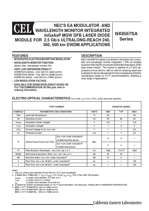
NEC's NX8567SA Series is an Electro-Absorption (EA) modu-lator and wavelength monitor integrated, 1 550 nm MultipleQuantum Well (MQW) structured Distributed Feed-Back (DFB) laser diode module. The module is capable of 2.5 Gb/s ap-plications of over 240 km, 360 km, 600 km ultralong-reach and available for Dense Wavelength Division Multiplexing (DWDM) wavelengths based on ITU-T recommendations, enabling a wide range of applicationsDESCRIPTION• INTEGRATED ELECTROABSORPTION MODULATOR • WAVELENGTH MONITOR FUNCTION(Etalon Þ lter, Wavelength monitor PD)• VERY LOW DISPERSION PENALTYNX8567SAS Series - over 240 km (4320 ps/nm) NX8567SAM Series - over 360 km (6480 ps/nm) NX8567SA Series - over 600 km (10800 ps/nm)• LOW MODULATION VOLTAGE• AVAILABLE FOR DWDM WAVELENGHT BASED ON ITU-T RECOMMENDATION (50 GHz grid, refer to ordering information)FEATURESCalifornia Eastern LaboratoriesPART NUMBERNX8567SA SERIESSYMBOLS PARAMETERS AND CONDITIONSUNITS MIN TYPMAX T SET Laser Set Temperature 1°C 2035I OP Operating CurrentmA 506080V center Modulation Center Voltage 2V -2.0–-0.5V mod Modulation Voltage 2V –23V FLD For w ard Voltage of LD, I FLD = I OP V –– 2.0I THThresh o ld CurrentmA–720P fOptical Output Power from Fiber,I FLD = I OP , Under modulation 2(NX8567SAM/SA Series)dBm-5-2–I FLD = I OP , Under modulation 2(NX8567SAS Series)0+1–λP Peak Emission Wavelength, I FLD = I OP , V EA = 0 V nm 1528 ITU-T 31564SMSR Side Mode Suppression Ratio, I FLD = I OP , V EA = 0 V dB 3040–ER Extinction Ratio, I FLD = I OP , Under modulation 2dB 1011–t f Rise Time, I FLD = I OP , 20-80%, Under modulation 2ps ––125t rRise Time, I FLD = I OP , 80-20%, Under modulation 2ps ––125ELECTRO-OPTICAL CHARACTERISTICS (T LD = Tset, T C = -5 to +70°C, unless otherwise speci Þ ed)Notes:1. Tset is a certain point between 20 and 35C for ITU-T grid wavelength2. 2.48832 Gb/s, PRBS 223 -1, V EA = V center ±1/2 Vmod, I FLD = I op , TLD = Tset, NEC Test System V center : a certain point between -2.0 and -0.5 V V mod : a certain point 3 V or below I op : a certain point between 50 and 80 mA3. Available for DWDM wavelenght based on ITU-T recommendation (100 GHz grid). Please refer to ORDERING INFORMATION.4. BER = 10-10, NX8567SAS: 240 km (4320 ps/nm) BER = 10-10, NX8567SAM: 360 km (6480 ps/nm) BER = 10-10, NX8567SA: 600 km (10800 ps/nm)NX8567SA SERIESELECTRO-OPTICAL CHARACTERISTICS (T LD = Tset, T C = -5 to +70°C, Unless otherwise speci Þ ed)PART NUMBERNX8567SA SERIESSYMBOLSPARAMETERS AND CONDITIONSUNITS MIN TYP MAX DPDispension Penalty, I FLD = I op , SMF Under modulation 2,4dB––2I S IsolationdB 23––S 11Input Return LossI FLD = I op , V EA = -1 V, 50 Ω130 MHz to 2 GHzdB––-8 I FLD = I op , V EA = -1 V, 50 Ω 2 GHz to 2.5 GHz––-5Notes:1. Tset is a certain point between 20 and 35C for ITU-T grid wavelength2. 2.48832 Gb/s, PRBS 223 -1, V EA = V center ±1/2 Vmod, I FLD = I op , TLD = Tset, NEC Test System V center : a certain point between -2.0 and -0.5 V V mod : a certain point 3 V or below I op : a certain point between 50 and 80 mA3. Available for DWDM wavelenght based on ITU-T recommendation (100 GHz grid). Please refer to ORDERING INFORMATION.4. BER = 10-10, NX8567SAS: 240 km(4320 ps/nm) BER = 10-10, NX8567SAM: 360 km (6480 ps/nm) BER = 10-10, NX8567SA: 600 km (10800 ps/nm)ELECTRO-OPTICAL CHARACTERISTICS (Applicable to Monitor PD, T LD = Tset, T C = -5 to +70°C, BOL)SYMBOLS PARAMETERS AND CONDITIONSUNITS MIN TYP MAX I m (Pf)Monitor Current (P f Monitor), V RPD = 5 V, I FLD = I opµA 10–200I m (λp)Monitor Current (λp Monitor), V RPD = 5 V, I FLD = I op , Locking point µA 5–100I m (λ)Operation Region%25–75|λ1-λ2|pm 90––ηλDiscrimination Slope 1, V RPD = 5 V, I FLD = I op , Locking point µA/pm 0.24––I D Dark Current, V RPD = 5 V, V EA = 0 VnA ––10C t Terminal Capacitance, V RPD = 5 V, f = 1 MHz pF ––15γ2Tracking Error, I m (Pf) = const.dB––0.5Note:1. Operating region, Discrimination slope, Slope assignmentI I m I m (λp I m I 1: I m I 2: Im Negative SlopeI m I m I m (λp I m I 2: I m I 1: I m (nm)Positive Slopeµmmset , T C = 25ûC, T C = –20 to +70ûCP P fγ = 10 log[dB]P f P op2. Tracking error: γNote:1.Operation in excess of any one of these parameters may result in permanent damage.ABSOLUTE MAXIMUM RATINGS 1SYMBOLSPARAMETERSUNITS RATINGSP f Optical Output Power from Fiber mW 10I FLD Forward Current of LD mA 150V RLD Reverse Voltage of LD V 2.0V Fm Forward Voltage of Modulator V 1V Rm Reverse Voltage of Modulator V 5I FPD Forward Current of PD mA 1V RPD Reverse Voltage of PD V 10I C Cooler Current A 1.5V C Cooler VoltageV 2.5T C Operating Case Temperature °C -5 to +70T STG Storage Temperature °C -40 to +85T SLDLead Soldering Temp. (3 s)°C350NX8567SA SERIESELECTRO-OPTICAL CHARACTERISTICS (Applicable to Thermistor and TEC, T C = -5 to +70°C)PART NUMBERNX8567SA SERIESSYMBOLS PARAMETERS AND CONDITIONSUNITSMINTYP MAX R Thermistor Resistance, T LD = 25°Ck Ω9.510.010.5B B ConstantK 335034503550I C Cooler Current, T LD = T set A 1.2V CCooler Voltage, T LD = T setV2.4ORDERING INFORMATION NX8567SA SERIES Wavelength CodeITU-T Wavelength *1(nm)Frequency (THz)Wavelength CodeITU-T Wavelength *1(nm)Frequency (THz)2871528.773196.104571545.720193.952911529.163196.054611546.119193.902951529.553196.004651546.518193.852991529.553195.954691546.917193.803031530.334195.904731547.316193.703071530.725195.854771547.715193.703111531.116195.804851548.515193.603151531.507195.754891548.915193.553181531.898195.704931549.315193.503221532.290195.654971549.715193.453261532.681195.605011550.116193.403301533.073195.555051550.517193.353341533.465195.505091550.918193.303381533.073195.455131551.319193.253421534.250195.405171551.721193.203461534.643195.355211552.122193.153501535.036195.305251552.524193.103541535.429195.255291552.926193.053581535.822195.205331553.329193.003621536.216195.155371553.731192.953661536.643195.105411554.134192.903701537.003195.055451554.537192.853731537.397195.005491554.940192.803771537.792194.955531555.343192.753811538.186194.905571555.747192.703851538.581194.855611556.151192.653891538.976194.805651556.555192.603931539.371194.755691556.959192.553971539.766194.705731557.363192.504011540.162194.655771557.768192.454051540.557194.605811558.173192.404091540.953194.555851558.578192.304131541.349194.505891558.983192.304171541.746194.455931559.389192.254211542.142194.405971559.794192.204251542.539194.356021560.200192.154291542.936194.306061560.606192.104331543.333194.256101561.013192.054371543.730194.206141561.419192.004411544.128194.156181561.826191.954451544.526194.106221562.233191.904491544.924194.056261562.640191.854531545.322194.006301563.047191.80TABLE A: DWDM wavelengths based on ITU-T recommendations (@ TLD = Tset)Note:1. λ monitor slope: Channel frequency for 191.80 THz + 2n × 0.05 THz is assigned on negative slope. Channel frequency for 191.80 THz + (2n + 1) × 0.05 THz is assigned on positive slope. n is a positive integer including zero.NX8567SA-CC : SC-UPC connector (standard) BC : FC-UPC connector (option)Wavelength code : Refer to Table A Without : 600 km (10800 ps/nm) M : 360 km (6480 ps/nm) S : 240 km (4320 ps/nm)OUTLINE DIMENSIONS (Units in mm)OPTICAL FIBER CHARACTERISTICSPARAMETERUNITS SPECIFICATIONMode Field Diameter µm 9.3±0.5Cladding Diameter µm 125±1Tight Buffer Diameter µm 900±100Cut-off Wavelenghtnm < 1270Attenuation 1525 to 1575 nm dB/km < 0.3Minimum Fiber Bending Radius mm 30Fiber Length mm1225 MINFlammabilityUL1581VW-107/29/2003Life Support ApplicationsThese NEC products are not intended for use in life support devices, appliances, or systems where the malfunction of these products can reasonably be expected to result in personal injury. The customers of CEL using or selling these products for use in such applications do so at their own risk and agree to fully indemnify CEL for all damages resulting from such improper use or sale.NX8567SA SERIES8.99±0.5 m m。
muisc

主变短路阻抗和负载损耗测量(75℃)主变空载损耗和空载电流测量:有载开关型号:CVⅢ-350Y/63-10193W;生产厂家:上海华明电力设备制造有限公司主变短路阻抗和负载损耗测量(75℃)主变空载损耗和空载电流测量:有载开关型号:CVⅢ-350Y/63-10193W;生产厂家:上海华明电力设备制造有限公司4.2 额定运行方式4.2.1变压器在额定使用条件下,全年可按额定容量运行。
4.2.2变压器的外加一次电压可以较额定一次电压为高,但一般不得超过相应分接头电压的5%。
4.2.3运行中的变压器在环境温度40℃时,其温升不得超过55℃,既最高上层油温不超过95℃,一般不宜经常超过85℃。
温升=上层油温 - 环境温度4.2.4变压器三相负荷不平衡时,应注意监视最大负荷相的电流值。
4.3允许的过负荷运行4.3.1变压器可以在正常过负荷和事故过负荷的情况下运行。
正常过负荷可以经常使用,但不能长期过负荷运行,其允许值根据变压器的负荷曲线、冷却介质温度以及过负荷前变压器所带的负荷等来确定。
变压器存在较大的缺陷(例如冷却系统不正常,严重漏油,色谱分析异常等)时不准过负荷运行。
当发现过负荷时,要立即汇报调度,并将过负荷的大小和持续时间记入运行工作记录簿和设备档案中。
4.3.24.4变压器的监视与维护4.4.1值班人员在投运变压器之前,应仔细检查,并确认管道阀门开闭正确、变压器在完好状态,具备带电运行条件。
对长期停用或检修后的变压器应检查接地线等是否已拆除,核对分接开关位置和测量绝缘电阻等有关试验,并将测得的数据记入变压器档案。
4.4.2变压器应长期进行外部检查,检查的周期与值班巡视周期相同。
在气候激变时(冷、热)应对变压器的油面进行额外的检查。
瓦斯继电器发出信号时,应进行外部检查。
雷雨后,应检查有无放电现象,避雷器及保护的动作情况。
4.4.3变压器定期外部检查的一般项目:a.储油柜和充油套管的油位、油色均应正常,且不渗漏油;b.套管外部应清洁、无破损裂纹、无放电痕迹及其它异常现象;c.变压器音响正常、本体无渗油、漏油,吸湿器应完好,硅胶应有效,呼吸应畅通;d.运行中的各冷却器温度应相近,油温正常,管道阀门开闭正确,散热器上下管道温差大于5℃;e.引线接头、电缆应无发热征象;f.瓦斯继电器内应无气体,继电器与储油柜间连接阀门应打开;4.5瓦斯保护装置的运行4.5.1变压器运行时主变本体的轻瓦斯保护投信号重瓦斯保护应投跳闸。
冷却塔性能参数说明.
1.设备组成1.1设备原产地及制造厂家广东省广州市/斯必克(广州)冷却技术有限公司。
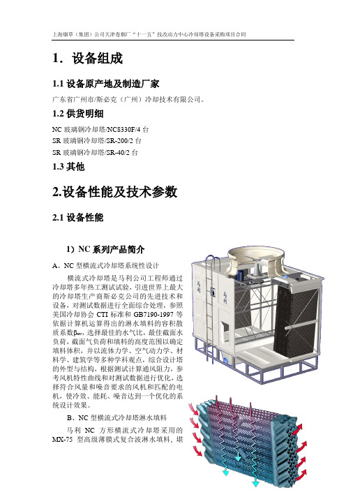
1.2供货明细NC玻璃钢冷却塔/NC8330F/4台SR玻璃钢冷却塔/SR-200/2台SR玻璃钢冷却塔/SR-40/2台1.3其他2.设备性能及技术参数2.1设备性能1)NC系列产品简介A、NC型横流式冷却塔系统性设计横流式冷却塔是马利公司工程师通过冷却塔多年热工测试试验,引进世界上最大的冷却塔生产商斯必克公司的先进技术和设备,对测试数据进行全面综合处理,参照美国冷却协会CTI标准和GB7190-1997等依据计算机运算得出的淋水填料的容积散质系数 xv,选择最佳的水气比,最佳截面水负荷,截面气负荷和填料的高度范围以确定填料体积,并以流体力学、空气动力学、材料学、建筑学等多种学科观点,综合设计塔的外型与结构,根据测试计算通风阻力,参考风机特性曲线和对测试数据进行优化,选择符合风量和噪音要求的风机和匹配的电机,使冷效、能耗、噪音达到一个优化的系统设计效果。
B、NC型横流式冷却塔淋水填料马利NC方形横流式冷却塔采用的MX-75型高级薄膜式复合波淋水填料, 堪称世界上薄膜式淋水填料的佼佼者,此填料片用于横流冷却塔, 由热处理PVC多层片构成,厚度0.38mm, 表面成波纹式, 相邻两层填料片形成的间隔,保证气流的通畅,经美国冷却塔协会(CTI)测试分析,其阻力特性和热力特性远远优于现有国内填料,使用寿命15年以上。
一般冷却塔产品填料均采用竖直放置,且无明显收水端。
参考右下图,一般冷却塔的做法是布水盘偏向外侧安装,A、B、C、D、E、F这6个区域内充满了填料,而当冷却塔运行起来以后,由于风机向上排风,气流由外向内流经填料,在风力的带动下,实际冷却水流过的区域是C、D、E、F、G这5个区域,A、B两区无水。
那么按照一般冷却塔的做法,用,而有水的G区却又没有填料。
马利的工程师们对这个问题进行了深入的研究,在千百次的实验之后,提出了冷却塔填料倾斜悬挂式安装的方案,在马利冷却塔当中C、D、E、F、G区充满填料,A、B两区无填料,而倾斜的角度又根据不同的塔型有十分严格的要求,这种方法有效地解决了进风面下端“无水区”问题,且填料带有明显的收水端,克服了竖直放置填料的缺点。
NX-700中文说明书
航行告警接收机NX-700A/B操作说明书* * * * * * * * * * * * * * * * * * * * * * * * * * * * * * *确认键指针键进入/推出菜单键开启LIST 选项 开启打印选项开/关键版本号按键说明一、 开机/关机按 键开机,显示器会发出“必”声,显示器会显示开机屏,如下图:1、ROM 、RAM 操作检查OK ,会显示:2、如检查到错误操作,所有的信息都在518KHz 下显示,如下:亮度调节按选择518KHz或490KHz.按关机。
二、 调节亮度按调整亮度,0(全黑)至9(最亮),+ 增加,- 减少。
三、 确认新信息SAR(搜救)信息1、当接收到一个SAR信息时,回显示信息内容及响报警。
SAR 信息图标2、按开关键以外的任意键静音。
其他信息1、收到SAR信息以外的信息,显示如下其中之一:国际信息本地信息2、如直接读取,按键选择“YES”然后按ENT键;3、如想以后再读取,选择“NO”,然后按ENT键关闭窗口。
四、 信息例子按选择键上的选择一个信息,然后按ENT键显示信息内容。
按ENT键在信息清单和信息明细之间转换。
注意:1、显示屏下方的操作指南显示当前显示下可用的按键;2、字体大小可调整,详细见。
按键显示模式功能清单滚动清单详细滚动信息清单转换国际及本地信息详细显示最新()及之前()的信息清单显示主菜单MENU详细清单显示所选择的信息明细ENT详细显示信息清单清单显示菜单选项LIST详细清单显示打印选项PRINT详细五、 选择接收模式有自动及手动两种接收模式选择:AUTO MODE(自动模式)要求航行数据,接收机会根据本船与NA VTEX地面站之间的距离选择。
如果没有输入航行数据,会选择所有的地面站。
ISN模式允许选择模式1、按MUNE/ESC 键,进入主菜单;2、按选择 NA VTEX。
3、按ENT键或键打开NA VTEX菜单;4、按选择接收模式,然后按ENT键或显示所选择的接收模式。
海德汉光栅尺技术参数(用于NC数控机床)(HEIDENHAIN)
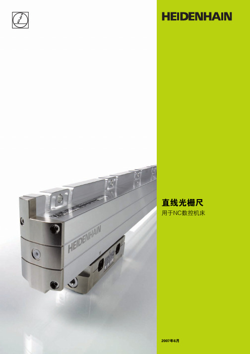
用于NC数控机床
2007年6月
更多信息,请访问 或来函索取。
产品样本: • 敞开式直线光栅尺 • 内置轴承角度编码器 • 无内置轴承角度编码器 • 旋转编码器 • HEIDENHAIN后续电子设备 • HEIDENHAIN数控系统 • 机床检测和验收测试测量系统
扫描单元
密封条
安装板
LC 183封闭式直线光栅尺结构示意图
DIADUR 光栅尺
光源
光电池
5
选型指南
纤细外壳的直线光栅尺
纤细外壳的直线光栅尺主要用于安装空间 有限的地方。如果使用安装板或固定元件, 可实现较大测量范围和支持更高加速度 载荷。
绝对式直线光栅尺 • 玻璃光栅尺
高重复性增量式 直线光栅尺 • 钢光栅尺 • 信号周期小
光栅尺栅距越小,光电扫描的衍射现象越严 重。HEIDENHAIN公司的直线光栅尺采用两 种扫描原理:
• 成像扫描原理,用于20 µm和40 µm栅距 光栅尺。
• 干涉扫描原理,用于栅距8 µm甚至更小 光栅。
成像扫描原理 简单的说,成像扫描原理是采用透射光生成 信号:栅距相同或相近的光栅尺和扫描光栅 彼此相对运动。扫描光栅的基体是透明的, 而作为测量基准的光栅尺可以是透明的也 可以是反射的。
带距离编码参考点光栅尺或编码器,其绝对 参考点位置通过累计两个参考点间信号周 期数并用以下公式计算:
P1 = (abs B-sgn B-1) x
N 2
+ (sgn B-sgn
D) x
abs MRR 2
其中: B = 2 x MRR-N
和:
N
P1 = 信号周期中代表移过第一个参考点
的位置
D
abs = 绝对值
RQA0008NXAQS中文资料

RQA0008NXAQSSilicon N-Channel MOS FETREJ03G1569-0100Rev.1.00Jul 04, 2007Features• High Output Power, High Gain, High EfficiencyPout = +36 dBm, Linear Gain = 18 dB, PAE = 65% (f = 520 MHz)• Compact package capable of surface mountingOutline*UPAK is a trademark of Renesas Technology Corp.Absolute Maximum Ratings(Ta = 25°C)UnitRatingsItem SymbolDrain to source voltage V DSS 16 V Gate to source voltage V GSS ±5 V Drain current I D 2.4 A Channel dissipation Pch note 10 W Channel temperature Tch 150 °CStorage temperature Tstg –55 to +150 °CNote: Value at Tc = 25°CThis device is sensitive to electro static discharge. An adequate careful handling procedure is requested.Electrical Characteristics(Ta = 25°C)Item Symbol Min. Typ Max. Unit Test ConditionsZero gate voltage drain current I DSS — — 10 µA V DS = 16 V, V GS = 0 Gate to source leak current I GSS — — ±2 µA V GS = ±5 V, V DS = 0 Gate to source cutoff voltage V GS(off) 0.15 0.4 0.8 V V DS = 6 V, I D = 1 mA Forward Transfer Admittance |yfs| — 2.4 — S V DS = 6 V, I D = 1.2 A Input capacitance Ciss — 44 — pF V GS = 5 V, V DS = 0, f = 1 MHz Output capacitance Coss — 25 — pF V DS = 6 V, V GS = 0, f = 1 MHz Reverse transfer capacitance Crss — 6.0 — pF V DG = 6 V, V GS = 0, f = 1 MHz — 36 — dBm Output Power Pout — 3.98 — WPower Added Efficiency PAE — 65 — % V DS = 6 V, I DQ = 400 mAf = 520 MHz, Pin = +20 dBmMain CharacteristicsEvaluation Circuit (f = 520 MHz)S Parameter(V DS = 6 V, I DQ = 400 mA, Zo = 50 Ω)S11 S21 S12 S22(deg.) MAG ANG(deg.)(deg.)MAG ANGf(MHz) MAG ANG(deg.) MAG ANG100 0.883 -170.0 8.48 84.9 0.021 -3.0 0.867 -175.4 150 0.904 -175.7 5.46 80.1 0.021 -5.3 0.879 -177.3 200 0.902 -178.2 4.13 72.6 0.021 -12.0 0.872 -178.5 250 0.900 179.6 3.30 67.1 0.021 -16.5 0.872 -179.7 300 0.898 177.8 2.75 61.6 0.021 -19.8 0.873 179.5 350 0.898 176.2 2.34 56.2 0.020 -24.2 0.873 178.8 400 0.897 174.8 2.04 50.9 0.020 -27.7 0.874 178.4 450 0.898 173.4 1.80 45.7 0.020 -31.3 0.873 177.8 500 0.899 172.3 1.61 40.7 0.020 -34.4 0.873 177.4 550 0.900 171.2 1.46 35.5 0.019 -38.2 0.875 176.8 600 0.900 170.1 1.33 30.5 0.019 -41.5 0.876 176.5 650 0.899 169.0 1.22 25.5 0.019 -45.0 0.876 176.0 700 0.899 167.9 1.13 20.5 0.019 -47.8 0.878 175.6 750 0.899 166.9 1.04 15.6 0.018 -51.2 0.878 175.2 800 0.898 165.8 0.97 10.6 0.018 -54.8 0.880 174.9 850 0.899 164.7 0.91 5.7 0.018 -57.4 0.878 174.4 900 0.901 163.7 0.85 0.9 0.018 -60.9 0.880 173.9 950 0.903 162.7 0.80 -3.9 0.017 -63.5 0.882 173.5 1000 0.903 161.8 0.75 -8.7 0.017 -66.5 0.883 173.1 1050 0.903 160.8 0.71 -13.4 0.017 -69.3 0.884 172.6 1100 0.905 159.8 0.68 -18.1 0.016 -71.9 0.883 172.1 1150 0.906 158.8 0.64 -22.8 0.016 -74.8 0.886 171.6 1200 0.907 157.8 0.61 -27.3 0.016 -76.8 0.888 171.2 1250 0.909 156.8 0.58 -32.0 0.015 -79.6 0.891 170.8 1300 0.911 155.8 0.55 -36.6 0.015 -81.9 0.893 170.4 1350 0.912 154.9 0.52 -41.2 0.015 -84.1 0.896 170.0 1400 0.912 154.0 0.50 -45.8 0.015 -86.2 0.897 169.5 1450 0.912 153.1 0.48 -50.3 0.014 -88.6 0.898 169.1 1500 0.913 152.1 0.46 -54.8 0.014 -90.2 0.900 168.7 1550 0.914 151.2 0.44 -59.2 0.014 -92.6 0.900 168.4 1600 0.915 150.3 0.42 -63.8 0.014 -94.1 0.902 167.8 1650 0.916 149.4 0.40 -68.3 0.013 -95.9 0.903 167.4 1700 0.915 148.5 0.39 -72.6 0.013 -97.6 0.904 167.0 1750 0.914 147.6 0.38 -76.9 0.013 -99.0 0.904 166.4 1800 0.913 146.7 0.36 -81.1 0.013 -100.8 0.906 165.8 1850 0.915 145.7 0.35 -85.3 0.013 -102.2 0.909 165.5 1900 0.920 144.5 0.34 -89.5 0.013 -103.9 0.909 165.0 1950 0.923 143.3 0.33 -93.6 0.013 -105.8 0.910 164.5 2000 0.925 142.3 0.31 -97.9 0.013 -107.2 0.911 163.9 2050 0.926 141.4 0.30 -102.1 0.013 -108.7 0.913 163.5 2100 0.928 140.5 0.29 -106.3 0.013 -109.9 0.914 163.0 2150 0.929 139.6 0.28 -110.6 0.013 -112.2 0.916 162.4 2200 0.930 138.7 0.27 -114.7 0.013 -112.8 0.917 161.8 2250 0.932 137.8 0.27 -118.9 0.013 -114.9 0.921 161.5 2300 0.931 137.1 0.26 -123.0 0.013 -116.5 0.921 161.0 2350 0.930 136.3 0.25 -127.1 0.013 -118.5 0.921 160.5 2400 0.926 135.5 0.24 -131.2 0.013 -120.2 0.924 159.9 2450 0.922 134.4 0.24 -135.4 0.014 -121.9 0.923 159.5 2500 0.920 133.3 0.23 -139.5 0.014 -123.7 0.921 159.0Package DimensionsOrdering InformationPart Name Quantity Shipping Containerφ178 mm reel, 12 mm emboss tapingRQA0008NXTL-E 1000pcs.Note: For some grades, production may be terminated. Please contact the Renesas sales office to check the state of production before ordering the product.Refer to "/en/network " for the latest and detailed information.Renesas Technology America, Inc.450 Holger Way, San Jose, CA 95134-1368, U.S.A Tel: <1> (408) 382-7500, Fax: <1> (408) 382-7501Renesas Technology Europe LimitedDukes Meadow, Millboard Road, Bourne End, Buckinghamshire, SL8 5FH, U.K.Tel: <44> (1628) 585-100, Fax: <44> (1628) 585-900Renesas Technology (Shanghai) Co., Ltd.Unit 204, 205, AZIACenter, No.1233 Lujiazui Ring Rd, Pudong District, Shanghai, China 200120Tel: <86> (21) 5877-1818, Fax: <86> (21) 6887-7898Renesas Technology Hong Kong Ltd.7th Floor, North Tower, World Finance Centre, Harbour City, 1 Canton Road, Tsimshatsui, Kowloon, Hong Kong Tel: <852> 2265-6688, Fax: <852> 2730-6071Renesas Technology Taiwan Co., Ltd.10th Floor, No.99, Fushing North Road, Taipei, Taiwan Tel: <886> (2) 2715-2888, Fax: <886> (2) 2713-2999Renesas Technology Singapore Pte. Ltd.1 Harbour Front Avenue, #06-10, Keppel Bay Tower, Singapore 098632 Tel: <65> 6213-0200, Fax: <65> 6278-8001Renesas Technology Korea Co., Ltd.Kukje Center Bldg. 18th Fl., 191, 2-ka, Hangang-ro, Yongsan-ku, Seoul 140-702, Korea Tel: <82> (2) 796-3115, Fax: <82> (2) 796-2145Renesas Technology Malaysia Sdn. BhdUnit 906, Block B, Menara Amcorp, Amcorp Trade Centre, No.18, Jalan Persiaran Barat, 46050 Petaling Jaya, Selangor Darul Ehsan, Malaysia Tel: <603> 7955-9390, Fax: <603> 7955-9510RENESAS SALES OFFICES。
上海施耐德日盛双螺杆压缩机操作维修手册

目录1.0产品介绍 (3)2.0安全 (4)2.1总则 (4)2.2个人防护设备 (4)2.3压力 (4)2.4防火、防爆 (4)2.5移动及旋转机械的保护 (4)2.6危险表面 (5)2.7有害物质 (5)2.8起吊和运输 (5)2.9防止人员关闭在机器内 (5)2.10操作 (5)3.0总体描述 (5)3.1操作原理 (6)3.2控制系统 (6)3.3进气温度 (7)3.3.1 冷凝--低温 (7)3.3.2 过热--高温 (7)3.3.3 排气温度 (7)4.0 技术特性 (8)4.1 电器特性 (8)4.2润滑油特性 (8)4.2.1 电动机轴承用油 (8)5.0 安装和开机前检查 (9)5.1 位置要求 (9)5.2 散热要求 (9)5.3 对水冷却型机组,冷却水质的要求 (10)5.4 空气管道系统的连接要求 (10)5.5 电器安装要求及电器检查 (11)5.5.1 电源 (11)5.5.2 电机转向 (11)5.6机械检验 (11)5.6.1螺杆机头检查 (11)5.6.2油位检查 (12)5.6.3传动系统的检查 (12)5.6.4检查系统里所有的阀门 (12)6.0 操作 (12)6.1 开机前的准备 (12)6.2 初始开机程序 (13)6.2.1 日常开机程序 (13)6.2.2 停机程序 (13)6.3 功能控制 (14)6.3.1 标准型 (14)6.3.2智能型操作使用介绍 (14)6.4 压力开关控制 (15)6.5 高温停机 (15)6.5.1螺杆机头的高温保护 (15)6.6 电机热过载保护 (15)6.7 温控阀 (15)7.0 选项 (16)7.1 主、备机控制方式 (16)7.2 油过滤器压差显示 (16)7.3 空气过滤器压差显示 (16)7.4 油气分离筒压差显示 (16)7.5 遥控启动/停止装置 (16)7.6 加载定时器 (17)8.0 保养 (17)8.1 总则 (17)8.2日常操作 (17)8.2.1 保养计划 (17)8.2.2 运行500小时 (18)8.2.3 每3000小时 (18)8.2.4 每6000小时 (18)8.3 保养指导 (18)8.3.1 空气过滤器的保养方法 (19)8.3.2 油过滤器的保养方法 (19)8.3.3 油气分离器的保养方法 (19)8.3.4 进气控制阀的特性及保养方法 (19)8.3.5 最小压力控制阀的保养方法 (20)8.3.6 润滑油的更换方法 (20)8.3.7 油位 (20)8.3.8 皮带松紧度的调整方法 (20)8.3.9 更换皮带方法 (21)8.3.11膜片联轴器的对中 (21)8.3.12 电动机的保养方法 (21)8.4 故障排除表 (22)附页:智能型控制系统 (23)标准型电气原理图1.0产品介绍施耐德日盛螺杆式空气压缩机结构设计独特,具有结构紧凑、外型别致、效率高、能耗小、噪音低和使用寿命长等特点,属智能环保型产品。
NX8571SC741-BA中文资料
元器件交易网
NX8571 Series
8.2±0.2 5.4
0.3 1.0
PACKAGE DIMENSIONS (UNIT: mm)
8.89±0.13 10 MIN. 1.25
15.24 2.54
7
1
21.8±0.3 1.0 0.8
φ 0.9
8
14
0.5 20.83±0.25 26.04±0.25
monitor, E.O.L
∆ν Pf = 10 mW, CW, 3 dB down
SMSR Pf = 10 mW, CW
RIN Pf = 10 mW, 20 MHz to 3 GHz
Is
Pf = 10 mW, CW
ext Pf = 10 mW, CW
MIN. TYP. MAX. Unit
20
35
°C
1530.33 1530.72 1531.11 1531.50 1531.89 1532.29 1532.68 1533.07 1533.46 1533.85 1534.25 1534.64 1535.03 1535.42 1535.82 1536.21 1536.60 1537.00 1537.39 1537.79 1538.18 1538.58 1538.97 1539.37
Positive Slope (Even channel)
*2 Tracking Error: γ
Pf (mW)
TLD = Tset
10
TLD = Tset, TC = –5 to +70˚C
Pf
γ = 10 log Pf [dB]
10
0
Im
Im
ELECTRO-OPTICAL CHARACTERISTICS (Applicable to Thermistor and TEC: TLD = Tset, TC = −5 to +70°C)
- 1、下载文档前请自行甄别文档内容的完整性,平台不提供额外的编辑、内容补充、找答案等附加服务。
- 2、"仅部分预览"的文档,不可在线预览部分如存在完整性等问题,可反馈申请退款(可完整预览的文档不适用该条件!)。
- 3、如文档侵犯您的权益,请联系客服反馈,我们会尽快为您处理(人工客服工作时间:9:00-18:30)。
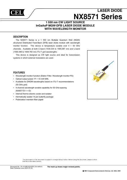
LASER DIODENX8571 Series1 550 nm CW LIGHT SOURCEInGaAsP MQW-DFB LASER DIODE MODULEWITH WAVELENGTH MONITORDESCRIPTIONThe NX8571 Series is a 1 550 nm Multiple Quantum Well (MQW) structured Distributed Feed-Back (DFB) laser diode module with wavelength monitor function. This device is temperature tunable over 4 × 50 GHz channels. Available at both C-band (1530.334 to 1565.087 nm) and L-band (1565.496 to 1608.760 nm) ITU-T grid wavelengths.This device is designed as CW light source and ideal for transmission systems in which external modulators are used.FEATURES• Wavelength monitor function (Etalon Filter, Wavelength monitor PD) • Optical output power: P f = 10 mW MIN.• Available for DWDM wavelengths based on ITU-T recommendations (50 GHz grid)• 4-channel wavelength tunable capability for 50 GHz-spacing (NX8571S ××××D)• Internal thermo-electric cooler and isolator • Hermetically sealed 14-pin butterfly package • Polarization maintain fiber pigtailDocument No. PL10136EJ03V0DS (3rd edition) Date Published June 2004 CP (K)© NEC Compound Semiconductor Devices, Ltd. 2002, 2004The mark shows major revised points.PACKAGE DIMENSIONS (UNIT: mm)OPTICAL FIBER CHARACTERISTICSParameter Specification UnitOuter Diameter0.9±0.1 mm Minimum Fiber Bending Radius 25 mm Fiber Length1 000 MIN.mmData Sheet PL10136EJ03V0DS2ABSOLUTE MAXIMUM RATINGSRatings UnitParameter SymbolForward Current of LD I F 300 mAReverse Voltage of LD V R 2.0 VForward Current of PD I F 10 mAReverse Voltage of PD V R 20 VOperating Case Temperature T C−20 to +70 °CStorage Temperature T stg−40 to +85 °CLead Soldering Temperature T sld260 (10 sec.) °CELECTRO-OPTICAL CHARACTERISTICS (T LD = T set, T C = −5 to +70°C, unless otherwise specified)MAX.UnitTYP.Parameter Symbol Conditions MIN.channel 20 35 °CLaser Set Temperature T set Single4 channel tunable 10 45Forward Voltage V F P f = 10 mW 0.9 1.2 2.5 VThreshold Current I th20 40 mAOperation Current I op P f = 10 mW 70 125 mAOptical Output Power from Fiber P f I F = 125 mA, T LD = T set 10 mWITU-T *1 1 609 nm530Peak Emission Wavelength λp P f = 10 mW, CW, T LD = T set 1−20 +20 pm Wevelength Stability −T LD = T set, applicable to wavelengthmonitor, E.O.LSpectral Line Width ∆νP f = 10 mW, CW, 3 dB down 1 2 MHzSide Mode Suppression Ratio SMSR P f = 10 mW, CW 35 45 dBRelative Intensity Noise RIN P f = 10 mW, 20 MHz to 3 GHz −150 dB/HzOptical Isolation I s P f = 10 mW, CW 30 dBPolarization Extinction Ratio *2ext P f = 10 mW, CW 20 dB*1Available for DWDM wavelengths based on ITU-T recommendations (50 GHz grid).Please refer to Table A.*2 Polarization state of LD is aligned parallel to the slow axis.Data Sheet PL10136EJ03V0DS 3ELECTRO-OPTICAL CHARACTERISTICS (Applicable to Monitor PD: T LD = T set , T C = −5 to +70°C)Parameter Symbol Conditions MIN. TYP. MAX. UnitMonitor Current (P f Monitor) I m (P f ) P f = 10 mW, V R = 5 V20 200 µA Monitor Current (λp Monitor) I m (λp ) P f = 10 mW, V R = 5 V, Locking point 10100µAOperation Region *1I m (λ)25 75%⏐λ1−λ2⏐ 90pm Discrimination Slope *1ηλ0.05µA/pm Dark Current I D V R = 5 V 2 10 nA Tracking Errorγ*2I m = const.0.5dB*1 Operation region, Discrimination slope, Slope assignmentI I m I m (λp I m I 1: I m I 2: I m Negative Slope (Odd channel)I m (λ)I m I m (λp I m I 2: I m I 1: I m λPositive Slope (Even channel)µ*2 Tracking Error: γmmset, T C = –5 to +70˚C10P fγ = 10 log[dB]P f 10ELECTRO-OPTICAL CHARACTERISTICS(Applicable to Thermistor and TEC: T LD = T set , T C = −5 to +70°C)Parameter Symbol Conditions MIN. TYP. MAX. UnitThermistor Resistance R T LD = 25°C 9.5 10.0 10.5 k Ω B Constant B T LD = 25°C3 350 3 450 3 550 K Cooler Current I C ∆T = 70 − T set , P f = 10 mW 1.5 A Cooler VoltageV C∆T = 70 − T set , P f = 10 mW3.0VData Sheet PL10136EJ03V0DS4ORDERING INFORMATIONNX8571SC -BAWith FC-PC connector Without : Single channel D : 4 channel tunable Wavelength code : Refer to Table A Package codeTable A: DWDM wavelength base on ITU-T recommendations (@ T LD = T set ) (1/7)Wavelength CodeITU-T Wavelength*1Frequency Monitor Slope 4 channel tunablesingle channel (nm)(THz)315D 303 1530.33 195.90 Negative 307 1530.72 195.85 Positive 311 1531.11 195.80 Negative 315 1531.50 195.75 Positive 330D 318 1531.89 195.70 Negative 322 1532.29 195.65 Positive 326 1532.68 195.60 Negative 330 1533.07 195.55 Positive 346D 334 1533.46 195.50 Negative 338 1533.85 195.45 Positive 342 1534.25 195.40 Negative 346 1534.64 195.35 Positive 362D 350 1535.03 195.30 Negative 354 1535.42 195.25 Positive 358 1535.82 195.20 Negative 362 1536.21 195.15 Positive 377D 366 1536.60 195.10 Negative 370 1537.00 195.05 Positive 373 1537.39 195.00 Negative 377 1537.79 194.95 Positive 393D 381 1538.18 194.90 Negative 385 1538.58 194.85 Positive 389 1538.97 194.80 Negative 393 1539.37 194.75 Positive*1 The value which omitted and computed the 3rd place below the decimal pointData Sheet PL10136EJ03V0DS5Table A: DWDM wavelength base on ITU-T recommendations (@ T LD = T set) (2/7)Slope Wavelength Code ITU-T Wavelength *1Frequency Monitor4 channel tunable single channel (nm) (THz)Negative194.70 409D 397 1539.76Positive194.65 4011540.16Negative194.601540.55405Positive194.551540.95409Negative194.50 425D 413 1541.34Positive194.451541.74417194.40Negative1542.14421Positive194.351542.53425Negative 441D 429 1542.93194.30Positive194.251543.33433194.20Negative1543.73437Positive194.151544.12441194.10Negative 457D 445 1544.52194.05Positive1544.92449194.00Negative1545.32453Positive193.951545.72457Negative193.90 473D 461 1546.11Positive193.851546.51465Negative193.801546.91469193.75Positive1547.31473Negative 489D 477 1547.71193.70193.65Positive1548.11481193.60Negative1548.51485193.55Positive1548.91489Negative 505D 493 1549.31193.50Positive193.45 4971549.71Negative193.401550.11501Positive193.351550.51505193.30Negative 521D 509 1550.91Positive193.251551.31513Negative193.201551.72517Positive193.15 5211552.12*1The value which omitted and computed the 3rd place below the decimal point6Data Sheet PL10136EJ03V0DSTable A: DWDM wavelength base on ITU-T recommendations (@ T LD = T set) (3/7)Slope Wavelength Code ITU-T Wavelength *1Frequency Monitor4 channel tunable single channel (nm) (THz)Negative193.10 537D 525 1552.52Positive193.05 5291552.92Negative193.001553.32533Positive192.951553.73537Negative192.90 553D 541 1554.13Positive192.851554.53545192.80Negative1554.94549Positive192.751555.34553Negative 569D 557 1555.74192.70Positive192.651556.15561192.60Negative1556.55565Positive192.551556.95569192.50Negative 585D 573 1557.36192.45Positive1557.76577192.40Negative1558.17581Positive192.351558.57585Negative 602D 589 1558.98192.30Positive192.25 5931559.38Negative192.201559.79597Positive192.151560.20602Negative192.10 618D 606 1560.60Positive192.05 6101561.01Negative192.001561.41614191.95Positive1561.82618Negative191.90 634D 622 1562.23Positive191.851562.64626Negative191.801563.04630191.75Positive1563.45634Negative191.70 650D 638 1563.86Positive191.65 6421564.27Negative191.60 6461564.67Positive191.551565.08650*1The value which omitted and computed the 3rd place below the decimal pointData Sheet PL10136EJ03V0DS 7Table A: DWDM wavelength base on ITU-T recommendations (@ T LD = T set) (4/7)Slope Wavelength Code ITU-T Wavelength *1Frequency Monitor4 channel tunable single channel (nm) (THz)Negative191.50 667D 654 1565.49Positive191.45 6591565.90Negative191.401566.31663Positive191.351566.72667Negative191.30 683D 671 1567.13Positive191.251567.54675191.20Negative1567.95679Positive191.151568.36683Negative 700D 687 1568.77191.10Positive191.051569.18691191.00Negative1569.59695Positive190.951570.00700190.90Negative 716D 704 1570.41190.85Positive1570.82708190.80Negative1571.23712Positive190.751571.65716Negative190.70 733D 720 1572.06Positive190.651572.47724Negative190.601572.88728190.55Positive1573.30733Negative 749D 737 1573.71190.50190.45Positive1574.12741190.40Negative1574.54745190.35Positive1574.95749Negative 766D 753 1575.36190.30Positive190.25 7571575.78Negative190.201576.19761Positive190.151576.61766190.10Negative 782D 770 1577.02Positive190.051577.44774Negative190.001577.85778Positive189.95 7821578.27*1The value which omitted and computed the 3rd place below the decimal point8Data Sheet PL10136EJ03V0DSTable A: DWDM wavelength base on ITU-T recommendations (@ T LD = T set) (5/7)Slope Wavelength Code ITU-T Wavelength *1Frequency Monitor4 channel tunable single channel (nm) (THz)Negative189.90 799D 786 1578.68Positive189.85 7911579.10Negative189.801579.51795Positive189.751579.93799Negative189.70 816D 803 1580.35Positive189.651580.76807189.60Negative1581.18811Positive189.551581.60816Negative 832D 820 1582.01189.50Positive189.451582.43824189.40Negative1582.85828Positive189.351583.27832189.30Negative 849D 836 1583.69189.25Positive1584.10841189.20Negative1584.52845Positive189.151584.94849Negative 866D 853 1585.36189.10Positive189.05 8571585.78Negative189.001586.20862Positive188.951586.62866Negative188.90 883D 870 1587.04Positive188.85 8741587.46Negative188.801587.88878188.75Positive1588.30883Negative188.70 899D 887 1588.72Positive188.651589.14891Negative188.601589.56895188.55Positive1589.98899Negative188.50 916D 904 1590.41Positive188.45 9081590.83Negative188.40 9121591.25Positive188.351591.67916*1The value which omitted and computed the 3rd place below the decimal pointData Sheet PL10136EJ03V0DS 9Table A: DWDM wavelength base on ITU-T recommendations (@ T LD = T set) (6/7)Slope Wavelength Code ITU-T Wavelength *1Frequency Monitor4 channel tunable single channel (nm) (THz)933D 921 1592.10Negative188.30Positive188.25 9251592.52Negative188.201592.94929Positive188.15 9331593.36Negative188.10 950D 937 1593.79Positive188.051594.21942188.00Negative1594.64946Positive187.95 9501595.06Negative187.90 967D 954 1595.48Positive187.851595.91959187.80Negative1596.33963Positive187.751596.76967Negative 984D 971 1597.18187.70Positive187.651597.61976187.60Negative1598.04980Positive187.55 9841598.46Negative 6001D 988 1598.89 187.50Positive187.45 9931599.32Negative187.401599.74997187.35Positive1600.176001Negative 6018D 6006 1600.60 187.30Positive187.25 60101601.02Negative187.20 60141601.45Positive187.151601.886018Negative 6035D 6023 1602.31 187.106027Positive187.051602.74187.00Negative1603.166031Positive186.951603.596035Negative 6053D 6040 1604.02 186.90Positive186.85 60441604.45Negative186.80 60481604.88Positive186.75 60531605.31*1The value which omitted and computed the 3rd place below the decimal point10Data Sheet PL10136EJ03V0DSTable A: DWDM wavelength base on ITU-T recommendations (@ T LD = T set) (7/7)Slope Wavelength Code ITU-T Wavelength *1Frequency Monitor4 channel tunable single channel (nm) (THz)6070D 6057 1605.74 186.70NegativePositive186.65 60611606.17Negative186.601606.606066Positive186.551607.036070Negative 6087D 6074 1607.46 186.50Positive186.45 60781607.89Negative186.40 60831608.32Positive186.351608.766087*1The value which omitted and computed the 3rd place below the decimal pointData Sheet PL10136EJ03V0DS 11TYPICAL CHARACTERISTICS (T LD = 25°C, unless otherwise specified)Forward Current I F (mA)T C = 70˚CT h e r m i s t o r R e s i s t a n c e R (k Ω)C o o l e r E l e c t r i c P o w e r C o n s u m p t i o n (W )151020253035SPECTRUMR e l a t i v e I n t e n s i t y (d B )Wavelength λ (nm)OPTICAL OUTPUT POWER FROM FIBER, MONITOR CURRENT (P f MONITOR) vs. FORWARD CURRENTO p t i c a l O u t p u t P o w e r f r o m F i b e r P f (m W )THERMISTOR RESISTANCE vs.AMBIENT TEMPERATUREAmbient Temperature T A (˚C)Laser Set Temperature T set (˚C)–10–30–50–700–20–40–601 529.11 539.11 549.11 534.11 544.1–8030.025.020.015.010.05.04.03.53.02.52.01.51.00.50.00501001502000.300.250.200.150.100.050P fI m (P f )M o n i t o r C u r r e n t (P f M o n i t o r ) I m (P f ) (m A )COOLER ELECTRIC POWER CONSUMPTION vs. LASER SET TEMPERATURERemark The graphs indicate nominal characteristics.Data Sheet PL10136EJ03V0DS12REFERENCEDocument Name Document No. OPTICAL SEMICONDUCTOR DEVICES FOR FIBEROPTIC COMMUNICATIONS SELECTION GUIDE PL10161EOpto-Electronics Devices Pamphlet PX10160EData Sheet PL10136EJ03V0DS 134590 Patrick Henry DriveSanta Clara, CA 95054-1817Telephone: (408) 919-2500Facsimile: (408) 988-0279Subject: Compliance with EU DirectivesCEL certifies, to its knowledge, that semiconductor and laser products detailed below are compliant with the requirements of European Union (EU) Directive 2002/95/EC Restriction on Use of Hazardous Substances in electrical and electronic equipment (RoHS) and the requirements of EU Directive 2003/11/EC Restriction on Penta and Octa BDE.CEL Pb-free products have the same base part number with a suffix added. The suffix –A indicates that the device is Pb-free. The –AZ suffix is used to designate devices containing Pb which are exempted from the requirement of RoHS directive (*). In all cases the devices have Pb-free terminals. All devices with these suffixes meet the requirements of the RoHS directive.This status is based on CEL’s understanding of the EU Directives and knowledge of the materials that go into its products as of the date of disclosure of this information.Restricted Substanceper RoHS Concentration Limit per RoHS(values are not yet fixed)Concentration containedin CEL devices-A -AZLead (Pb) < 1000 PPMNot Detected (*) Mercury < 1000 PPM Not DetectedCadmium < 100 PPM Not DetectedHexavalent Chromium < 1000 PPM Not DetectedPBB < 1000 PPM Not DetectedPBDE < 1000 PPM Not DetectedIf you should have any additional questions regarding our devices and compliance to environmentalstandards, please do not hesitate to contact your local representative.Important Information and Disclaimer: Information provided by CEL on its website or in other communications concerting the substancecontent of its products represents knowledge and belief as of the date that it is provided. CEL bases its knowledge and belief on information provided by third parties and makes no representation or warranty as to the accuracy of such information. Efforts are underway to betterintegrate information from third parties. CEL has taken and continues to take reasonable steps to provide representative and accurateinformation but may not have conducted destructive testing or chemical analysis on incoming materials and chemicals. CEL and CELsuppliers consider certain information to be proprietary, and thus CAS numbers and other limited information may not be available forrelease.In no event shall CEL’s liability arising out of such information exceed the total purchase price of the CEL part(s) at issue sold by CEL tocustomer on an annual basis.See CEL Terms and Conditions for additional clarification of warranties and liability.元器件交易网。