T-SIX An Indexing System for XML Siblings
【cisco】architecture wifi offload

White PaperArchitecture for Mobile Data Offload over Wi-Fi Access NetworksIntroductionMobile network traffic is growing exponentially, and service providers must manage their networks efficiently to meet consumer demand. The technology evolution of radio access networks is limited by the laws of physics, and significant growth in radio frequency (RF) efficiency can no longer be expected. Long-Term Evolution (LTE) radio access is reaching the limits of Shannon’s law, the spectrum available for mobile data applications is limited, and the only solution for increasing overall mobile network capacity is to increase the carrier-to-interference ratio while decreasing cell size and deploying small cell technologies. The most efficient way to use small cells is to position them in locations where significant amounts of data are generated (shopping malls, stadiums, university campuses, public transportation hubs, etc.) and where subscribers spend most of their time and therefore consume significant amounts of data (homes, offices, etc.). Wi-Fi, one of the small cell technologies, appeals to many operators as a cost-effective mean of offloading large amounts of mobile data traffic while delivering a variety of new services. It offers these features:● ● ● ●Widespread existing deployments Availability of user devices that support the technology Cost efficiency Capability to address new users and devices without mobile subscription (without a subscriber identity module [SIM])● ●Globally available spectrum capacity Standards availability for integration into mobile core networksThis document explores technical aspects of Wi-Fi offload architecture and its capabilities and integration into existing mobile networks to provide a viable and efficient way to offload subscriber traffic.Overview of Wi-Fi Offload ArchitectureThe Third-Generation Partnership Project (3GPP) standard differentiates two types of Wi-Fi access (also referred to as non-3GPP IP access):●Untrusted: Introduced in the early stages of the Wi-Fi specification in 3GPP Release 6 (2005), untrusted access includes any type of Wi-Fi access that either is not under control of the operator (public open hotspot, subscriber’s home WLAN, etc.) or that does not provide sufficient security (authentication, encryption, etc.).●Trusted: Trusted access generally refers to operator-built Wi-Fi access with over-the-air encryption and a secure authentication method. Trusted non-3GPP IP access was introduced only with the LTE standard in 3GPP Release 8 (2008). Although most of today’s offload designs are build on the trusted model, 3GPP does not currently offer guidance for integration with the 3G or 2G packet core. However, as discussed in this document, this type of access is natively integrated into LTE’s evolved packet core (EPC).© 2012 Cisco and/or its affiliates. All rights reserved. This document is Cisco Public Information.Page 1 of 23Because most of today’s mobile networks are 3G based, a significant part of this document describes the possible methods of integrated trusted non-3GPP IP access into the 3G mobile packet core (MPC) together with its associated policy and charging control (PCC) architecture. Although the term “trusted non-3GPP IP access” is defined for EPC only, this document extends its definition in 3G contexts to describe Wi-Fi networks controlled by mobile operators. 3GPP 24.302 has the following definition: “For a trusted non-3GPP IP access network, the communication between the user equipment and the EPC is secure.” Thus, with the latest service provider Wi-Fi architectures encompassing Extensible Authentication Protocol (EAP) and IEEE 802.1X-based authentication, and with IEEE 802.11i-based RF encryption and optional use of control and provisioning of wireless access points and Datagram Transport Layer Security (DTLS) for secured user and control planes, all the elements exist for service provider Wi-Fi to be considered as trusted non-3GPP. After the 3G designs, this document describes the evolution of the architectures toward EPC integration as specified in 3GPP standards. Session mobility and, more generally, IP address persistence when moving between 3G, LTE, and Wi-Fi are also covered. The document also discusses the integration models for untrusted networks, although these are less commonly deployed in mobile networks. In the 3GPP specification, the Wi-Fi network is referred to as the Wi-Fi access network only. No details about the Wi-Fi network structure are specified. This document, however, separates the network into the access and gateway components. The Wi-Fi network infrastructure for mobile data offload consists of three parts:● ●Wi-Fi radio access network (Wi-Fi RAN) Wi-Fi access gateway (WAG) and Wi-Fi back-end systems (this document expands the definition from 3GPP TS 23.234 to refer also to non-3GPP WAG)●Packet core integration elements (multiple options)© 2012 Cisco and/or its affiliates. All rights reserved. This document is Cisco Public Information.Page 2 of 23Figure 1 illustrates the architecture. It includes integration elements for 3G as well as LTE to show a summary of all designs built throughout this document.Figure 1. Wi-Fi Network ArchitectureIf the Wi-Fi network is used for mobile data offload, which is the topic of this document, it needs to take care of these tasks:● ●Authentication: To help ensure that only authorized subscribers can access the network PCC: For proper billing, quality of service (QoS), and policy enforcement for the traffic generated through Wi-Fi access, ideally compliant with 3GPP PCC●IP persistence: For service mobility between different access networks (3G to Wi-Fi, Wi-Fi to 3G, or across the Wi-Fi network)The following sections examine the details of each of these functions.AuthenticationTo control subscriber access to Wi-Fi networks, multiple authentication methods can be used. The choice of method is crucial to the usability of the network. The more transparent the authentication method is for the subscriber, the greater the likelihood that the subscriber will connect to the network. The authentication method also determines the subscriber and device types that can be addressed in a particular network (subscribers with or without SIM cards, the operator’s subscribers, visiting subscribers, etc.). In a typical modern Wi-Fi network, two types of authentication are available to address all possible subscribers and at the same time provide convenient access to the network for frequent Wi-Fi users. The first method, portalbased authentication, targets customers without a permanent contract with the operator (vouchers, time-limited© 2012 Cisco and/or its affiliates. All rights reserved. This document is Cisco Public Information.Page 3 of 23access, SMS payments, etc.). Alternatively, EAP authentication provides transparent and easy access for the operator’s own subscribers with SIM cards or certificates.Portal-Based AuthenticationPortal-based authentication depends on Layer 3 connectivity to the network and HTTP communication before granting access to the subscriber. The Wireless Internet Service Provider Roaming (WISPr) standard also uses HTTP communication with the portal for automatic authentication, with the user device launching HTTP communication in the background without user intervention (Figure 2).Figure 2. Portal-Based Authentication ArchitectureThis method relies on the WAG in the Wi-Fi network, which blocks all IP communication for unknown (new) subscribers and redirects HTTP connections to a captive portal. The captive portal is responsible for requesting user credentials from the subscriber and triggering authentication, authorization, and accounting (AAA) to authenticate the subscriber. After successful login, the WAG will typically be signaled by the AAA server. From this moment, the subscriber is known in the AAA cache, and WAG allows the subscriber to send and receive data. Usually, the user’s IEEE 802.11 MAC address is also cached in the AAA server, together with the user data and granted service. If the subscriber leaves the Wi-Fi coverage area and then returns, the subscriber’s device will be recognized by the WAG based on the MAC address and automatically authenticated against the cached AAA record, so the subscriber is not repeatedly redirected to the portal after losing Wi-Fi coverage. This method of MAC address caching is also referred to as transparent automatic logon (TAL).© 2012 Cisco and/or its affiliates. All rights reserved. This document is Cisco Public Information.Page 4 of 23A typical TAL attachment call flow is shown in Figure 3 for the case of a Layer 2 attached WAG.Figure 3. Typical Transparent Automatic Logon Call FlowEAP-Based AuthenticationEAP-based authentication uses EAP and IEEE 802.1x to provide Layer 2 authentication for subscribers accessing the network with EAP-capable devices. For actual authentication, multiple credentials can be used, depending on the capability of the device. Devices with SIM cards encapsulate the SIM application information exchange into the EAP message, and these are proxied by the AAA server to the home-location register (HLR) for authentication. EAP-SIM (RFC 4186) or EAP-Authentication and Key Agreement (EAP-AKA; RFC 4187) standards are used for the encapsulation, depending on the type of SIM card used and the HLR capabilities. Obviously, this method requires interconnection between the AAA server and the HLR or home-subscriber server (HSS). The architecture is shown in Figure 4.© 2012 Cisco and/or its affiliates. All rights reserved. This document is Cisco Public Information.Page 5 of 23Figure 4.EAP-Based Authentication ArchitectureFor subscribers with non-SIM devices, the operator can distribute certificates for EAP-Transport Layer Security (EAP-TLS) or similar versions of EAP authentication. The typical call flow of EAP authentication (with HLR integration) is shown in Figure 5.Figure 5. Typical EAP Authentication Call Flow© 2012 Cisco and/or its affiliates. All rights reserved. This document is Cisco Public Information.Page 6 of 23Note that EAP-based authentication offers a radio security advantage. Because the authentication is handled at Layer 2, EAP messages can be used to negotiate encryption keys for the IEEE 802.11i-based encryption of the radio interface. This approach provides much stronger security for radio communication compared to the unencrypted radio interface of portal-based authentication and is uniquely able to prevent simple MAC address spoofing attacks.Next Generation HotspotIn 2010, Cisco and industry leaders formed the Next Generation Hotspot Task Group in the Wireless Broadband Alliance (WBA). The goal was to rally the industry around a common set of Wi-Fi Alliance (WFA) standards called Hotspot 2.0 that would bring a 3G-like end-user experience to Wi-Fi authentication and roaming. The outcome of the Next Generation Hotspot Task Group is a set of operator guidelines and the Wi-Fi Certified Passpoint interoperability for operators and equipment vendors. The Cisco SP Wi-Fi solution features Next Generation Hotspot, enabling service providers to better manage and monetize their carrier-grade Wi-Fi networks. There are three main building blocks of the next-generation hotspot: IEEE 802.11u, Wi-Fi Protected Access 2 (WPA 2) Enterprise, and EAP-based authentication. For a detailed description of the initiative, see The Future of Hotspots: Making Wi-Fi as Secure and Easy to Use as Cellular.® ™program expected in 2012 from the Wi-Fi Alliance. The certification will help ensure authentication and roamingAuthentication SummaryBecause of the complementary functions of both authentication methods, mobile operators deploying Wi-Fi access networks usually implement both EAP and IEEE 802.1X authentication and portal-based authentication in their networks. Portal-based authentication is used to attract subscribers visiting the network who don’t yet have a relation to the operator. It allows typical public Wi-Fi use cases such as credit card payments, vouchers, and SMS passwords. In general, it enables generation of new revenue from Wi-Fi networks. EAP-based authentication targets primarily devices with the operator’s SIM card. It allows transparent authentication and secure communication without much interaction from the subscriber (only initial configuration of the service set ID (SSID) is needed when a device detects the Wi-Fi network for the first time). In real-life deployments, the introduction of EAP-SIM or EAP-AKA authentication leads to significantly better utilization of the network by subscribers and therefore enables much greater savings from offloading. With the introduction of Wi-Fi Certified Passpoint devices, operators will be able to simplify Wi-Fi network access even more. IEEE 802.11u devices do not need any intervention from the subscriber to connect to the Wi-Fi network (unlike traditional devices, which require SSID selection). Roaming agreements based on the Next Generation Hotspot recommendation (WLAN Roaming Inter-Exchange [WRIX]) enable user equipment with IEEE 802.11u support to choose the right SSID automatically, even in visited networks.Policy and Charging ControlAn important concern of mobile operators is the availability of similar or identical policy enforcement and charging rules for the subscriber, regardless of the RAN being used. Therefore, the design of PCC integration is a crucial part of Wi-Fi offload.© 2012 Cisco and/or its affiliates. All rights reserved. This document is Cisco Public Information.Page 7 of 23Experience from live deployments shows that the most efficient approach to PCC integration is the reuse of the elements deployed for the 3GPP services. The actual integration option will depend on the PCC infrastructure implemented in the particular mobile operator network. If the operator uses a device with the standalone policy and charging enforcement function (PCEF), the WAG will be integrated as an additional gateway served by the PCEF. If the PCEF is integrated into the gateway General Packet Radio Service (GPRS) support node (GGSN), the WAG may emulate a serving GPRS support node (SGSN) and switch the Wi-Fi sessions to a GPRS Tunneling Protocol (GTP) tunnel to the traditional GGSN. The following sections discuss the details of these two options. Note that this document describes trusted non-3GPP access integration into 2G and 3G PCC. The 3GPP standard offers no guidance for this integration. Later this document explores standardized architecture for LTE integration and untrusted non-3GPP IP access integration.Standalone PCEFIn the standalone PCEF scenario, the WAG is set up to send user data traffic to the PCEF for PCC integration. At the same time, traffic that does not need policy control (traffic from visiting customers, wholesale traffic, onetime voucher users, etc.) is allowed to go directly to the Internet (Figure 6).Figure 6. Standalone PCEF ArchitectureBecause the PCEF needs to be able to correlate the user identity with the data flows passing the PCEF, a mechanism is needed that can synchronize the user identity with the IP address of the subscriber (so that individual data packets can be associated with the user data plan and processed accordingly). Commonly, the RADIUS proxy function on the PCEF is used to create user session information based on the attributes included in the accounting messages coming from the access gateway for a particular user. Figure 7 shows the typical call flow.© 2012 Cisco and/or its affiliates. All rights reserved. This document is Cisco Public Information.Page 8 of 23Figure 7.Typical PCEF Authentication Call FlowIf this model is deployed, the operator needs to help ensure that all mandatory information needed by the PCEF is included in the RADIUS messages from the access gateway or proxied through AAA, where the necessary attributes are added to the message. In addition to the IP address of the subscriber session, information about the international mobile subscriber identity (IMSI), the mobile station international subscriber directory number (MSISDN), and the associated access point name (APN) is usually required.GTP to Traditional GGSNIf the PCEF is an integral part of the GGSN, the option of forcing Wi-Fi sessions into a GTP tunnel (packet data protocol [PDP] context) may provide the best solution for PCC integration. The traffic that does not belong to the mobile subscribers of the operator, and which therefore cannot be processed on the GGSN, is forwarded directly to the Internet (Figure 8).© 2012 Cisco and/or its affiliates. All rights reserved. This document is Cisco Public Information.Page 9 of 23Figure 8.GTP-to-Traditional GGSN ArchitectureClearly, GTP support is required on the WAG for this deployment model. Also important to consider is the availability of the required attributes in the PDP context request, which are mandatory in the operator’s PCC system. Again, these attributes commonly include the IMSI, MSISDN, QoS profile, and APN. The call flow for this deployment model is shown in Figure 9.Figure 9. GTP-to-Traditional GGSN Call Flow© 2012 Cisco and/or its affiliates. All rights reserved. This document is Cisco Public Information.Page 10 of 23Note that even though all sessions (3G and Wi-Fi) are anchored on the GGSN, this solution does not provide transparent handover of the IP sessions between the Wi-Fi and 3G radio networks. This limitation exists because the Wi-Fi and 3G PDP contexts are individual sessions, and the user device can open them simultaneously. Unfortunately, the 3GPP standard does not provide a mechanism to help ensure that the same GGSN is chosen for both of these PDP contexts, and therefore anchoring of the sessions on the same device cannot be achieved.PCC Integration ConsiderationsWhen performing PCC integration, note the following:●The options listed are valid and needed for 3G. As discussed later, LTE provides native integration into theEPC and therefore into the PCC●The critical element is the capability of the WAG to provide all necessary information for charging(specifically, some of these attributes are not part of EAP authentication and need to be retrievedseparately, if needed: for example, the MSISDN, the QoS profile, and optionally, the 3GPP chargingcharacteristics)●Usually, the PCEF does not handle traffic from users who are not mobile customers of the operator(non-SIM subscribers). This traffic is sent directly to the Internet. If these particular sessions need policy or charging functions, these are usually handled by the WAG and Wi-Fi back-end systems directlyLTEBefore describing the third function of the Wi-Fi offload architecture, session handover, this document examines the integration of PCC in an LTE scenario. This examination will help you later understand user session mobility and anchoring.3GPP TS 23.402 describes native integration of trusted and untrusted non-3GPP IP access networks into the EPC. The standard accepts that the Wi-Fi network is as valid an access network as any other 3GPP radio access network. This acceptance enables operators to use the standards-based EPC components for integration and therefore helps ensure a good level of interoperability between different access types.As mentioned earlier, this document concentrates first on the trusted part of the architecture. To force the Wi-Fi traffic to the EPC, two interfaces are defined, both of them terminating Wi-Fi sessions on the packet data network gateway (P-GW) as shown in Figure 10.Figure 10. 3GPP Architecture for Non-3GPP IP Access Integration into EPC, S2c OptionThe S2c interface is based on the Dual-Stack Mobile IP Version 6 (DSMIPv6) protocol and requires user equipment to support it. DSMIPv6 creates a tunneled connection between the user equipment and the P-GW, which is used to forward all traffic to and from the user equipment. The P-GW is responsible for assigning a virtual IP address to the tunnel during the setup process. This IP address is from the same IP pool that is used for LTE sessions. Because all traffic to and from the user equipment is sent through the tunnel, the P-GW has complete visibility of the user traffic and can apply PCC and other necessary functions to the traffic in the same manner as it does to the LTE sessions (Figure 11).Figure 11. 3GPP Architecture for Non-3GPP IP Access Integration into EPC, S2a OptionAnother option shown in Figure 11 is to choose the S2a interface for forwarding traffic from the Wi-Fi network to the EPC. This interface is based on the Proxy Mobile IPv6 (PMIPv6) protocol. As with S2c, the interface terminates on the P-GW and enables visibility into the user traffic. The difference is that the PMIPv6 protocol does not require any changes on the user equipment. The wireless access gateway (WAG) in the trusted non-3GPP IP access network provides the mobile IP functions transparently for the client. It creates the tunnel, requests the IP address from the P-GW, and then assigns this address to the Wi-Fi connection. In this way, the user equipment is assigned an IP address that is part of the P-GW pool, but it does not see the address as virtual but as a physical address directly on the Wi-Fi interface.Figure 12 shows an overview of LTE architecture. Again, in addition to tunneled traffic to the EPC, direct connection from the WAG to the Internet is enabled for users who are not mobile subscribers of the operator.Figure 12. LTE ArchitectureTwo methods of integration (S2a and S2c) have been used here, and each has different implications for the deployment. The S2c approach requires changes on the user equipment; therefore, it is considered client-based. This feature may not be trivial in a mobile network because of the need for client software for functions. The mobile operator must help ensure that large numbers of different handsets and operating systems can be addressed by the software, must keep the user equipment updated with new versions of software, and must motivate subscribers to use the client software. Figure 13 illustrates the attachment as defined by 3GPP. Phase A represents attachment to the Wi-Fi network. In phase B, the DSMIPv6 tunnel is opened to the P-GW; and in phase C, the session is signaled as the active one. Also illustrated is the establishment of policies for the session using the PCRF.Figure 13. S2c Network Attachment As Defined by 3GPPThe S2a approach eliminates the problem of the client software. The trade-off here is that the operator loses control of Wi-Fi activation and session handover on the user equipment. This loss of control may result in unexpected behavior of the user equipment during switchover from 3GPP access to Wi-Fi and back. Figure 14 shows the attachment as defined by 3GPP. The trusted non-3GPP IP access network represents the Wi-Fi network, with the WAG as part of this network. For a detailed description of the call flow, please refer to 3GPP TS 23.402.Figure 14. S2a Network Attachment As Defined by 3GPPInter-Radio HandoverBefore analyzing different methods of handover, it is important to understand the terms often used in this context. Specifically, you need to understand what session handover is and the types of handover that can be implemented depending on the requirements of the mobile operator.In mobile data networks, one of the most important procedures is handover - when a subscriber moves from one radio station to another. The handover procedure describes the behavior of the network when the subscriber switches from one radio type to another (for example, from 3G to Wi-Fi).Today, few handover types can be used. The one required in the operator’s network needs to balance the expectations of subscribers and the complexity of the architecture.●Handover without IP address persistency (connectivity handover): When a subscriber connects to the Wi-Fiaccess network, the subscriber is authenticated transparently and is assigned a new IP address by theWi-Fi network. All new communications can use the new IP address as the source. All established TCP and UDP connections can, however, still continue over the 3G network. If the user equipment logicdisables the 3G interface, then these established sockets will need to be (automatically) reestablished over Wi-Fi, using the new IP address.●Handover with IP persistency (IP handover): When a subscriber connects to the Wi-Fi network, thesubscriber will be assigned the same IP address as he used on the 3G or LTE network. If the established TCP and UDP connections are bound to a physical interface (because of the TCP/IP stack implementation of the UE), they will need to be (automatically) reestablished using the new Wi-Fi interface, even though they will use the same IP address.●Session handover (transparent handover): This type of handover is similar to IP handover, but thehandover must occur in a time range that allows real-time media applications (voice over IP, streamingvideo, etc.) - for example, using established UDP sockets for media and TCP sockets for the control-plane protocol - to continue without interruption or user-experience degradation as the device switches between Wi-Fi and 3G cellular connectivity.Note that seamless handover can be achieved only with user equipment cooperation, which means that software updating (for client software) is needed on terminals. At minimum, this software needs to provide a virtual interface adapter, to mask the physical interface structure for TCP and UDP sockets. The challenges of client software have already been discussed above.3GPP defines handover mechanisms for trusted Wi-Fi only as part of the LTE architecture. For untrusted Wi-Fi, proposals exist for 3G and LTE. This document starts with a look at trusted non-3GPP IP access networks in LTE.S2a-Based Handover (Clientless)The advantage of PMIPv6 as protocol for the S2a interface is that the protocol is built for network-based IP mobility. Therefore, it can provide, without client involvement, handover of the IP address between different access types. In this design, the P-GW is responsible for anchoring the session, assigning the IP addresses, and switching the PMIPv6 or Ga TP tunnels between different access gateways in the event of handover. The access gateways must support the mobile access gateway (MAG) function to fulfill all mobile IP-related mobile-node functions.Figure 15 illustrates the handover call flow as defined in 3GPP TS 23.402. The trusted non-3GPP IP access element is equivalent to a WAG.Figure 15. Handover Call Flow As Defined in 3GPP TS 23.402Although S2a-based handover is clientless, recall that the problems with Wi-Fi-to-3GPP handover are the existence of two radio interfaces on the user equipment and the role of the user equipment as the handover decision point. Because of these two factors, the network can never ensure that the user equipment is using the proper interface.Note: The definition of what constitutes a proper interface can change on an operator-by-operator basis.Also, at the user equipment, the TCP/IP stack needs to be able to cope with two physical interfaces that may eventually have identical IP addresses. Additionally, in some TCP/IP stack implementations, application sockets may be bound to a physical interface. Therefore, when the user equipment or application switches between interfaces, the application connections must be dropped and may need to be reestablished from the new interface.Given all of these dependencies, the PMIPv6-based architecture cannot (without user equipment support) guarantee operation of a transparent handover function on all user equipment types. This situation can be improved if a properly designed connection manager (with virtual adapters) is installed on all user equipment.Cisco is actively working with chipset and handset vendors to support standardization and development of user equipment that meets the requirements for smooth clientless handover.S2c-Based Handover (Client-based)For the S2c interface, 3GPP reuses the IETF-defined DSMIPv6 protocol between the user equipment and theP-GW as the anchor point. When on the non-3GPP network, the user equipment builds the DSMIPv6 to the appropriate P-GW and is assigned a virtual IP address, which is then used for application communication.The same IP address will be assigned to the user equipment over a 3GPP access network in the event of handover. The 3GPP network is treated as the home network, and therefore the user equipment does not need to set up a DSMIPv6 tunnel on the 3GPP access network.Figure 16, from 3GPP TS 23.402, summarizes the call flow during handover from an LTE access network to aWi-Fi access network.。
SequenceManager Logix Controller-based Batch和排队解决方
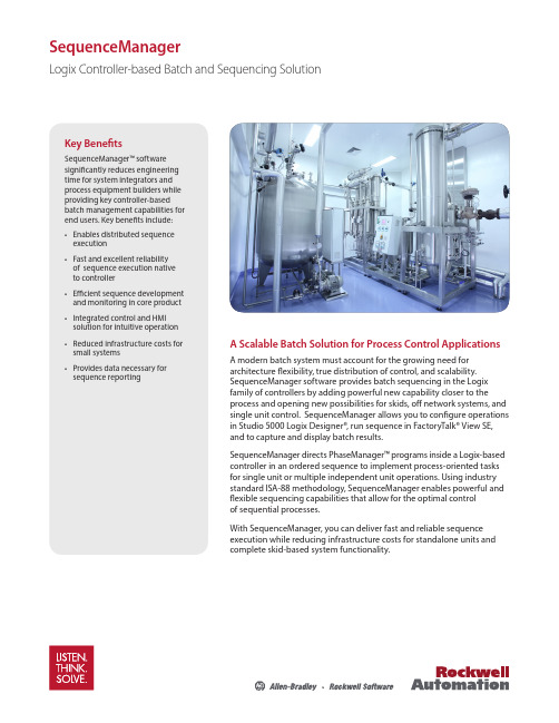
SequenceManagerLogix Controller-based Batch and Sequencing SolutionA Scalable Batch Solution for Process Control ApplicationsA modern batch system must account for the growing need for architecture flexibility, true distribution of control, and scalability. SequenceManager software provides batch sequencing in the Logix family of controllers by adding powerful new capability closer to the process and opening new possibilities for skids, off network systems, and single unit control. SequenceManager allows you to configure operations in Studio 5000 Logix Designer®, run sequence in FactoryTalk® View SE, and to capture and display batch results.SequenceManager directs PhaseManager™ programs inside a Logix-based controller in an ordered sequence to implement process-oriented tasks for single unit or multiple independent unit operations. Using industry standard ISA-88 methodology, SequenceManager enables powerful and flexible sequencing capabilities that allow for the optimal control of sequential processes.With SequenceManager, you can deliver fast and reliable sequence execution while reducing infrastructure costs for standalone units and complete skid-based system functionality.Key BenefitsSequenceManager™ software significantly reduces engineering time for system integrators and process equipment builders while providing key controller-based batch management capabilities for end users. Key benefits include:• Enables distributed sequence execution • Fast and excellent reliability of sequence execution native to controller • Efficient sequence development and monitoring in core product • Integrated control and HMI solution for intuitive operation • Reduced infrastructure costs for small systems • Provides data necessary for sequence reportingDistributed Batch Management Based on Proven TechnologyBuilt Upon Rockwell AutomationIntegrated ArchitectureSequenceManager was built using the standard control and visualization capabilities found in Rockwell Automation® Integrated Architecture® software. SequenceManager is a new capability that is builtinto Logix firmware that uses visualization through FactoryTalk® View SE to create an integrated sequencing solution. Combined with event and reporting tools, SequenceManager software is a complete batch solution for single unit and skid-based process applications.Scalable Controller-based Solution SequenceManager allows flexible design for skid-based equipment to be developed, tested and delivered asa fully functioning standalone solution but, if needed, seamlessly integrated into a larger control system. This strategy provides the end user with the option to integrate equipment without imposing design constraints on the OEM delivering the skid. Additionally, it enables the end user to deliver equipment as a standalone system without the constraint to scale to a larger process solution in the future. This batch solution offers scalability to help prevent costly redesign and engineering.Flexibility to Meet Process Needs SequenceManager enables you to expand your process control on skid based equipment that performs repetitive tasks and decision-making abilities. By using the ISA-88 methodology, SequenceManager allows for control design that can be adopted to fit the needs of the process industries without the constraints of custom application code. Built-in state model handling provides for fast and easy configuration while maintainingcontrol of the process.Editor and ViewerAs a brand new program type in Studio 5000 Logix Designer®, SequenceManager™ software gives the user the power and flexibility necessary to create dynamic recipes to maximize the effectiveness of the process control system.Without limitations on steps and parameters, and the ability to run parallel phases, to branch, and to loop back and rerun steps, SequenceManager removes the barriers in achieving effective batch within the controller.Sequence ExecutionProcedural sequences are executed through nativefunctions in the controller. With an integrated ISA-88 state model, the control and states of phases can be assured. Standard batch functionality, such as manual control and active step changes, are included to give the operational flexibility that is needed to respond toabnormal process conditions.Allowing for an Intuitive Batch ApplicationResponsive batch interactions between the controller and equipment, along with intuitive operator interfaces, provide the core of a truly distributed batching strategy that drives ISA-88 procedural models.Allen-Bradley, FactoryTalk Batch, FactoryTalk® View SE, Integrated Architecture, Listen.Think.Solve., PhaseManager, PlantPAx, Rockwell Automation, Rockwell Software, SequenceManager, and Studio 5000 Logix Designer are trademarks of Rockwell Automation, Inc. Trademarks not belonging to Rockwell Automation are property of their respective companies.Operator ViewerFactoryTalk® View SE and ActiveX controls monitor and interact with a running procedural sequence through the HMI. Advance ActiveX controls provide an intuitive interface for controlling sequences and changingparameters from the operational environment. Improved capabilities allow the user to perform manual step changes and acquire control easily.Reporting and AnalyticsSequenceManager data generates events that are used to produce batch reports and procedural analysis. A separate event client transfers the event data from the Logixcontroller to a historical database. SequenceManager uses the same data structure and reports as FactoryTalk Batch, which provides a consistent and intuitive batch reporting tool among Rockwell Automation® Batch Solutions.Additional InformationVisit us at /processPublication PROCES-PP001A-EN-E – June 2016Copyright © 2016 Rockwell Automation, Inc. All Rights Reserved. Printed in USA.。
Infoblox ActiveTrust数据表说明说明书

Key Features• Infoblox Threat Insight in the Cloud detects DNS based data exfiltration and newer threats such as DNSMessenger, DGA, and Fast Flux. Threat Insightis the only DDI solution that leverages reputation, signatures and behavioral analytics to detect DNS based data exfiltration• Infoblox DNS Firewall executes administrator-defined policy action (block, redirect device to a walled garden site, and/or log event)to help stop devices anytime, anywhere from communicating with C&Cs or botnets via DNS • Infoblox Threat IntelligenceData Exchange (TIDE) collects and manages curated threat intelligence from internal and external sources in a single platform. It enables security operations to remediatethreats more rapidly by sharing normalized TIDE data in real time with third-party security systems such as Palo Alto Networks, SIEM, etc• Infoblox Dossier is a threat investigation tool that provides immediate threat context and allows threat analysts to save precious time, shortening the attack window for criminals• Integration with Security Ecosystem Integration with third-party security systems extends the unique visibility we have into DNS to other security systems such as Qualys and Carbon Black Security ChallengesInternet communications, including malware, rely on DNS. Attackers are taking advantage of DNS as a data-exfiltration and malware control point. Over 91 percent of malware uses DNS for data exfiltration and to communicate with C&C servers or redirect traffic to malicious sites. Existing security controls such as firewalls, email proxies, and web proxies rarely focus on DNS and associated threats.Using unverified threat data residing in silos in your cybersecurity infrastructure is like trying to pick out instruments in an orchestra that is playing outdoors in the midst of rush-hour traffic. The noise blocks out everything you really want to hear. Low-quality data creates nuisance red flags that threat analysts still must track down. They can easily be swamped by false-positives, leaving them unable to detect and prevent genuine threats.T o research information and gather context about threats, analysts must go to multiple tools. The process is manual and time consuming, which slows response and often requires high levels of expertise. In addition, they often lack a centralized tool for threat investigation that aggregates threat and indicator data from multiple sources and quickly shares context.The Infoblox SolutionIntercepting DNS traffic is an ideal approach to counter DNS-based data exfiltration and malware communications with C&C sites. In addition, it is an ideal approach for devices on which endpoint agent software cannot be deployed (e.g. POS, medical equipment, certain IoT devices, etc.). ActiveT rust is a highly efficient, scalable solution that offers:Infoblox DNS Firewall for prevention of malware communications with C&C sites and botnetsIn foblox Threat Insight in the Cloud prevents (with DNS firewall) DNS-based data exfiltrationby uniquely leveraging reputation, signatures, and behavioral analytics. It is also able to block (using DNS firewall) newer threats such as DNSMessenger, DGA, and Fast Flux. Threat Insightin the Cloud is offered as a service to scale in the cloud and is bundled with ActiveTrust Plus and ActiveT rust Advanced.SummaryInfoblox ActiveT rust® proactively detects and prevents cyberthreats. ActiveT rust bundles Infoblox DNS Firewall, InfoBlox Threat Insight in the Cloud, Infoblox Threat Intelligence Data Exchange (TIDE), and Infoblox Dossier. The solution prevents data exfiltration and malware command-and-control (C&C) communications via DNS, centrally aggregates curated internal and external threat intelligence, distributes validated threat data to the customer’s security ecosystem for remediation, and enables rapid investigation to identify context and prioritize threats.ActiveTrust Standard ActiveTrust Plus ActiveTrust AdvancedAnnual SubscriptionLicensed by Appliance by model Organization-wide by number ofprotected usersOrganization-wide by number ofprotected usersInfoblox DNS Firewall Zones(RPZs)Standard (4)Standard (4) + Advanced (7) +SURBL (2)Standard (4) + Advanced (13) +SURBL (2)Infoblox Threat Insight inthe Cloud Not available Included IncludedInfoblox Data via ThreatIntelligence Data Exchange Not available One of:* Hostnames* IP Addresses* URLsAll of:R HostnamesR IP AddressesR URLsInfoblox Dossier No (threat lookup via CloudServices Portal only)32,000 queries/year(supports 2 analysts)65,000 queries/year(supports 4 analysts)Third-party Data viaInfoblox Threat IntelligenceData Exchange (TIDE)Not available Available a la carte Available a la carteHardware Requirements If you intend to use Infoblox DNS Firewall for RPZ-based policy enforcement, you need to buy:One or more Infoblox T rinzic (physical) or vNIOS (virtual) appliances with DNS with recursion enabled. Trinzic models:IB Series: IB-800, IB-1400, IB-2200, IB-4000, and IB-4030PT Series: PT-1400/1405, PT-2200/2205, and PT-4000TE Series (physical and virtual appliances): TE-100, TE-810/815/820/825, TE-1410/1415/1420/1425, TE-2210/2215/2220/2225, and TR-4010/TR-4010-10GESoftware Requirements • If you want Threat Insight in the Cloud, then you can purchase either ActiveTrust Plus or ActiveTrust Advanced license. If you will NOT deploy ActiveT rust threat intelligence data on third-party infrastructure, then buy an ActiveT rust Standard license, which is based on the T rinzic appliance models.• If you intend to deploy ActiveT rust threat intelligence data on third-party infrastructure (e.g. next-generationfi rewall, SIEM, Web proxy), then you can buy either ActiveT rust Plus or ActiveTrust Advanced license. The license is based on total number of protected users’ organization-wide (Grid-wide license). The two products vary based on the amount of data sets that can be applied and total number of annual Dossier threat indica-tor queries that can be transacted.Infoblox Threat Intelligence Data Exchange (TIDE) leverages highly accurate machine-readable threat intelligence (MRTI) datato aggregate and selectively distribute data across a broad range of security infrastructure. Our threat intelligence team curates, normalizes, and refines the high-quality threat data to minimize false positives. Our threat feeds begin with information gained from native investigations and harvesting techniques. We then combine them with verified and observed data from trusted partners including government agencies, academic institutions, several premier Internet infrastructure providers, and law enforcement. The end result is a highly refined feed with a very low historical false-positive rate.Infoblox Dossier threat indicator investigation provides rich threat context to prioritize incidents and respond quickly.Optional Services • Infoblox Threat Insight (on premises) for protection against DNS tunneling and sophisticated data ex fi ltration techniques is available as a separate standalone option for purchase for all AT customers.-Note: this only works on the following Infoblox models: PT-1405, TE-1415/V1415, TE-1425/V1425,TE-2210/v2210, 2215/v2215, TE-2220/v2220, 2225/v2225, PT-2200, PT-2205, IB-4010/v4010, V4015,TE-V4010/V4015, PT-4000, IB-4030-DCAGRID-AC/DC, IB-4030-DCAGRID-T1-AC/DC, IB-4030-DCA-GRID-T2-AC/DC, and IB-4030-DCAGRID-T3-AC/DC.• Infoblox Security Ecosystem license enables integration of Infoblox DNS RPZ/Firewall with third-party security systems: FireEye, Qualys and threat intelligence platforms.• Infoblox Dossier (portal, 65,700 queries package) 1-year subscription-ActiveTrust Standard customers can purchase if they want to perform threat investigation, since Dossier is not bundled with ActiveTrust Standard.-ActiveTrust Plus and ActiveT rust Advanced customers that need additional queries beyond what is provid-ed in the base product can also purchase this:-Third-party marketplace threat feeds-Prerequisite: ActiveTrust Plus or ActiveT rust Advanced must be purchased in order for customers topurchase and subscribe to one or more 3rd party marketplace threat feeds-Does NOT Include Maintenance/Support• Infoblox Reporting and Analytics (appliance) – provides rich reporting on Infoblox DNS Firewall (top RPZ hits, top malicious hostnames, users)Note: The SURBL (an Infoblox premium threat intelligence data partner) OEM license is bundled with the ActiveT rust Plus and ActiveT rust Advanced bundles for use by Infoblox DNS Firewall. The Infoblox ActiveT rust and SURBL data sets (Multi-domain and Multi Lite domain) are complementaryand if used together, can enable increased threat coverage. T o learn more about the Infoblox threat intelligence data, please refer to the solution note “Overview of Infoblox Threat Intelligence for ActiveT rust” on the Infoblox website.Key BenefitsWith Infoblox ActiveT rust, you get actionable network intelligence with flexible threat intelligence integrated into your DDI enthronement. this enables you to proactively detect, investigate, prioritize, remediate, and prevent cyber threats.Prevent DNS-based Data exfiltration at Scale in the CloudWith Threat Insight in the Cloud, you can detect and block (with DNS Firewall) DNS-based data exfiltration using a combination of reputation, signature, and behavioral analysis.Detect and Block DNSMessenger, DGA, and Fast FluxOffered as a service, Threat Insight in the Cloud can also detect and block (with DNS Firewall) new threats such as DNSMessenger, DGA, and Fast Flux.Stop DNS-based Malware C&C/botnet CommunicationsWith Infoblox DNS Firewall, you gain proactive network protection against fast-evolving, elusive malware threats that exploit DNS to communicate with C&C sites.Collect and Manage Curated Threat Intelligence from Internal and External Sources in a Single PlatformInfoblox TIDE enables you to aggregate, normalize, and manage internal and multiple third-party threat intelligence data in a single location, preventing siloed and disjointed threat intel.Improve Security Posture by Sharing Curated Threat Intelligence Data in Real Time with Security EcosystemsCreating custom API data feeds built for specific use cases is quick and easy. Combine threat data from all your sources, use contextual metadata to select the relevant subset, and leverage the right format such as JSON, STIX, CSV, CEF, and RPZ to RPZto improve the security posture and situational awareness of your existing security ecosystem, such as NGFW, IPS, web proxy,and SIEM.Extend the Unique Visibility Infoblox Provides into DNS such as Indicators of Compromise (IoCs) to Other Security Systems Infoblox provides the unique visibility into DNS data as the market-leading vendor of DDI that other vendors cannot match. DNS data such as indicators of compromise (IoC) can be shared with other security systems such as vulnerability scanners (Qualys and Rapid7) to kick off a scan when a new device comes on the network to determine whether it is malware infected.Expedite Threat Investigation to Free Up Security Personnel and Provide Timely Access to Context for Threat Indicators Use the Infoblox Dossier research tool as a single source of truth to rapidly understand the types of threats happening on your network, where they are coming from, and the risks they pose to your organization, including understanding the data source, threat severity, and priority. Gain insight into questionable activities related to inbound or outbound network communications. Furthermore, quickly learn about and understand what a variety of trusted sources report about the indicator in question to improve the operational efficiency of scarce security operations resources, saving you time and effort.About InfobloxInfoblox delivers Actionable Network Intelligence to enterprises, government agencies, and service providers around the world. As the industry leader in DNS, DHCP, and IP address management (DDI), Infoblox provides control and security from the core—empowering thousands of organizations to increase efficiency and visibility, reduce risk, and improve customer experience.Corporate Headquarters: +1.408.986.4000 1.866.463.6256(toll-free,U.S.andCanada)********************。
智慧图书馆建设标准探析

DOI:10.13530/ki.jlis.2021002智慧图书馆建设标准探析”卢小宾宋姬芳蒋玲洪先锋刘静张藕摘要“智慧图书馆”理念于2003年被首次提出,代表一种不受空间限制、可感知的移动图书馆服务,旨在帮助用户快速便捷地找到所需要的文献信息资源。
目前,智慧图书馆的建设尚处于探索阶段,构建科学、合理、完备的标准体系对智慧图书馆的健康发展至关重要。
本文从智慧图书馆的资源建设、服务模式和技术应用等核心要素入手,对比分析国内外已有的图书馆建设相关标准,探索我国智慧图书馆建设标准的选采策略,提出我国智慧图书馆建设标准体系的构建对策:①重视多维度标准体系构建,保障智慧图书馆建设行稳致远;②注重与现有标准体系的融合,适应国家政策要求与行业发展变化;③深化标准制定领域的国际合作,提升我国智慧图书馆相关标准的话语权;④推动制定主体多元化,提升智慧图书馆标准体系的科学性与完备性。
表70参考文献39。
关键词图书馆智慧图书馆建设标准标准体系分类号G250.1Study on the Construction Standards of Smart LibraryLU Xiaobin,SONG JifangJIANG Ling,HONG Xianfeng,LIU Jing&ZHANG RuABSTRACTThe concept"smart library"was first put forward in2003.It refers to a perceptible mobile library service which is not limited by space and helps users find the information resources conveniently.The construction of smart libraries is still in its exploratory stage.Current research mainly focuses on the definition,characteristics,content and functions,while the fact that there is less discussion on the construction standards of smart libraries delays the implementation and development to a certain extent. Therefore,it is significant to create a scientific,reasonable and complete standard system for the sound development of smart libraries.This article begins with the discussion of the core elements such as resource construction,service mode and technology application of smart libraries,compares and analyzes the relevant standards of smart library construction at home and abroad,and then explores the strategies of deciding on the corresponding construction standards of smart libraries in China:1)In smart transformation,the standards of resource construction of Chinese libraries should draw on achievements abroad.To conform to actual conditions in China,the standard system of smart libraries should be built on the construction of core collection,physical digitization,a resource sharing cooperation network,*本文系教育部学校规划建设发展中心委托项目“雄安大学数字图书馆建设策略研究”的研究成果之一。
operating system《操作系统》ch11-file system implementation-50

I/O Using a Unified Buffer Cache
11.32
11.7 Recovery
Consistency checking – compares data in directory structure with data blocks on disk, and tries to fix inconsistencies
Brings all pointers together into the index block. Logical view.
index table
11.20
Example of Indexed Allocation
11.21
Indexed Allocation (Cont.)
Need index table Random access Dynamic access without external fragmentation, but
Efficiency dependent on:
disk allocation and directory algorithms types of data kept in file’s directory entry
Performance
disk cache – separate section of main memory for frequently used blocks
File-allocation table (FAT) – disk-space allocation used by MS-DOS and OS/2.
11.17
Linked Allocation
11.18
File-Allocation Table
Oracle Autonomous Health Framework (AHF) 概述说明书

Oracle Database Autonomous Health FrameworkFrequently Asked QuestionsQ:What is Oracle Autonomous Health Framework (AHF)?A:Oracle Autonomous Health Framework (AHF) presents the next generation of tools as components, which work together autonomously 24x7 to keep database systems healthy and running while minimizing human reaction time.Utilizing machine-learning technologies, Oracle AHF provides early warning or automatically solves operational runtime issues faced by Database and System administrators in the areas of availability and performance.Q:What is autonomous in Oracle Autonomous Health Framework (AHF)?A:Autonomous in Oracle Autonomous Health Framework refers to the fact that the components in the framework require miminal human intervention to do their work. They run 24x7 in their daemon mode to resolve the operational runtime issues in the database system in the space of availability and performance. These components of Oracle AHF include Cluster Health Monitor (CHM), ORAchk, Cluster Verification Utility (CVU), Cluster Health Advisor (CHA), Trace File Analyzer (TFA), Quality of Service Management (QoSM), Hang Manager, and Memory Guard.Q:What kind of Availability issues can be resolved with Oracle Autonomous Health Framework (Oracle AHF)?A:Oracle AHF resolves runtime issues that threaten the availability of the software stack either through a software issue (DB, GI, OS) that can cause the database or one of its instances to become unresponsive, or the issues with the underlying hardware resources (CPU, Memory, Network, Storage) that can cause a server to be evicted from the cluster and shut down all the database instances running there.Q:What kind of Performance issues can be resolved with Oracle Autonomous Health Framework (Oracle AHF)?A:Oracle AHF resolves the runtime issues that threaten the performance of the system as seen by the database client or application either due to software issues (bugs,configuration, contention, etc.), or client issues (demand, query types, connection management, etc).Q:What are the different components in Oracle Autonomous Health Framework?A:Oracle Autonomous Health Framework consists of both new components such as Cluster Health Advisor and Hang Manager and already existing tools as components that run in daemon mode such as ORAchk, Cluster Verification Utility, Cluster Health Monitor, Cluster Trace File Analyzer, Quality of Service Management, and Memory Guard.These components work 24x7 autonomously (in daemon mode) to address performance and availability issues.Q:How does Oracle Autonomous Health Framework (Oracle AHF) resolve availability and performance issues?A:Oracle AHF components work 24x7 in daemon mode to address the availability and performance issues, and ensure high availability for the database system. They collaborate with each other to provide a framework that continuously monitors the database system, maintains best practice configurations, and alerts about vulnerability to known issues. It monitors performance of the database system autonomously and manages resources to maintain SLAs. It also preserves resource availability during common situations of memory stress and resources being blocked by hung sessions. Oracle AHF uses machine learning to even discover potential cluster and database problems, and notifies with corrective actions to prevent the issues altogether. And finally, for the issues that are hard to detect and require Oracle Support, Oracle AHF speeds the issue diagnosis, triage and resolution process.Q:Is Oracle Autonomous Health Framework integrated with Enterprise Manager?A:Currently, Oracle AHF components - Cluster Health Monitor (CHM), Quality of Service Management (QoSM), ORAchk and Cluster Health Advisor (CHA) are integrated with Enterprise Manager. Hang Manager and Memory Guard use EMCC to send alert notifications.Q:Where can I see the output for checks performed by Cluster Verification Utility (CVU)?A:Users can access the results of CVU checks through its generated report in text or HTML file format. These reports can also be saved for later reference.Q:Hang Manager resolves hangs autonomously. How do I know if a session is being terminated in the process?A:Hang Manager detects and resolves hangs autonomously.However, it continuously logs all detections and resolutions in DB Alert Logs. So, if a session is terminated, it will belogged in these alert logs. The details of complete hangresolution are also available in dump trace files.Q:Where can I find details of actions performed by Memory Guard to relieve memory stress?A:Even though Memory Guard works autonomously, actions performed by it are logged in the audit logsunder $ORACLE_BASE/crsdata/nodename/qos/logs/dbwlm/auditing.Q:Is Oracle Autonomous Health Framework a Real Application Clusters -only feature?A:Oracle Autonomous Health Framework compoents Cluster Health Advisor, and Quality of Service Management require Oracle Real Application Clusters database deployments.However, other components of Oracle Autonomous Health Framework, Memory Guard, ORAchk, Cluster Verification Utility, Cluster Health Monitor, Hang Manager, and Trace File Analyzer do not.Q:Is Oracle Autonomous Health Framework a 12.2-only feature?A:Oracle Autonomous Health Framework as a framework is a12.2 only feature. However, Oracle Autonomous HealthFramework components, Cluster Verification Utility, ORAchk, and Trace File Analyzer, have been in existence even before 12.2 in non-daemon mode. In Oracle Autonomous Health Framework, they have now been launched in their daemon mode where the components work together with other AHF ones to resolve operational runtime issues related to availability and performance in the database system.Q:What is Cluster Health Advisor?Oracle Autonomous Health Framework component Cluster Health Advisor (CHA) uses machine learning to provide system and database administrators with early warning of pending performance issues, and root causes and corrective actions for Oracle RAC databases and cluster nodes. It also sends warning messages generated to Enterprise Manager Cloud Control. When Grid Infrastructure (GI) is installed for RAC or RAC One Node database, Cluster Health Advisor is automatically enabled by default. Q:Most of the components in Oracle Autonomous Health Framework are the tools that I already use. How is Oracle Autonomous Health Framework different?A:Even though components of Oracle Autonomous Health Framework already exist, their value in Oracle AHF comes from the fact that they run 24x7 in daemon mode working together to resolve runtime issues related to performance and availability in the database systems.Q:What is Collections Manager in Oracle Autonomous Health Framework?A:Collection Manager in Oracle Autonomous Health Framework is an Apex application that provides a single view of the health of all the clusters in the database system and helps to identify the availability and performance issues related to best practices and compliance. Each time ORAchk performs its checks, the output (collection) is uploaded into the Collection Manager database. Collection Manager aggregates the data from these collections to display the database system health. With Collection Manager, the user can browse either an individual collection to understand the system health at a give time, compare two collections to assess the change in health of the system over time, or browse multiple collections at a time based on various parameters such as platform, DB version, etc.Q:How does Hang Manager resolve hangs?A:Hang Manager autonomously detects and resolves hangs.A hang occurs when a chain of one or more sessions isblocked by another session and are not able to make any progress. Usually, these chains of sessions have a root ora final blocker session which blocks all the other sessionsin the chain called the victim session. Once a victim session is selected, Hang Manager applies hang resolution heuristics on the victim. If the chain of sessions or the hang resolves itself automatically, then Hang Manager does not take any action. However, if the hang does not resolve itself, then Hang Manager may resolve the hang by terminating the victim session or if that is unsuccessful, then terminating the process.Q:Where can I find more information about Oracle Autonomous Health Framework?Information on Oracle Autonomous Health Framework isavailable on OracleTechNetwork:/goto/ahf2 | Oracle Autonomous Health Famework FAQ3 | Oracle Autonomous Health Famework FAQOracle Autonomous Health Framework also has its own user guide which can be referred to at:/database/122/ATNMS/toc.htm Q: Do I need a separate license for Oracle AutonomousHealth Framework?Oracle Autonomous Health Framework consists of multiple components. Oracle Autonomous Health Framework compoents Cluster Health Advisor and Quality of Service Management, require an Oracle RAC license. However, the other components, Cluster Health Monitor, Cluster Verification Utility, ORAchk, Trace File Analyzer, Memory Guard, and Hang Manager do not. Please follow this link to the license guide for more information:/database/122/DBLIC/toc.htmOracle Corporation, World Headquarters 500 Oracle ParkwayRedwood Shores, CA 94065, USACO N N E C T W I T H U S /blogs /oracle /oracle 。
税收支付系统接口用户指南说明书
Tax Payment System Interface User Guide Oracle FLEXCUBE Universal Banking Release 12.2.0.0.0Part No. E74659-01May 2016Tax Payment System Interface User GuideOracle Financial Services Software LimitedOracle ParkOff Western Express HighwayGoregaon (East)Mumbai, Maharashtra 400 063IndiaWorldwide Inquiries:Phone: +91 22 6718 3000Fax: +91 22 6718 3001/financialservices/Copyright © 2007, 2016, Oracle and/or its affiliates. All rights reserved.Oracle and Java are registered trademarks of Oracle and/or its affiliates. Other names may be trademarks of their respective owners.U.S. GOVERNMENT END USERS: Oracle programs, including any operating system, integrated software, any programs installed on the hardware, and/or documentation, delivered to U.S. Government end users are “commercial computer software” pursuant to the applicable Federal Acquisition Regulation and agency-specific supplemental regulations. As such, use, duplication, disclosure, modification, and adaptation of the programs, including any operating system, integrated software, any programs installed on the hardware, and/or documentation, shall be subject to license terms and license restrictions applicable to the programs. No other rights are granted to the U.S. Government.This software or hardware is developed for general use in a variety of information management applications. It is not developed or intended for use in any inherently dangerous applications, including applications that may create a risk of personal injury. If you use this software or hardware in dangerous applications, then you shall be responsible to take all appropriate failsafe, backup, redundancy, and other measures to ensure its safe use. Oracle Corporation and its affiliates disclaim any liability for any damages caused by use of this software or hardware in dangerous applications.This software and related documentation are provided under a license agreement containing restrictions on use and disclosure and are protected by intellectual property laws. Except as expressly permitted in your license agreement or allowed by law, you may not use, copy, reproduce, translate, broadcast, modify, license, transmit, distribute, exhibit, perform, publish or display any part, in any form, or by any means. Reverse engineering, disassembly, or decompilation of this software, unless required by law for interoperability, is prohibited.The information contained herein is subject to change without notice and is not warranted to be error-free. If you find any errors, please report them to us in writing.This software or hardware and documentation may provide access to or information on content, products and services from third parties. Oracle Corporation and its affiliates are not responsible for and expressly disclaim all warranties of any kind with respect to third-party content, products, and services. Oracle Corporation and its affiliates will not be responsible for any loss, costs, or damages incurred due to your access to or use of third-party content, products, or services.Contents1. Preface ......................................................................................................1-11.1 Introduction..............................................................................................................1-11.2 Audience..................................................................................................................1-1Accessibility.................................................................................... 1-11.3 Documentation1.4 Organization............................................................................................................1-11.5 Acronyms and Abbreviations................................................................................... 1-21.6 Organization............................................................................................................1-21.7 Glossary of Icons..................................................................................................... 1-21.8 Related Documents................................................................................................. 1-22. Oracle FLEXCUBE – Tax Payment Interface .........................................2-12.1 Details for Tax Payment Interface........................................................................... 2-12.1.1 Maintaining Interface Parameterization...................................................... 2-1Files......................................................................................................... 2-22.2 Incoming2.2.1 Incoming File Format.................................................................................. 2-22.3 Customer Tax Payment Report............................................................................... 2-32.3.1 Contents of the Report............................................................................... 2-33. Function ID Glossary ...............................................................................3-11. Preface 1.1 IntroductionThis manual is designed to help acquaint you with the interface between Oracle FLEXCUBE and Tax Payment System.This manual provides you extensive explanations about the maintenances and processing with respect to the interface. Besides this User Manual, while maintaining the details, you can invoke the context sensitive help available for each field. This help encapsulates the purpose of each field within a screen. Placing the cursor on the relevant field and striking the <F1> key on the keyboard can obtain information specific to a particular field. 1.2 AudienceThis manual is intended for the following User/User Roles:1.3 Documentation AccessibilityFor information about Oracle's commitment to accessibility, visit the Oracle Accessibility Program website at /pls/topic/lookup?ctx=acc&id=docacc.1.4 OrganizationThis manual is organized as follows:RoleFunction Back office data entry ClerksInput functions for maintenances Back office Managers/Officers Authorization functions ChapterDescription Chapter 1About this Manual gives information on the intended audience. Italso lists the various chapters covered in this User Manual.Chapter 2Oracle FLEXCUBE – Tax Payment Interface helps you understandthe interfaced Tax Payment System for exchange of the tax paymentdetails of customers.Chapter 3Function ID Glossary has alphabetical listing of Function/Screen ID'sused in the module with page references for quick navigation.1.5 Acronyms and Abbreviations 1.6 OrganizationThis document talks about the required maintenance and further processing of data transfer between Oracle FLEXCUBE and FGL. This includes the following:● Processing Incoming Files● Generating Customer Tax Payment Report● Screen Glossary1.7 Glossary of IconsThis User Manual may refer to all or some of the following icons.1.8 Related DocumentsYou can refer to the following documents:● XML Interface Document● Procedures User Manual● Oracle FLEXCUBE Generic Interface User Manual AbbreviationDescription System Unless and otherwise specified, it shall always refer to OracleFLEXCUBE systemIcons FunctionExitAdd rowDelete rowOption List2. Oracle FLEXCUBE – Tax Payment InterfaceOracle FLEXCUBE interfaces with the Tax Payment System for exchange of the tax paymentdetails of customers. This interface also helps you view the reports related to customers’ taxpayments.This chapter contains the following sections:● Section 2.1, "Details for Tax Payment Interface"● Section 2.2, "Incoming Files"● Section 2.3, "Customer Tax Payment Report"2.1 Details for Tax Payment InterfaceThis section contains the following topic:● Section 2.1.1, "Maintaining Interface Parameterization"The following are maintained for Tax Payment interface, internally:● Details of External System (EXTSTPS)● Details of the Interface● Interface Parameterization.For further details on maintaining external system and interface, refer to the Oracle FLEXCUBE Generic Interface user manual.ParameterizationInterface2.1.1 MaintainingFor tax payment interface, you need to maintain the interface parameterization details. Toinvoke the ‘Interface Parameterization’ screen, type ‘IFDPARAM’ in the field at the top rightcorner of the Application toolbar and click the adjoining arrow button.Specify the following details:Interface CodeSelect the interface code from the adjoining option list. This list displays all interface codesmaintained in the system.Parameter NameSpecify a unique parameter name for the interface upload.Parameter ValueSpecify the default values assigned for every unique parameter name and interface code.Account DescriptionSpecify the description of the selected parameter is here.Files2.2 IncomingOracle FLEXCUBE picks up the file containing the tax payment details of customers from theintermediate data store. This file contains the following information:● Customer account number● Tax amountThe system further debits the tax amount from the customer account and credits the'SIMPATI' GL.The system will not process if the records are empty or does not contain mandatory fields.Before passing the accounting entries, the system checks whether sufficient balance isavailable in the account. In case of insufficient balance, the transaction is rejected.This section contains the following topic:● Section 2.2.1, "Incoming File Format"2.2.1 Incoming File FormatThe file format is given below:Attribute Name Attribute ValueInterface Type IncomingFrom System EXTSTPSTo System FLEXCUBETo be ConfirmedDirectory Loca-tionFile Name TxPmt$Y$M$D$H$M$S.txtFrequency DailyCharacter Set ASCIIFile Header NoFile Footer NoDelimiter |Record Length VariableFormat Line Sequential, Variable Length Records2.3 Customer Tax Payment ReportYou can generate and view customer tax payment reports using ‘Customer Tax Payment’ screen. To invoke the screen, type ‘IFRTXPM’ in the field at the top right corner of theApplication toolbar and click the adjoining arrow button. To generate the report, you need to specify the following details:Branch CodeThe system displays the branch code.Account NumberSpecify the account number for which you need to generate the tax payment report. Assessment YearSpecify the assessment year. The tax payment report will contain the details of payment of tax during the assessment year specified here.From DateYou need to indicate period. Specify the start date of the tax payment report period here. The system will generate the report for the period from this date.To DateYou need to indicate period. Specify the end date of the tax payment report period here. The system will generate the report for the period from the start date until this date.Once you have captured the details, click ‘Ok’ button. The system generates and displays the tax payment report for the selected account and period.2.3.1 Contents of the ReportThe tax payment report contains the following details:End of theRecordCR/LF Numeric paddingNo Text padding No● Report name● Branch code● Assessment year● Period● Source● Customer number● Account number● Taxable amount● Paid amount● Payment date● Tax reference number3. Function ID GlossaryIIFDPARAM........................2-1IFRTXPM..........................2-3。
LabVIEW 8.6 Datalogging and Supervisory Control Mo
RELEASE AND UPGRADE NOTESLabVIEW Datalogging and™Supervisory Control ModuleVersion 8.6This document describes the system requirements and the process ofinstalling the LabVIEW8.6 Datalogging and Supervisory Control (DSC)Module and the DSC Module8.6 Run-Time System. This document alsodescribes the new features available with version8.6 and compatibility andupgrade issues you might encounter when you use version8.6.To upgrade the DSC Module from 7.x or earlier, refer to the LabVIEW8.2Datalogging and Supervisory Control Module Release and Upgrade Notes.The Upgrading from the LabVIEW DSC Module7.x section providesimportant information for upgrade users. Refer to the National InstrumentsWeb site at /info and enter the info code dsc820 to access theLabVIEW8.2 Datalogging and Supervisory Control Module Release andUpgrade Notes.Refer to the Getting Started with the LabVIEW Datalogging andSupervisory Control Module manual for exercises you can complete tofamiliarize yourself with the DSC Module.ContentsSystem Requirements (2)Installation Instructions (2)Activating the LabVIEW License (Windows) (3)Evaluating LabVIEW, Modules, or Toolkits (4)Single-Seat and Multi-Seat Licensing (4)New Features in the DSC Module8.6 (4)Enhancements to the NI Distributed System Manager (5)New Example VIs (5)Performance Improvements (5)Compatibility Issues (5)Considerations for the DSC Module Run-Time System (6)Known Issues (6)System RequirementsTo use the DSC Module, your computer must meet the following minimumsystem requirements:•Windows Vista, Windows XP Service Pack 2, or Windows 2000Service Pack 4.•800MB free disk space.•512MB of RAM. National Instruments recommends 1GB of RAM.•LabVIEW8.6 Base, Full, or Professional Development System. Referto the LabVIEW Release Notes for the LabVIEW system requirements.The DSC Module does not support Windows NT/Me/98/95/Server2003. Installation InstructionsRefer to /support if you encounter errors during installation.You can install the DSC Module8.6 by using the LabVIEW PlatformDVDs or the CDs.The LabVIEW Platform DVDs contain LabVIEW, the DSC Module, otheradd-ons, and device drivers. You can install and activate both LabVIEWand the DSC Module by using the LabVIEW Platform DVDs. If youinstalled LabVIEW, the DSC Module, and the appropriate NI device driversfrom the LabVIEW8.6 Platform DVD, you do not need to reinstall usingthe CDs described in this section. Refer to the LabVIEW Release Notes formore information about installing the LabVIEW development system.The CDs contain the DSC Module only. Complete the following steps toinstall the DSC Module from the CD.1.Log in to the development computer as an administrator or as a userwith administrative privileges.2.Install LabVIEW8.6 from the LabVIEW8.6 installation CD. Referto the LabVIEW Release Notes for information about installing theLabVIEW development system.3.Install the DSC Module from the LabVIEW8.6 DSC Moduleinstallation CD. Follow the instructions that appear on the screen.4.Follow the directions on the screen to activate your DSC Module.Refer to the Activating the LabVIEW License (Windows) section ofthis document for more information about activating LabVIEW.5.Restart the computer.The DSC Module installs program files, documentation, and examples. LabVIEW DSC Module Release and Upgrade © National Instruments Corporation 3LabVIEW DSC Module Release and Upgrade Notes Note By default, the NI Keyboard Filter Driver is not installed. The NI Keyboard Filter Driver activates special security features, including the ability to restrict users fromswitching between applications by pressing the <Alt-Tab> keys. This driver does not work on laptop computers or on computers with hibernation enabled.Activating the LabVIEW License (Windows)Note (Mac OS and Linux) LabVIEW does not require activation.National Instruments uses activation to better support evaluation of oursoftware, to enable additional software features, and to support licensemanagement in large organizations. To find out more about NationalInstruments software licensing, visit /activate to find frequentlyasked questions, resources, and technical support.You can activate licenses you have purchased for LabVIEW, modules, andtoolkits during installation. If you do not activate a valid license forLabVIEW or any modules or toolkits that you install, the unlicensedproduct operates in evaluation mode. After you install the product, theevaluation begins the first time you launch the product and lasts30consecutive days. When the evaluation period expires, you must activatea valid license to continue using the product.To activate the product license, use the serial number you received on theCertificate of Ownership included in the software kit. If your software kitdoes not include a Certificate of Ownership, you can find the serial numberon the product packing slip or on the shipping label. You can activate theLabVIEW license in any of the following ways:•During installation, enter the serial number when prompted and complete the installation and activation process.•After you launch LabVIEW in evaluation mode, click the Activate Products button in the LabVIEW dialog box.•Select Help»Activate LabVIEW Components while LabVIEW isrunning in evaluation mode or select Start»All Programs»National Instruments»NI License Manager to launch NI LicenseManager. The license activation does not take effect until you restartLabVIEW.If you do not activate LabVIEW, modules, or toolkits during installation,LabVIEW prompts you for activation when you launch LabVIEW. Afteryou activate the licenses for all LabVIEW products you installed, you nolonger see this prompt.Evaluating LabVIEW, Modules, or ToolkitsYou can access all the tools, VIs and functions, help, and examplesavailable to the LabVIEW Professional Development System and mostmodules or toolkits in a free 30-day evaluation mode.After the evaluation period for a module or toolkit expires, you are nolonger able to perform the following actions:•Run VIs that use VIs from the module or toolkit.•Run VIs from the module or toolkit.•Build VIs that use VIs from the module or toolkit into an executable orshared library.•Access menus, tools, or palettes installed by the module or toolkit.When you install a module or toolkit for evaluation, you install the help forthe module or toolkit. The help for the module or toolkit remains installedafter the 30-day evaluation period. Also, the NI Example Finder displaysall module or toolkit examples after the 30-day evaluation period. You mustuninstall the module or toolkit to remove the help and examples.If you run LabVIEW in evaluation mode, you receive functionality of theProfessional Development System. If you then purchase and activate aLabVIEW license, you receive full functionality of the development systemyou purchase. For example, if you create a VI using tools and subVIs thatare only available in the Professional Development System and then youpurchase and activate the Full Development System, the VI you createdusing Professional Development System features will be broken.Single-Seat and Multi-Seat LicensingLabVIEW supports both single-seat and multi-seat licenses. Single-seatlicensing is the use of LabVIEW on up to three computers but by onlyone user. Multi-seat, or volume, licensing is the use of LabVIEW onseveral computers or by several users. Each seat using LabVIEW musthave a valid license from a license server. Refer to the National InstrumentsWeb site at /license for more information.New Features in the DSC Module8.6The following sections describe the new features in the DSC Module8.6.Refer to the LabVIEW Help, available by selecting Help»Search theLabVIEW Help, for more information about using these new features. LabVIEW DSC Module Release and Upgrade Enhancements to the NI Distributed System ManagerUse the NI Distributed System Manager to create and monitor sharedvariables, network variables, processes, and I/O servers. You also can usethe System Manager to manage security and aliases. In LabVIEW, selectTools»Distributed System Manager to launch the System Manager.The DSC Module adds the following features to the System Manager:•Configuring alarms by using the Auto View and Probe views.•Monitoring alarms and events by using the Alarms and Events views.•Acknowledging alarms and events by using the Alarms and Eventsviews.New Example VIsThe DSC Module provides the following two new example VIs:•Boiler—This example simulates a boiler HMI monitoring station.•HVAC—This example simulates a heating and ventilation airconditioning (HV AC) system.Use the NI Example Finder, available by selecting Help»Find Examples,to launch these and other example VIs.Performance ImprovementsLabVIEW8.6 improves the edit-time and run-time performance of sharedvariables. LabVIEW also improves the launching performance androbustness of the Shared Variable Properties dialog box. The DSCModule8.6 takes advantage of these improvements. Compatibility IssuesIf you open a VI saved in the DSC Module8.2 or earlier, the VI might bebroken if the VI contains an indicator, constant, or control created from theshared variable value change notification output of the following VIs:•Cancel Value Change Notifications VI•Enable Value Change Notifications VI•Request Value Change Notifications VITo fix the broken VI, delete the indicator, constant, or control. Then createa new indicator, constant, or control from the shared variable valuechange notification output and wire it to the appropriate parameter.© National Instruments Corporation5LabVIEW DSC Module Release and Upgrade NotesConsiderations for the DSC Module Run-Time SystemTo run applications built with LabVIEW, the DSC Module, and theLabVIEW Application Builder on a computer without the DSC Moduleinstalled, you must install the DSC Module Run-Time System on thatcomputer. The DSC Module Run-Time System contains components thatenable the DSC features in the built applications.To use the DSC Module Run-Time System, a computer must meet thefollowing minimum system requirements:•Windows Vista, Windows XP Service Pack 2, or Windows 2000Service Pack 4.•700MB free disk space.•512MB of RAM.Complete the following steps to install the DSC Module Run-Time System.1.Log in to the computer as an administrator or as a user withadministrative privileges.2.Install the DSC Module8.6 Run-Time System from the LabVIEW8.6Platform DVDs or LabVIEW8.6 DSC Module Run-Time Systeminstallation CD.3.Follow the instructions that appear on the screen.4.Restart the computer.Known IssuesRefer to the readme_DSC.html file, available by selecting Start»AllPrograms»National Instruments»LabVIEW8.6»Readme or on theDSC Module installation media, for information about known issues withthe DSC Module.Refer to the readme_DSC_RTS.html file, available by selecting Start»AllPrograms»National Instruments»LabVIEW8.6»Readme or on theDSC Module Run-Time System installation media, for information aboutknown issues with the DSC Module Run-Time System.LabVIEW DSC Module Release and Upgrade National Instruments, NI, , and LabVIEW are trademarks of National Instruments Corporation.Refer to the Terms of Use section on /legal for more information about NationalInstruments trademarks. Other product and company names mentioned herein are trademarks or tradenames of their respective companies. For patents covering National Instruments products, refer to theappropriate location: Help»Patents in your software, the patents.txt file on your media, or/patents. Refer to the LabVIEW Help for a listing of the conditions and disclaimers.© 2005–2008 National Instruments Corporation. All rights reserved.374128D-01Jun08。
- 1、下载文档前请自行甄别文档内容的完整性,平台不提供额外的编辑、内容补充、找答案等附加服务。
- 2、"仅部分预览"的文档,不可在线预览部分如存在完整性等问题,可反馈申请退款(可完整预览的文档不适用该条件!)。
- 3、如文档侵犯您的权益,请联系客服反馈,我们会尽快为您处理(人工客服工作时间:9:00-18:30)。
T-SIX:An Indexing System for XML SiblingsSungRan ChoL3S,University of Hannoverscho@l3s.deABSTRACTWe present a system for efficient indexed querying of XML doc-uments,enhanced with sibling operations.R-tree index proposed in[5]has a very high cost for the following-sibling and preceding-sibling axes.We develop a family of index structures,which we refer to as transformed split-tree indexes,to address this problem, in which(i)XML data is horizontally split by a simple,yet efficient criteria,(ii)the split value is associated with tree labeling,(iii)all data elements are transformed into new dimensions to avoid possi-ble overlap between bounding boxes representing data elements in the split tree.The T-SIX system incorporates building transformed split-tree index for XML documents as well as query processing on all XPath axes to provide query answers.1.INTRODUCTIONEfficient querying XML documents is an increasingly important is-sue considering the fact that XML becomes the de facto standard for data representation and exchange over the Web,and XML data in diverse data sources and applications is growing rapidly in size. Given the importance of XPath based query access,XML query evaluation engines need to be able to efficiently identify the ele-ments along each location step in the XPath query.In this context, several index structures for XML documents have been proposed [4,5,7,8,10],in a way to efficiently querying XML documents. As XML documents are modeled by a tree structure,a numbering scheme,labeling tree elements,allows for managing the hierarchy of XML data.For example,each element has the position,a pair of its beginning and end locations in a depthfirst search.In general, the numbering approach has the benefit of easily determining the ancestor-descendant relationship in a tree.In this respect,R-tree index using node’s preorder and postorder,we refer to as whole-tree indexes(WI),has been proposed in[5].Such index,however, does not consider issues related to the costs of the preceding-sibling and following-sibling axes.In this paper,we develop index techniques to reduce the cost of XML siblings.It also addresses an issue of what efficient pack-ing for XML tree data is.An efficient packing method for a tree Copyright is held by the author/owner.Eighth International Workshop on the Web and Databases(WebDB2005), June16-17,2005,Baltimore,Maryland.is not only to group together data elements which are close in a tree,but also to reduce dead space resulting in false positives(no data in indexed space).In the WI,packing method,taking a whole tree,may cover considerable dead space,which influences query-ing XML siblings.We design the transformed split-tree index to address the problem,in which(i)an XML tree is horizontally split by the simple,but efficient criteria,(ii)the split value is associated with tree labeling,(iii)all data elements are transformed into new dimensions to avoid possible overlap between bounding boxes rep-resenting data elements in the split tree.To take advantage of the semantics of the index structure,we develop novel index lookup algorithms for XPath axes for the transformed split-tree index. We describe T-SIX,a system for indexed querying enhanced with XML sibling operations.T-SIX incorporates tree labeling and co-ordinate transformation for XML documents.T-SIX implements novel index lookup algorithms for querying,providing query an-swers for the entire set of XPath query axes.This demonstration is organized as follows.Section2shows the architecture of T-SIX.Section3gives the structure of our index and describes functionality and features that T-SIX encompasses.2.Figure1:Architecture of T-SIXT-SIX is a Java-based prototype.Its architecture is depicted in Figure1.It consists of two main components:the transformed split-tree index management module and the XPath querying mod-ule.Thefirst component implements various aspects of managing transformed split-tree index including tree labeling and coordinate transformation.It accepts the split value of a tree through a graph-ical interface and builds the index based on the value.The secondcomponent implements a query processor on all XPath axes,that accepts queries and returns desired elements.3.DEMONSTRATION OUTLINEThe system encompasses the following functionality and features that will be demonstrated:(a)facilitates browsing of different XML data sets,(b)facilitates browsing of element’s original and trans-formed positional numbers,(c)incorporates building transformed split-tree index for XML data,(d)incorporates novel index lookup algorithms in the transformed split-tree index for XPath query process-ing,(e)implements aflexible and interactive graphical interface and display of queries and query results,(f)supportsflexible waysto input split value information for XML documents,and(g)sup-ports adjusting page size parameter of the index in an interactive mode.3.1Transformed Split-Tree Index Management Tree Labeling:We use an encoding scheme,Ln and Rn,for nodesin XML documents that has the same effect as preorder and pos-torder.Ln is the rank at which the node is encountered in a leftto right depthfirst search(DFS)of the XML data tree,and Rn is the rank at which the node is encountered in a right to left DFS.In order to handle level sensitive matching,such as child and parent axes(matching nodes one level apart),and following-sibling and preceding-sibling axes(matching nodes with the same parent),the parent node’s Ln,written as PLn is associated with each node.Thus each XML element node is labeled with three numbers:Ln,Rn, and PLn.These numbers become coordinates in multi-dimensions. Users can view element’s positional information,Ln,Rn,and PLn, through an interface.In Figure2,an example XML database rep-resents an e-store that contains information about items and clients.Split Value Specification:XML documents can be selected and browsed in graphical form.XML element nodes are labeled with element tags or string values;edges are either between elements or between an element and a string value.Once XML documentis selected,a user can specify the split value,which is associated with element’s Ln and Rn.In effect XML data tree is divided hor-izontally by the split value.T-SIX system provides conveniently visualize XML tree split.In Figure2,for example,once a user submits the split value of12,the e-store document is split by the value,in which e-store,toys,CDs,pop elements are cutin the XML tree and highlighted through a graphical interface.Split value information for XML documents can be dynamically modi-fied on demand.Transformation:While the separate packing reduces long thin boundary boxes,that may contain dead space(space which is in-dexed but does not have data),it causes the overlap between bound-ing boxes at each region of the tree.Due to overlap,multiple paths from the root downwards on the SI may need to be traversed, which results in increasing page accesses.Before building the in-dex,T-SIX transforms coordinates of element nodes to avoid possi-ble overlap.An element node n=(Ln,Rn,PLn)is transformed inton =(Ln ,Rn ,PLn ),such thatLn =LnRn =Ln+RnPLn =PLnFigure2:XML dataAs a result,the original dimensions are extended with in the Rn direction with respect to ers can view the transformed coor-dinate information of elements.Building Index:A transformed split-tree index is constructed on new dimensions(Ln ,Rn ,PLn ).T-SIX supports for loading new documents to construct the index in the hierarchical structure.Trans-formed split-tree index contents as well as index operations can be efficiently visualized in the ers can input the page ca-pacity through a graphical interface.Figure3,for example,shows a transformed split-tree index over the split e-store dataset of Figure2with a page capacity of2.The leaf pages in the index contain both leaf and non-leaf XML elements,and non-leaf index pages indicate page boundaries by the smallest and the largest val-ues occurring in the page.3.2XPath QueryingOnce an XML document to be queried is selected,users can spec-ify XPath queries through aflexible graphical interface.After a user query is submitted,T-SIX uses the transformed split-tree in-dex to return all relevant XML data.T-SIX system supports all XPath axes and provides various ways to conveniently visualize query results.In Figure3,for example,a user issues a query,“re-trieve all elements preceding the clinets element”.As a result, elements returned as well as non-leaf pages scanned in the index are highlighted in the graphical interface.The XML data tree also highlights the query results for easy understanding of XPath query operations.4.CONCLUSIONThe T-SIX system provides XPath querying enhanced with sibling operations.It supports novel transformed split-tree indexing meth-ods to facilitate query operations in XML documents and dynamic changes of split value information on the XML data tree.It ac-cepts XPath queries and displays query results through a graphical user interface.Furthermore,it supports dynamic visualization ofFigure3:XPath queryingthe index.5.REFERENCES[1]M.Altinel and M.Franklin.Efficientfiltering of XMLdocuments for selective dissemination of information.InProc.of VLDB,Cairo,Egypt,53–64,2000.[2]J.Clark and S.DeRose.XML path language(XPath)version1.0w3c recommendation,Technical ReportREC-xpath-19991116,World Wide Web Consortium,1999.[3]E.Cohen,H.Kaplan and beling dynamic XMLtrees,In Proc.of PODS,271–281,2002.[4]B.F.Copper,N.Sample,M.J.Franklin,G.R.Hjaltason andM.Shadmon.A fast index for semistructured data,In Proc.of VLDB,Rome,Italy,341–350,2001.[5]T.Grust.Accelerating XPath location steps,In Proc.ofSIGMOD,2002.[6]A.Guttman.R-trees:a dynamic index structure for spatialsearching,In Proc.of SIGMOD,45–47,1984.[7]Q.Li and B.Moon.Indexing and querying XML data forregular path expressions,In Proc.of VLDB,Rome,Italy,361–370,2001.[8]o and D.Suciu.Index structure for path expressions,InProc.of ICDT,Jerusalem,Israel,271–295,1999.[9]K.V.Ravikanth,D.Agrawal,A.E.Abbadi,A.K.Singh andT.Smith.Indexing hierarchical data,Univ.of California,CS-Tr-9514,1995.[10]H.Wang,S.Park,W.Fan and P.Yu.ViST:a dynamic indexmethod for querying XML data by tree structures,In Proc.of SIGMOD,San Diego,USA,2003.[11]H.V.Jagadish,S.Al-Khalifa,A.Chapman,kshmanan,A.Nierman,S.Paparizos,J.M.Patel,D.Srivastava,N.Wiwatwattana,Y.Wu,C.Yu,TIMBER:Anative XML database,VLDB Journal11(4):274-291,2002.[12]XQuery1.0:An XML query language,W3C Working Draft,November2002.[13]K.Deschler and E.Rundensteiner.MASS:A multi-axisstorage structure for large XML documents,In Proc.ofCIKM,Louisiana,USA,2003.。