A unified approach to multiuser detectors for CDMA and their geometrical interpretations
华为认证试题及答案

华为认证最新试题及答案1.(判断题) HDFS采用的是“一次写入、屡次读取”的文件访问模型。
所以推荐一个文件经过创立、写入和关闭之后,就不要再去修改。
A. TrueB. False2.(多项选择题) HDFS的应用开发中,以下哪些是HDFS效劳支持的接口?A. BufferedOutputStream.writeB. BufferedOutputStream.flushC. FileSystem.createD. FileSystem.append3. (多项选择题) 关于kinit操作命令,如下哪些说法是错误的?A. 只能使用人机账号。
B. 只能使用机机账号。
C. 一个客户端不支持多个账号同时使用。
D. 执行此命令得到的票据在24小时后会超时,需再次执行kinit命令去重新。
4.(多项选择题)对于HBase Rowkey的设计原那么,如下描述正确的选项是?A. 访问权重高的属性值放在Rowkey前面。
B. 访问权重高的属性值放在Rowkey后半局部。
C. 离散度好的属性值放在Rowkey前半局部。
D. 离散度好的属性值放在Rowkey后半局部。
5.(单项选择题)HBase表的Rowkey设计是一个很重要的开发设计环节。
假设存在如下场景,最频繁的查询场景是基于手机号查询每个月、每半年的历史通话记录,以下哪个Rowkey设计是最优的?A. 姓名+手机号B. 日期+手机号C. 手机号+日期D. 手机号+姓名6.(单项选择题) FusionInsight HD中,关于Hive的分区(partition)功能,如下描述错误的选项是?A. 分区字段要在创立表时定义。
B. 分区字段只能有一个,不可以创立多级分区。
C. 使用分区,可以减少某些查询的数据扫描范围,进而提高查询效率。
D. 分区字段可以作为where字句的条件。
7.(判断题) FusionInsight HD系统的V100R002C60版本中,Hive仅支持基于MapReduce引擎的查询效劳,不支持基于Spark引擎的查询效劳。
UAP-nanoHD 四流802.11ac Wave 2 访问点数据手册说明书

D atasheet4x4 MU-MIMO 802.11ac Wave 2 Access PointModel: UAP-nanoHDFour-Stream 802.11ac Wave 2 Technology802.3af PoE CompatibilityScalable Enterprise Wi-Fi Management UniFi® is the revolutionary Wi-Fi system that combinesenterprise performance, unlimited scalability, and a central management controller. The UniFi nanoHD AP has a refined industrial design and can be easily installed using the included mounting hardware.Easily accessible through any standard web browser and the UniFi app (iOS or Android™), the UniFi Controller software is a powerful software engine ideal forhigh-density client deployments requiring low latency and high uptime performance.Use the UniFi Controller software to quickly configure and administer an enterprise Wi-Fi network – no special training required. RF map and performance features, real-time status, automatic UAP device detection, and advanced security options are all seamlessly integrated.FeaturesSave Money and Save Time UniFi comes bundled with a non-dedicated software controller that can be deployed on an on-site PC, Mac, or Linux machine; in a private cloud; or using a public cloud service. You also have the option of deploying the compact UniFi Cloud Key with built-in software.Powerful Hardware The UniFi nanoHD AP features the latest in Wi-Fi 802.11ac Wave 2 MU-MIMO technology. Intuitive UniFi Controller Software Configure and manage your APs with the easy-to-learn user interface. Expandable Unlimited scalability: build wireless networks as big or small as needed. Start with one (or upgrade to a five‑pack) and expand to thousands while maintaining a single unified management system.Extend Your CoverageWith the UniFi Controller software running in a NOC or in the cloud, administrators can manage multiple sites: multiple, distributed deployments and multi-tenancy for managed service providers. Below are some deployment examples.D a t a s h e eUniFi ControllerPacked with FeaturesUse the UniFi Controller to provision thousands of UniFi APs, map out networks, quickly manage system traffic, and provision additional UniFi APs.View Your RF EnvironmentUse the RF environment functionality of the UniFi nanoHD AP to detect and troubleshoot nearby interference, analyze radio frequencies, choose optimal AP placement, and configure settings.Powerful RF Performance FeaturesAdvanced RF performance and configuration features include spectral analysis, airtime fairness, and band steering.Detailed AnalyticsUse the configurable reporting and analytics to manage large user populations and expedite troubleshooting.Wireless UplinkWireless Uplink functionality enables wirelessconnectivity between APs for extended range. One wired UniFi AP uplink supports up to four wireless downlinks on a single operating band, allowing wireless adoption of devices in their default state and real-time changes to network topology.Guest Portal/Hotspot SupportEasy customization and options for Guest Portals include authentication, Hotspot setup, and the ability to use your own external portal server. Use UniFi’s rate limiting for your Guest Portal/Hotspot package offerings. Apply different bandwidth rates (download/upload), limit total data usage, and limit duration of use.All UniFi APs include Hotspot functionality:• Built-in support for billing integration using major credit cards.• Built-in support for voucher-based authentication.• Built-in Hotspot Manager for voucher creation, guest management, and payment refunds.• Full customization and branding of Hotspot portal pages.Multi-Site ManagementA single UniFi Controller running in the cloud can manage multiple sites: multiple, distributed deployments and multi-tenancy for managed service providers. Each site is logically separated and has its own configuration, maps, statistics, guest portal, and administrator read/write and read-only accounts.WLAN GroupsThe UniFi Controller can manage flexible configurations of large deployments. Create multiple WLAN groups and assign them to an AP’s radio. Each WLAN can be VLAN tagged.Dynamic VLAN tagging per Wi‑Fi station (or RADIUS VLAN) is also supported.DashboardUniFi provides a visual representation of your network’s status and delivers basic information about each network segment.RF MapMonitor UniFi APs and analyze the surrounding RF environment.InsightsUniFi displays the client types for a specific time period.UniFi AppManage your UniFi devices from your smartphone or tablet.802.11ac TechnologyInitial 802.11ac Wave 1 SU-MIMO (Single-User,Multiple Input, Multiple Output) technology allows an earlier-generation AP , such as the UniFi AC Pro AP , to communicate with only one client at a time.802.11ac Wave 2 MU-MIMO (Multi-User, Multiple Input, Multiple Output) technology allows a Wave 2 AP , such as the UniFi nanoHD AP , to communicate with multiple clients at the same time – significantly increasing multi‑user throughput and overall user experience. The following describes a 5-client scenario:MU-MIMO Assuming the same conditions, a Wave 2 AP provides up to 75% improvement 1 overall over a Wave 1 AP . This improvement increases wireless performance and/or serves more clients at the same performance level.4x4 Spatial Streams At any single time, a Wave 2 AP can communicate with the following MU-MIMO clients:• four 1x1 clients • two 2x2 clients• one 2x2 client and two 1x1 clients •one 3x3 client and one 1x1 clientA 4x4 Wave 2 AP delivers up to 33% greater performance 1 than a Wave 1 AP that is 3x3 in both radio bands.Real-World Performance The UniFi nanoHD AP is the UniFi 802.11ac Wave 2 AP with the smallest form factor. Combining the performance increases from MU-MIMO technology and the use of 4x4 spatial streams, the UniFi nanoHD AP delivers up to 125% greater performance 1 than a typical Wave 1 AP .Client Compatibility For optimal performance, use MU‑MIMO clients. SU‑MIMO clients will also benefit and gain up to 10-20% greater performance when used with the UniFi nanoHD AP .1 Actual performance values may vary depending on environmental and installation conditions.Single-Client Aggregate Throughput56%ImprovementUniFi AC Pro AP UniFi nanoHD AP10-Client Aggregate Throughput238%ImprovementUniFi AC Pro AP UniFi nanoHD APMbps100-Client Aggregate Throughput900%ImprovementUniFi AC Pro AP UniFi nanoHD APMbps* MbpsHigh-Density ScenariosFor high-density environments, such as a theater where there are numerous clients in a relatively small space, we recommend the UniFi nanoHD AP when a minimal footprint is also required.Both Wave 1 and Wave 2 APs offer 28 independent(non-overlapping) channels: three for the 2.4 GHz band and twenty‑five for the 5 GHz band, including DFS channels.When you use the 2.4 GHz band in a high-density location, you encounter self-interference and channel saturation. When you use the 5 GHz band, you can deploy smaller cells (coverage areas), so you can support more clients in any cell that deploys more than one AP .With the advantages of MU-MIMO technology and 4x4 spatial streams, the UniFi nanoHD AP can support more than triple the number of users 2 than a typical Wave 1 AP .Recommended Maximum Number of UsersUniFi AC Pro AP UniFi nanoHD APUsersTheoretical Maximum Number of UsersUniFi AC Pro AP UniFi nanoHD APUsersFor more information, go to:ubnt.link/UniFi-UAPs-High-Density2 Actual numbers may vary depending on environmental and installation conditions.Client Support802.11ac Wave 1 SU-MIMOUAP-AC-PROSU-MIMO: A Wave 1 AP communicates with oneclient at a time.802.11ac Wave 2 MU-MIMOUAP-nanoHDMU-MIMO with 1x1 clients: Each client radio ofthe UniFi nanoHD AP communicates with four 1x1clients at a time.UAP-nanoHDMU-MIMO with 2x2 and 1x1 clients: Each client radioof the UniFi nanoHD AP communicates with one 2x2client and two 1x1 clients at a time.UAP-nanoHDMU-MIMO with 3x3 and 1x1 clients: Each client radioof the UniFi nanoHD AP communicates with one 3x3client and one 1x1 client at a time.EnvironmentSimultaneous Dual-Band2.4 GHz Radio Rate2.4 GHz MIMO5 GHz Radio Rate5 GHz MIMOPoE ModeCeiling MountWall MountWireless UplinkDFS CertificationCamoWoodMarbleConcreteFabricBlackHardware OverviewDeploy the UniFi nanoHD AP in high-densityenvironments requiring maximum wireless performance and minimal footprint. The UniFi nanoHD AP features simultaneous, dual-band, 4x4 MU-MIMO technology and convenient 802.3af PoE compatibility. Available in single‑ and five‑packs.Low-Profile Mounting The UniFi nanoHD AP’slow‑profile ceiling mount (sold separately) allows you to seamlessly integrate the AP into its pact Form Factor The compact design delivers a cost-effective combination of value and performance.LED The unique LED provisioning ring providesadministrator location tracking and alerts for each device.Power over Ethernet (PoE) Standard The UniFi nanoHD AP can be powered by an 802.3af PoE compliant switch. We recommend powering your UniFi devices with a UniFi PoE Switch (sold separately). The UniFi nanoHD AP is compatible with all UniFi PoE Switches and 48V adapters.Superior Processing Power The UniFi nanoHD AP is capable of complex operations (guest control, filtering, and other resource-intensive tasks) that may slow down a lesser-equipped AP .Designed for Seamless IntegrationOptional covers (sold separately) allow the UniFi nanoHD AP to discreetly blend into its setting. Choose from the following designs:AccessoriesThe use of optional accessories* makes the UniFi nanoHD AP extremely versatile in its deployment. The UniFi nanoHD AP offers a variety of mounting and stylistic options to fit your individual application needs.* All accessories sold separately.nanoHD CoversThe UniFi nanoHD AP covers allow the nanoHD AP to integrate into a wide variety of backgrounds. Whether you are mounting your AP against a marble, concrete, or wood backdrop, the UniFi nanoHD AP will blend in seamlessly. The following nanoHD cover models are available in three-packs: • nHD-cover-Fabric-3• nHD-cover-Camo-3• nHD-cover-Concrete-3• nHD-cover-Wood-3• nHD-cover-Marble-3•nHD-cover-Black-3Versatile Mounting OptionsRecessed Ceiling MountModel: nanoHD-RCM-3Use the UniFi nanoHD AP Recessed Ceiling Mount for an integrated ceiling deployment. Designed as a low‑profile mounting option, the Recessed Ceiling Mount sits discreetly within your ceiling to create a sleek look. Available in three-packs.RetroFit MountModel: nanoHD-RetroFit-3The UniFi nanoHD AP RetroFit Mount makes upgrading to the UniFi nanoHD AP quick andconvenient. The RetroFit Mount allows you to mount the UniFi nanoHD AP over existing UniFi AP mounting brackets, with no additional tools needed. Available in three-packs.SpecificationsSpecifications are subject to change. Ubiquiti products are sold with a limited warranty described at: /support/warrantyThe limited warranty requires the use of arbitration to resolve disputes on an individual basis, and, where applicable, specify arbitration instead of jury trials or class actions.©2018-2019 Ubiquiti Networks, Inc. All rights reserved. Ubiquiti, Ubiquiti Networks, the Ubiquiti U logo, the Ubiquiti beam logo, airTime, andUniFi are trademarks or registered trademarks of Ubiquiti Networks, Inc. in the United States and in other countries. Apple and the Apple logo aretrademarks of Apple Inc., registered in the U.S. and other countries. App Store is a service mark of Apple Inc., registered in the U.S. and other countries. Android, Google, Google Play, the Google Play logo and other marks are trademarks of Google LLC. All other trademarks are the property of their respectiveowners.。
Apricorn Aegis Padlock SSD 加密USB 3.0 移动硬盘 产品说明说明书

FIPS VALIDATED 140-2 LEVEL 2 PORTABLE USB 3.0 DRIVE AES-XTS 256-BIT HARDWARE ENCRYPTIONSOFTWARE-FREE SETUP & OPERATIONONBOARD KEYPAD AUTHENTICATION SHARES NO CRITICAL SECURITY PARAMETERS WITH HOSTAEGIS CONFIGURATOR COMPATIBLEADMIN FORCED ENROLLMENTUSER FORCED ENROLLMENTINDEPENDENT ADMIN / USER PINSDATA RECOVERY PINSNO ADMIN RIGHTS NEEDEDIP66 CERTIFIED: DUST & WATER RESISTANTINTEGRATED SUPER SPEED USB 3.0 CABLEADMINISTRATOR MODE COMPATIBLE WITH ANY USB PORT AND OPERATING SYSTEM WINDOWS ®, MAC ®, LINUX, ETC.BUS-POWERED DRIVE RESET FEATURE UNATTENDED AUTO LOCK & SELF DESTRUCT PIN BRUTE FORCE PROTECTION TAA COMPLIANT / GSA DISCOUNTS 3-YEAR WARRANTY Visit our web site at or call 1-800-458-5448©2018 Apricorn, Inc. Corporate Offices: 12191 Kirkham Rd., Poway, CA. 92064FIPS 140-2 ENCRYPTED USB 3.0 SOLID STATE DRIVE Aegis Padlock SSD Aegis Padlock Solid State Drive Where super tough meets ultra secure you’ll find Apricorn’s Aegis Padlock SSD. Boasting a crush resistant, aluminum enclosure that is water resistant and impervious to dust and grit, this secure solid state USB 3.0 drive is as tough as they come. With no moving parts, this drive is drop and vibration resistant, unaffected by high humidity and works in extremes of itary-Grade 100% Hardware Encryption: Featuring AES-XTS 256-bit hardware encryption, the Aegis Padlock SSD seamlessly encrypts all data on the drive in real-time, keeping your data safe even if the hard drive is removed from its enclosure.Software-Free Design: The Aegis Padlock SSD is ready to use right out of no software, no drivers, no updates. It can even be utilized where no keyboard present. Completely cross-platform compatible, the Fortress excels virtually anywhere–PCs, MACs, Linux, or any OS with a powered USB port and a storage file system. Configurable: Create custom profiles and mass configure multiple Configurator-compatible Aegis devices at once with Apricorn’s new Configurator / Powered Hub bundle.Embedded Keypad: All PIN entries and controls are performed on the keypad of the Aegis Padlock SSD. No critical security parameters are ever shared with the host computer. FIPS 140-2 Level 2 Validated: The Aegis Padlock SSD’s FIPS 140-2 validation is the cryptography standard required by the US federal government for protection of sensitive data. It covers 11 areas of its cryptographic security system, including physical security, cryptographic key management and design integrity. Tested and validated by the National Institute of Standards and Technology (NIST) for use by the Federal governments of the USA, Canada and others, the Aegis Padlock SSD Drive is based on Apricorn’s FIPS 140-2 Level 2 validated encryption module as indicated by certificate #2835. The Padlock’s security policy is located on the NIST site at /groups/STM/cmvp/documents/140-1/140sp/140sp2835.pdf . The epoxy coated boundary includes all encryption functions and all Critical Security Parameters (CSPs) such as PIN storage, encryption key generation and storage, random number and seed generators, and all firmware storage. The FIPS module is a complete encryption system, and all CSPs never leave the boundary and are never shared with a host system. By design, the HDD/SSD that stores the encrypted data is excluded from this boundary to both maximize affordability and product line flexibility in capacity and form factor offerings.Lock-Override Mode: Designated for specific cases in which the drive needs to remain unlocked, e.g., during reboot, passing the drive through a virtual machine, or other similar situations that would normally prompt the Padlock SSD to automatically lock. When enabled, Lock-Override Mode allows the drive to remain unlocked through USB port re-enumeration and will not re-lock until USB power is interrupted.Two Read-Only Modes: Perfect for accessing data on the drive in a public setting to protect against USB viruses. Particularly important in forensics, Read-Only Mode is ideal for applications that require data to be preserved in its original, unaltered state and can’t be overwritten or modified. The Padlock SSD has two read-only modes. One is set by the admin within the admin mode and can’t be modified or disabled by anyone other than the admin. The second read-only mode can be set and disabled by anyone with a recognized PIN. Auto Lock feature and Self Destruct PIN: With the Aegis Padlock SSD you can set the unattended drive to lock after a pre-determined amount of time. In addition you can pre-program your own unique Self Destruct PIN which, once implemented, instantly destroys all PINs, data and creates a new encryption key.Brute Force Protection: The Aegis Padlock uses a three pronged approach to protect against a Brute Force attack. The first step is to deny access to the drive until the drive can verify the user PIN. After several incorrect attempts the drive will lock itself, requiring the drive to be plugged in again to input a PIN. This feature blocks automated attempts to enter PIN numbers. Lastly, after a predetermined number of failed PIN entries, the Padlock assumes it is being attacked and will destroy the encryption key and lock itself, rendering the data useless and requiring a total reset to redeploy the Padlock.Wear Resistant Key Pad - Water & Dust Resistant: Designed with protection in mind, the Aegis Padlock’s ‘wear resistant’ keypad and case is impervious to dust, grit and water , and hides key usage to avoid tipping off a potential hacker to the commonly used keys.Integrated USB 3.0 Cable: Never forget your cables again. Connect the drive at the flick of a fingertip.WORKS WITH:CONFIGURABLEFor more information on Aegis Padlock SSD and other innovative Apricorn products visit our web site at or call 1-800-458-5448 ©2018 Apricorn, Inc. Corporate Offices: 12191 Kirkham Rd., Poway, CA. 92064Revised July 2018*One gigabyte (GB) = one billion bytes; accessible capacity will be less and actual capacity depends on the operating environment and formatting.Aegis Padlock SSDFIPS 140-2 ENCRYPTED USB 3.0 SOLID STATE DRIVE。
再验证方案用英文

Verification Program: A comprehensive guide IntroductionIn today’s competitive digital landscape, it is essential to ensure the reliability and accuracy of software systems. Verification programs play a crucial role in validating the functionality and performance of various software applications. This document aims to provide a comprehensive guide to verification program design, emphasizing the utilization of English for better understanding and collaboration among international teams.Table of Contents1.What is Verification?2.Why is Verification Important?3.Types of Verification4.Key Components of a Verification Program–Test Planning–Test Design–Test Execution–Test Reporting5.Verification Program Workflow6.Challenges in Verification7.Best Practices for Successful Verification8.Conclusion1. What is Verification?Verification is the process of evaluating software systems to determine whether they comply with the specified requirements. It involves conducting systematic tests, inspections, and analyses to ensure that the software behaves as intended and meets the customer’s expectations.2. Why is Verification Important?Effective verification is critical to the success of software systems. It helps identify defects, ensures compliance with regulations and standards, and enhances the overall quality of the software. By thoroughly testing and validating the software, potential issues and risks can be mitigated, resulting in increased user satisfaction and reduced development costs.3. Types of VerificationThere are various types of verification techniques employed in software development. Some common types include:•Static Testing: This technique involves analyzing the software code or documentation without executing it. It includes techniques like code reviews, inspections, and walkthroughs.•Dynamic Testing: Unlike static testing, dynamic testing involves the execution of software to test its behavior. This includes techniques such as unit testing, integration testing, system testing, and acceptance testing.•Model-based Testing: This approach involves creating a model of the system and generating test scenarios based on the model.•Performance Testing: Performance testing focuses on evaluating system performance under different load conditions to identify performance bottlenecks and ensure optimal performance.4. Key Components of a Verification ProgramTest PlanningTest planning involves defining the objectives, scope, and resources required for the verification process. It includes tasks such as identifying test scenarios, creating test plans, and allocating resources.Test DesignTest design encompasses the creation of test cases and test scenarios based on the specified requirements. It involves defining inputs, expected results, and test execution steps.Test ExecutionTest execution involves running the test cases and scenarios on the software system and validating the actual results against the expected results. It includes tasks like test environment setup, test data generation, and test execution.Test ReportingTest reporting is the process of documenting and communicating the results of the verification process. It includes generating test reports, defect reports, and providing recommendations for further improvement.5. Verification Program WorkflowA typical verification program follows the following workflow:1.Define Verification Objectives: Clearly define the objectives andgoals of the verification program.2.Identify Verification Scope: Determine the scope of the verificationprogram, including the software modules and functionalities to be tested.3.Plan Verification Activities: Develop a detailed test plan, includingtest scenarios, test cases, and resource allocation.4.Execute Verification Tests: Execute the test cases and scenarios,ensuring that each step is documented and executed as planned.5.Analyze Test Results: Analyze the test results and identify anydeviations from expected outcomes.6.Report and Document: Generate test reports, defect reports, anddocumentation that summarize the results and findings.7.Perform Root Cause Analysis: Investigate the root causes of anydefects or issues encountered during the verification process.8.Iterate and Improve: Incorporate lessons learned from theverification process and implement necessary improvements for future cycles.6. Challenges in VerificationWhile verification plays a crucial role in software development, several challenges need to be addressed:•Complexity: As software systems become more complex, verification becomes more challenging, as it involves testing various functionalities andcomponents.•Time and Resource Constraints: Limited time and resources can impede the thoroughness of the verification process.•Requirement Changes: Changes in project requirements can affect the scope and planning of the verification program.•Lack of Standardization: A lack of standardized verification practices can hinder effective collaboration among international teams.7. Best Practices for Successful VerificationTo overcome the challenges and ensure successful verification, developers can follow these best practices:•Early Verification: Start the verification process as early as possible, even during the software requirements gathering phase.•Clearly Defined Requirements: Ensure that requirements are well-documented and clearly understood by all stakeholders.•Utilize Test Automation: Automation can improve the efficiency and effectiveness of the verification process.•Collaboration and Communication: Foster effective communication and collaboration among team members to exchange ideas and share insights.•Standardized Practices: Establish standardized verification practices across teams to ensure consistency and facilitate collaboration.ConclusionVerification programs are essential for the successful development and deployment of software systems. By following this comprehensive guide, software developers can design and implement effective verification programs that minimize defects, meet customer expectations, and enhance overall software quality. Emphasizing the use of English is crucial to facilitate collaboration among international teams and ensure clarity in communication.。
CISP试题-11月考试最新题目-红字为模糊的题目_CISP试题_CISP试题

CISP 2012.111. 关于信息安全保障,下列说法正确的是:A. 信息安全保障是一个客观到主观的过程,即通过采取技术、管理等手段,对信息资源的保密性、完整性、可用性提供保护,从而给信息系统所有者以信心B. 信息安全保障的需求是由信息安全策略所决定的,是自上而下的一个过程,这个过程中,决策者的能力和决心非常重要C. 信息系统安全并不追求万无一失,而是要根据基金预算,做到量力而行D. 以上说法都正确2. 人们对信息安全的认识从信息技术安全发展到信息安全保障,主要是由于:A. 为了更好地完成组织机构的使命B. 针对信息系统的攻击方式发生重大变化C. 风险控制技术得到革命性的发展D. 除了保密性,信息的完整性和可用性也引起了人们的关注3. 关于信息安全发展的几个阶段,下列说法中错误的是:A. 信息安全的发展是伴随着信息技术的发展,为应对其面临的不同威胁而发展起来的B. 通信安全阶段中,重要的是通过密码技术保证所传递信息的保密性、完整性和可用性C. 信息安全阶段,综合了通信安全阶段和计算机安全阶段的需求D. 信息安全保障阶段,最重要的目标是保障组织机构使命(任务)的正常进行4. 按照技术能力、所拥有的资源和破坏力来排列,下列威胁中哪种威胁最大?A. 个人黑客B. 网络犯罪团伙C. 网络战士D. 商业间谍5. 信息系统安全主要从哪几个方面进行评估?A. 1个(技术)B. 2个(技术、管理)C. 3个(技术、管理、工程)D. 4个(技术、管理、工程、应用)6. 完整性机制可以防范以下哪种攻击?A. 假冒源地址或用户的地址的欺骗攻击B. 抵赖做过信息的递交行为C. 数据传输中被窃听获取D. 数据传输中被篡改或破坏没拍到7的问题,缺。
A. 策略B. 检测C. 响应D. 加密8. 依据信息系统安全保障评估框架,确定安全保障需求考虑的因素不包括下列哪一方面?A. 法规政策的需求B. 系统的价值C. 系统需对抗的威胁D. 系统的技术构成9. 依据国家标准GB/T20274《信息系统安全保障评估框架》,在信息系统安全目标中,评估对象包括哪些内容?A. 信息系统管理体系、技术体系、业务体系B. 信息系统整体、信息系统安全管理、信息系统安全技术和信息系统安全工程C. 信息系统安全管理、信息系统安全技术和信息系统安全工程D. 信息系统组织机构、管理制度、资产10.关于信息安全保障管理体系建设所需要重点考虑的因素,下列说法错误的是:A. 国家、上级机关的相关政策法规需求B. 组织的业务使命C. 信息系统面临的风险D. 项目的经费预算11. 在密码学的Kerchhoff假设中,密码系统的安全性仅依赖于____________。
产品说明书:FCC规则部分15的合规设备
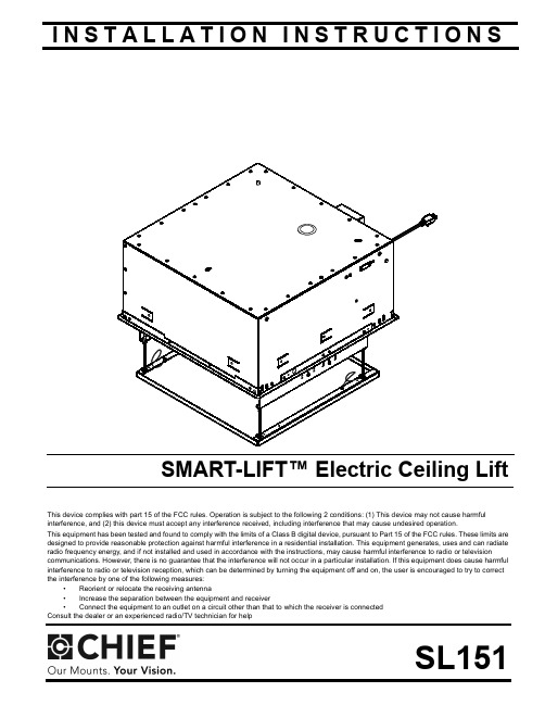
I N S T A L L A T I O N I N S T R U C T I O N SThis device complies with part 15 of the FCC rules. Operation is subject to the following 2 conditions: (1) This device may not cause harmful interference, and (2) this device must accept any interference received, including interference that may cause undesired operation.This equipment has been tested and found to comply with the limits of a Class B digital device, pursuant to Part 15 of the FCC rules. These limits are designed to provide reasonable protection against harmful interference in a residential installation. This equipment generates, uses and can radiate radio frequency energy, and if not installed and used in accordance with the instructions, may cause harmful interference to radio or televisioncommunications. However, there is no guarantee that the interference will not occur in a particular installation. If this equipment does cause harmful interference to radio or television reception, which can be determined by turning the equipment off and on, the user is encouraged to try to correct the interference by one of the following measures:•Reorient or relocate the receiving antenna •Increase the separation between the equipment and receiver •Connect the equipment to an outlet on a circuit other than that to which the receiver is connected Consult the dealer or an experienced radio/TV technician for helpSL151SMART-LIFT™ Electric Ceiling LiftSL151Installation Instructions2DISCLAIMERMilestone AV Technologies, and its affiliated corporations and subsidiaries (collectively, "Milestone"), intend to make thismanual accurate and complete. However, Milestone makes no claim that the information contained herein covers all details,conditions or variations, nor does it provide for every possible contingency in connection with the installation or use of this product. The information contained in this document is subject to change without notice or obligation of any kind. Milestone makes no representation of warranty, expressed or implied,regarding the information contained herein. Milestone assumes no responsibility for accuracy, completeness or sufficiency of the information contained in this document.Chief® is a registered trademark of Milestone AV Technologies.All rights reserved.IMPORTANT SAFETY INSTRUCTIONSWARNING alerts you to the possibility ofserious injury or death if you do not follow the instructions.CAUTIONalerts you to the possibility ofdamage or destruction of equipment if you do not follow thecorresponding instructions.WARNING :FAILURE TO READ ANDFOLLOW THE FOLLOWING INSTRUCTIONS CAN RESULT IN SERIOUS PERSONAL INJURY , DAMAGE TO EQUIPMENTOR VOIDING OF FACTORY WARRANTY . It is the installer’sresponsibility to make sure all components are properly assembled and installed using the instructions provided.IMPORTANT ! :Model SL151 is suitable for use in OtherEnvironmental Air Space in Accordance with Section 300.22(C)of the National Electrical Code.When using an electrical mounting system, basic precautionsshould always be followed, including the following:READ ALL INSTRUCTIONS BEFORE USING THISPRODUCTDANGER:TO REDUCE THE RISK OFELECTRIC SHOCK:1.Always turn off power at source before cleaning.WARNING:TO REDUCE THE RISK OFBURNS, FIRE, ELECTRIC SHOCK, OR INJURY TO PERSONS:•Always turn off power at source before putting on or taking off parts.•Use this mounting system only for its intended use as described in these instructions. Do NOT useattachments not recommended by the manufacturer.•Never operate this mounting system if it has a damaged test cord or test plug. If it is not working properly during testing, return the mounting system to a service center for examination and repair.•Keep the test power cord away from heated surfaces.•Never operate the mounting system with the airopenings blocked. Keep the air openings free of lint,hair, and the like.•Never drop or insert any object into any opening.•Do not use outdoors unless marked for outdoor use.•Route cords and cables as shown in the installation instructions.•To disconnect, turn all controls to the off position, then turn off power at source.WARNING :RISK OF ELECTRIC SHOCK!Connect this mounting system to a properly grounded outlet only. See Grounding Instructions.CAUTION:Changes or modifications to thisunit not expressly approved by the manufacturer can void the units FCC compliance rating and make the unit illegal to operate.WARNING :Failure to provide adequatestructural strength for this component can result in serious personal injury or damage to equipment! It is the installer’s responsibility to make sure the structure to which thiscomponent is attached can support five times the combined weight of all equipment. Reinforce the structure as required before installing the component.WARNING :Exceeding the weight capacitycan result in serious personal injury or damage to equipment! It is the installer’s responsibility to make sure the weight of all components attached to the SL151 does not exceed 35 lbs (15.9 kg).WARNING :RISK OF INJURY! Do not placevideo equipment such as televisions or computer monitors on the ceiling panel of the SL151.NOTE:This system has no user serviceable parts.--SAVE THESE INSTRUCTIONS--Installation Instructions SL1513TOOLS REQUIRED FOR INSTALLATIONPARTSLEGENDTighten FastenerApretar elemento de fijación Befestigungsteil festziehen Apertar fixador Serrare il fissaggio Bevestiging vastdraaien Serrez les fixations Loosen FastenerAflojar elemento de fijación Befestigungsteil lösen Desapertar fixador Allentare il fissaggio Bevestiging losdraaien Desserrez les fixationsPhillips Screwdriver Marcar con lápiz Stiftmarkierung Marcar com lápis Segno a matita Potloodmerkteken Marquage au crayon Adjust Ajustar Einstellen Ajustar Regolare Afstellen AjusterSL151Installation Instructions4DIMENSIONSTABLE OF CONTENTSDisclaimer.....................................................2Tools Required For Installation.................... 3Parts..............................................................3Legend..........................................................3Dimensions...................................................4Installation Requirements..............................5Power Requirements.....................................5Pre-test Lift Before Installation.......................5Power Requirements And Wiring...................5Grounding Instructions.................................. 6Removing Ceiling Panel................................ 6Installing in Ceiling.........................................6-Installing In A Suspended Ceiling...............6-Installing In A Wood Framework (Joists)....7Installing Projector On SL151 (7)Adjustments...................................................7Connecting Control Wiring.............................8Connecting To Power Supply.........................8Wiring Options............................................... 9Re-Attaching Ceiling Panel............................9Table 1: Wiring Table...................................10Table 2: Internal Terminal Descriptions........11Internal/External Wiring TerminalDescriptions (12)Installation Instructions SL1515Figure 25.Place the jumper wire (H) on the external wiring terminal contacts labeled 2and 5, and wire the push button assembly (D) to contacts 1 (red) and 6 (black). (See Figure 3).Figure 36.Plug in the SL151 test cord. (See Figure 2)NOTE:(See Figure 2) for location of external wiring terminal.(See Figure 4) for location of internal wiring terminal.Figure 4Power Requirements and WiringThe SL151 requires 120VAC, 60 Hz and 12 amps power to operate.IMPORTANT ! :This product must be grounded. If it shouldmalfunction or break down, grounding provides a path of least resistance for electric current to reduce the risk of electric shock.Grounding InstructionsThis product is equipped with a test cord having an equipment-grounding conductor and a grounding plug. The plug must be plugged into an appropriate outlet that is properly installed and grounded in accordance with all local codes and ordinances.Wire push button assembly (D) (1-red,6-black)[Some parts not shown for clarity]Internalwiring terminalSL151Installation Instructions6WARNING:RISK OF ELECTROCUTION! All electricalwiring required for installation should be installed by aqualified electrician.WARNING:PINCH HAZARD! FINGERS OR HANDSBETWEEN MOVING PARTS CAN LEAD TO SEVERE PERSONAL INJURY! Keep fingers and hands away from mount when operating.7.Press the push button to test the SL151 while it is still in the pre-test position.•Press when the lift is at its extended position and it willretract.•Press when the lift is at its retracted position and it willextend.•Press while the lift is moving and it will stop.•Leave SL151 in the open position.Removing Ceiling Panel1.Remove and save screws attaching guide wires to ceiling panel. (See Figure 5)Figure 52.Lift up on each corner of ceiling panel to remove pan from clips. (See Figure 6) and (See Figure 7)Figure 6Figure 7INSTALLING IN CEILINGWARNING:IMPROPER INSTALLATION CAN LEAD TOLIFT FALLING CAUSING SEVERE PERSONAL INJURY ORDAMAGE TO EQUIPMENT! It is the installers responsibility to make certain the structure to which the lift is beingmounted is capable of supporting five times the weight of the lift and all attached equipment. Reinforce the structure as required before installing the lift.NOTE:The following instructions assume a suitable mountingstructure and surface exists prior to installation and all power and signal wires and cables have been properly installed.Installing in a Suspended CeilingNOTE:The SL151 may be suspended from three 3/8 in.diameter x 8 in. length (minimum) Grade 2 or better threaded rods (not provided) which are secured to a 1-5/8" x 1-5/8" 12ga metal framing channel (spanning a maximum of 5 feet--not provided) by Grade 2 or better 3/8" channel nuts (not provided).1.Turn SL151 over and place onto threaded rods, inserting the rods into the three slots on top of the SL151 housing.(See Figure 8)2.Secure the threaded rods to the SL151 with Grade 2 or better 3/8 in. jam nuts (not provided) and washers (one of each on inside and one of each on outside-not provided).Figure 8Guide Wire(one on each side)Remove Screw (one on each side)Ceiling PanelGuide WireCeiling PanelClipCeiling Panel RemovedCAUTION:Avoid stressing or bending the lift during installation.e the provided push button (D) to operate the SL151 upand down, ensuring that all clearances are adequate. Installing Projector on SL151NOTE:bracket (a Listed accessory).1.Attach the SLB bracket to the projector following theinstructions included with the bracket.2.Attach the bracket with the projector to the SL151, adjustingleft or right by using the various attachment points in theSL151. (See Figure 10)•Adjust one or the other side of the bracket backward or forward by loosening two screws on each side. (SeeFigure 12)•Adjust bracket as required.•Tighten screws. (See Figure 12)78Unplug the SL151’s test cord (used for testing).Remove the jumper wire and supplied push button wiring (previously installed in the section) from the external terminal block. (See Figure 3)Connect control wiring following instructions included withthe controller and information in Table 1: Wiring Table NOTE:Any knockouts removed in the SL151 must bereplaced with a supplied rubber grommet (G).Feed the video and/or communications cables through theknockout in the rear or top of the lift and connect it to the projector.Ensure there is enough slack in the cables to allow forup and down movement of the lift.Secure cables as necessary using supplied mounting pads (E) and cable ties (B).CAUTION:KEEP SL151 OPEN WHILE PROJECTOR ISRUNNING OR IN COOLING MODE! Premature bulb failure or damage to electrical components may occur if lift closes.NOTE:If SL151 is cycled up and down repeatedly the motor’sthermal overload protection will stop operation.Operation will resume when the thermal overload resets (usually within 3 to 5 minutes).Connecting to Power SupplyIMPORTANT ! :This product must be connected to agrounded metal, permanent wiring system, or an equipment-grounding conductor must be run with the circuit conductors and connected to the equipment-grounding terminal or lead on the product.1.Disconnect and remove power inlet from interior junctionbox.2.Hardwire unit to a 120V 60Hz 12-amp power source.NOTE:This unit was designed to have conduit run directly intothe back of the interior junction box.WARNING:performed by a licensed electricianfollowing all local codes and ordinances.WARNING:DISCONNECT AND TERMINATE POWER LEADS PROPERLY MAY RESULT IN PERSONAL INJURY OR EQUIPMENT DAMAGE!! Licensed electrician must disconnect and terminate the leads to the power cord receptacle, and must hard wire the SL151 to a 12-amp power source.CAUTION:not lined up properly with rectangular holes.Figure 142.Carefully insert clips into rectangular holes in ceiling panel.3.Reattach guide wires (two places) to ceiling panel, usingscrews removed earlier. (See Figure 15)9SL151Installation Instructions10Table 1: WIRING TABLEFigure 16NOTE:The numbers listed in the SL151 Internal and SL151 External columns refer to the corresponding numbers located whereindicated in the wiring pictures. (See Figure 16)EXTERNAL WIRINGINTERNAL WIRINGTable 2: INTERNALTERMINAL DESCRIPTIONS1112Figure 17131415Chief Manufacturing, a products division of Milestone AV Technologies8820-000041 Rev022010 Milestone AV Technologies, a Duchossois Group Company04/10USA/International A8401 Eagle Creek Parkway, Savage, MN 55378P800.582.6480 / 952.894.6280F877.894.6918 / 952.894.6918Europe A Fellenoord 130 5611 ZB EINDHOVEN, The NetherlandsP+31 (0)40 2668620F+31 (0)40 2668615Asia Pacific A Office No. 1 on 12/F, Shatin Galleria18-24 Shan Mei StreetFotan, Shatin, Hong KongP852 2145 4099F852 2145 4477。
加密方案是无条件安全的。但是除非是一次一密(one产品
河海大学硕士学位论文于2E移动支付安基JM的全方案研究与实践果由一个加密方案产生的密文中包含的信息不足以惟一决定文,对应的明则称此加密无条方案是件安全的。
但是除非是一次一密(nte)oeipd方案,-am实际中是没有无条件安全的加密算法的W因加密.此,算法的户所能。
用做的就是满足下列准则中的一个或两个:一个是破译该密码的成本超过被加密信息的价值;另一个是破译该密码的时间超过该信息有用的生命周期。
.22.1.3可用性和互操作性问题,除了安全性可用性也非常关键。
也就是移动支付服务是否易于使用以及使用所带来的用户体验的好坏也是影响移动支付发展的一个重要因素门。
由于现有的用户终端设备的硬件条件,移动通信网络所采用的协议都有相当大的局限性,在可用性设计的方面仍有许多限制。
由于移动支付必须要在移动终端设备上进行操作,而像手机等移动终端设备在色屏幕大小、彩表现力、芯片键盘、处理能力、内存大小等硬件配置方面都是有限的,此外还要受到无线网络的带宽和延时问题的影响,这就决定了移动设备不C可能像P机一样提供给用户很好的用户体冈验或易用性。
另外,互操作问题也不仅仅局限于用户终端,还包括用户在支付时直接打交机、O机、自道的收款PS动贩售机等等,这些都需要制定一些行业标准,与相关行业企业达成共识。
13现有研究关键技术.现在国内外对于移动支付的安全研究比多,也提出了许多安全方案。
较20年,AioriHlae等人提出了一种称为WS’ 102atealFua.lKflI” E{的方法。
它结E和TSS优势,T合了STWL/L的加强了AL的基于WPO移动支付系统的安全性。
它E使用ST协议的三个方面:永久签名保证完整性:提供端到端交易网关证书:被支付者对交易进行确认。
外也另TSL协议的T使用了WL/S两个方面:安全参数商定和支付者与被支付者的证明。
这样使得有用数据与加密数据分离,保障了端到端的机密性:也能防止被支付者的击。
也避免了重放攻同时移动环境E的注册和下ST验证过程太繁重,使?煌 耐ㄑ恫棵?可以L证书使用相同的TS进行各种操作。
官方PCTI考试题
PCTI认证考试模拟题一、选择题(单选,35题,每题2分)1. HTML 的主体内容放在:()A. <head〉.。
</head> 中间B. 〈title>。
.。
〈/title> 中间C。
<body>。
</body> 中间D. 〈form〉。
.〈/form> 中间2。
以下哪种语句是实现表单提交的动作()A。
〈input type=submit name=**〉B. 〈input type=reset name=**〉C。
〈input type=text name=**>D。
<input type=password name=**>3. 以下哪种类型是B/S构架的正确描述()A. 需要安装客户端的软件B. 不需要安装就可以使用的软件C. 依托IE浏览器的邮件系统D. 依托outlook等软件的邮件系统4. 以下哪种表达方式是错误的()A. <form action=”url” method=*target=#> 〈/form〉B. 〈input type=submit>〈/input>C。
<select name=*〉〈option value=*selected〉。
</select〉D。
〈html〉〈head〉〈title></title>〈/head>〈/html>5。
以下哪种提交方式是隐藏提交()A. type = hiddenB。
type = textC. type = passwordD。
type = checkbox6。
以下对于CSS的表达哪个是错误的()A。
可以将CSS的代码保存在其它文件中,在需要时调用比如〈link href=”text/text.css” rel=”stylesheet" type=”text/css"> B. 可以把CSS的代码直接写在HTML中〈style type=”text/css”>〈!-- .类名{属性。
纹理物体缺陷的视觉检测算法研究--优秀毕业论文
摘 要
在竞争激烈的工业自动化生产过程中,机器视觉对产品质量的把关起着举足 轻重的作用,机器视觉在缺陷检测技术方面的应用也逐渐普遍起来。与常规的检 测技术相比,自动化的视觉检测系统更加经济、快捷、高效与 安全。纹理物体在 工业生产中广泛存在,像用于半导体装配和封装底板和发光二极管,现代 化电子 系统中的印制电路板,以及纺织行业中的布匹和织物等都可认为是含有纹理特征 的物体。本论文主要致力于纹理物体的缺陷检测技术研究,为纹理物体的自动化 检测提供高效而可靠的检测算法。 纹理是描述图像内容的重要特征,纹理分析也已经被成功的应用与纹理分割 和纹理分类当中。本研究提出了一种基于纹理分析技术和参考比较方式的缺陷检 测算法。这种算法能容忍物体变形引起的图像配准误差,对纹理的影响也具有鲁 棒性。本算法旨在为检测出的缺陷区域提供丰富而重要的物理意义,如缺陷区域 的大小、形状、亮度对比度及空间分布等。同时,在参考图像可行的情况下,本 算法可用于同质纹理物体和非同质纹理物体的检测,对非纹理物体 的检测也可取 得不错的效果。 在整个检测过程中,我们采用了可调控金字塔的纹理分析和重构技术。与传 统的小波纹理分析技术不同,我们在小波域中加入处理物体变形和纹理影响的容 忍度控制算法,来实现容忍物体变形和对纹理影响鲁棒的目的。最后可调控金字 塔的重构保证了缺陷区域物理意义恢复的准确性。实验阶段,我们检测了一系列 具有实际应用价值的图像。实验结果表明 本文提出的纹理物体缺陷检测算法具有 高效性和易于实现性。 关键字: 缺陷检测;纹理;物体变形;可调控金字塔;重构
Keywords: defect detection, texture, object distortion, steerable pyramid, reconstruction
II
PFUlimited 2022年版FI-8150扫描仪说明书
E ciency optimized, simplicity achie v ed, with expanded software functionalities The scanner driver, PaperStream IP, comes with a simplified, user-friendly interface thatprovides icon visibility for easy setting config-urations. Users can consistently achieve scanned outputs of correct orientations withthe "Automatic Rotation" function, and store frequently scanned documents in specific formats using the "pattern matching" method.Efficiency with simplification brings users, a reduction to operation time as well on frequent and routine operations like deleting blank pages, or correcting page orientations, just by following the optimal settings suggest-ed by the “Settings Assistant” on the integrat-ed PaperStream Capture software. Documents can be retrieved more efficiently with the "PDFkeyword setting" function, instead of being constrained to file names alone.Optimized high-quality imagesThe fi-8150 comes with “Clear Image Capture”, a unique and dedicated image correction technology that generates unparalleled, high-definition images while keeping power consumption to the minimum. Quality images with no missing edges can be ensured with the scanner’s Skew Reducer mechanism.Better usability and exibility for any environ-mentThe fi-8150 supports multiple operation modes according to users’ environments, may that require sharing among teams with PC-less colleagues, or LAN connectivity and USB 3.2.The flexibility to use with imprinter options opens up the capability for total document management and assists in documentarchiving requirements that are prevalent in many industries. Reliable. State-of-art feeding and optical technologies.Quality images. The best you can get.Paper handling. Scan with confidence.State-of-art feeding technology - streamline work owIn the “Manual Feed Mode”, the fi-8150 scanscopy forms and passports or booklets up to thicknesses of 7 mm with the carrier sheet. Precise multi-feed detection on a wide range of documents like plastic cards and documents with attachments, enable contin-ual scanning with the same profiles. In addition, the “Automatic Separation Control” optimizes paper feed to match the number of sheets loaded, preventing interruptions. “Image Monitoring” also performs checks, real-time, for image skews, and providesenhanced paper protection.Efficiency at new heights with evolved feedingDatasheetFUJITSU Image Scanner fi-8150Datasheet FUJITSU Image Scanner fi-8150ContactTrademarksISIS is a trademark of Open Text. Microsoft, Windows, and Windows Server are either registered trademarks or trademarks of Microsoft Corporation in the United States and/or other countries. macOS is a trademark of Apple Inc., registered in the U.S. and other countries. Linux is the registered trademark of Linus Torvalds in the U.S. and other countries. Any other products or company names appearing in this document are the trademarks or registered trademarks of the respective companies.Safety PrecautionsPlease carefully read the safety precautions prior to the use of this device and follow the recommended instructions for correct use. Do not place this device in wet, moist, highly humid, dusty or oily areas. Use of this device under such conditions may result in electrical shock, fire or damage to the device. Please use this device within the power ratings listed.ENERGY STAR®PFU Limited, a Fujitsu company, has determined that this product meets the ENERGY STAR® guidelines for energy efficiency. ENERGY STAR® is a registered trademark of the United States.Specifications are subject to change without notice. Visit your local Fujitsu website for more information.*1 Actual scanning speeds may vary with data transmission and software processing times. *2 Indicated speeds are from using JPEG compression. *3 Indicated speeds are from using TIFF CCITT Group 4 compression.*4 Selectable maximum resolution may vary depending on the length of the scanned document. *5 Limitations may apply to the size of documents that can be scanned, depending on system environment, when scanning at high resolution (over 600 dpi). *6 Maximum document width possible for scanning is 240 mm (9.5 inch). *7 For use with PaperStream NX Manager, the maximum resolution supported is 400 dpi, with maximum lengths ranging with resolution. Simplex: 1,828.8 mm (72 in.) [below 300 dpi], 355.6 mm (14 in.) [below 400 dpi]. Duplex: 863.6 mm (34 in.) [below 300 dpi], 355.6 mm (14 in.) [below 400 dpi]. *8 Thicknesses of up to 128 to 209 g/m² (34 to 56 lb) can be scanned for A8 (52 x 74 mm / 2.1 x 2.9 inch) sizes. *9 Booklet scanning requires use of Booklet Carrier Sheets. Indicated thickness is inclusive of Booklet Carrier Sheet thickness. *10 Continuous feeding is supported when scanning up to 10 unembossed cards with thicknesses of 0.76 mm or less. *11 Maximum capacity depends on paper weight and may vary. *12 Capable of setting additional documents while scanning. *13 Numbers are calculated using scanning speeds and typical hours of scanner use, and are not meant to guarantee daily volume or unit durability. *14 Excludes the ADF paper chute and stacker. *15 Functions equivalent to those offered by PaperStream IP may not be available with the Image Scanner Driver for macOS/Linux or WIA Driver. *16 Refer to the fi Series Support Site for driver/software downloads and full lineup of all supported operating system versions. https:///global/support/products/computing/peripheral/scanners/fi/.4,000,000 printed characters or 6 months after opening the packageCA00050-0262Print CartridgeEvery 200,000 sheets or one year PA03670-0002Pick Roller Every 200,000 sheets or one year PA03810-0001Brake Roller ConsumablesPaperStream Capture Pro optional licensePA43404-A665PaperStream Capture Pro Scan Station (WG)Reads PDF417, QR code, Data Matrix, Aztec CodePA43404-A4332D Barcode for PaperStreamPack of single sheetPA03810-0020Booklet Carrier Sheet Pack of 3 sheets PA03770-0015 Photo Carrier Sheets Pack of 5 sheets PA03360-0013 Carrier Sheets Prints on the back of the document PA03810-D201 Post Imprinter (FI-819PRB) OptionsADF paper chute, AC cable, AC adapter, USB cable, Setup DVD-ROMIncluded ItemsMulti image output, Automatic color detection, Blank page detection, Dynamic threshold (iDTC), Advanced DTC, SDTC,Error diffusion, Dither, De-Screen, Emphasis, Dropout color (None/Red/Green/Blue/White/Saturation/Custom), sRGBoutput, Hole punch removal, Index tab cropping, Split image,De-Skew, Edge filler, Vertical streaks reduction, Background pattern removal, Cropping, Static thresholdImage Processing FunctionsPaperStream IP Driver (TWAIN/TWAIN x64/ISIS), WIA Driver *¹⁵, Image Scanner Driver for macOS (ICA)*¹⁵*¹⁶, Image Scanner Driver for Linux (SANE)*¹⁵*¹⁶, PaperStream Capture,PaperStream ClickScan *¹⁶, Software Operation Panel, Error Recovery Guide, ABBYY FineReader for ScanSnap™*16, Scanner Central AdminIncluded Software / DriversWindows® 11, Windows® 10, Windows® 8.1, Windows® 7, Windows Server® 2022, Windows Server® 2019, Windows Server® 2016, Windows Server® 2012 R2, Windows Server® 2012, Windows Server® 2008 R2, macOS, Linux (Ubuntu)Supported Operating System4 kg (8.8 lb)Weight300 x 170 x 163 mm (11.8 x 6.7 x 6.4 inch )Dimensions *¹⁴(Width x Depth x Height)ENERGY STAR®, RoHSEnvironmental Compliance 15 to 80% (non-condensing)Relative Humidity5 to 35 °C (41 to 95 °F)Temperature Operating Environment 0.2 W or lessAuto Standby (Off) Mode 2.0 W or less (LAN) / 1.4 W or less (USB)Sleep Mode21 W or less / 17 W (Eco mode)Operating Mode Power Consumption AC 100V - 240V 50/60 Hz Power Requirements 10BASE-T, 100BASE-TX, 1000BASE-T EthernetUSB 3.2 Gen1x1 / USB 2.0 / USB 1.1USB Interface Image monitoringPaper Protection Overlap detection (Ultrasonic sensor), Length detection Multifeed Detection 8,000 sheetsExpected Daily Volume *¹³100 sheets (A4 80 g/m² or Letter 20 lb)ADF Capacity *¹¹*¹²Less than 7 mm (0.276 inch )*⁹20 to 465 g/m² (5.3 to 124 lb)*⁸Plastic Card 1.4 mm (0.055 inch ) or less *¹⁰Booklet Paper Paper Weight (Thickness)6,096 mm (240 inch )Long Page Scanning *⁷48 x 50 mm (1.9 x 2 inch)Minimum215.9 x 355.6 mm (8.5 x 14 inch)Maximum *⁶Document Size White / Black (selectable)Background Colors Color: 24-bit, Grayscale: 8-bit, Monochrome: 1-bit Output Format 50 to 600 dpi (adjustable by 1 dpi increments),1,200 dpi (driver)*⁵Output Resolution *⁴(Color / Grayscale / Monochrome)600 dpiOptical ResolutionRGB LED x 2 (front x 1, back x 1)Light Source CIS x 2 (front x 1, back x 1)Image Sensor Type Simplex: 50 ppm (200/300 dpi)Duplex: 100 ipm (200/300 dpi)Scanning Speed *¹ (A4 Portrait)(Color *²/Grayscale *²/Monochrome *³)ADF (Automatic Document Feeder) / Manual Feed, DuplexScanner TypeTechnical InformationDatasheet FUJITSU Image Scanner fi-8150IndonesiaPT Fujitsu Indonesia Tel: +62 21 570 9330*************************/id/scannersMalaysiaFujitsu (Malaysia) Sdn Bhd Tel: +603 8230 4188askfujitsu .my @/my/scannersPhilippinesFujitsu Philippines, Inc. Tel: +63 2 841 8488 ***************.com/ph/scannersSingaporeFujitsu Asia Pte Ltd Tel: +65 6512 7555 *******************/sg/scannersThailandFujitsu (Thailand) Co., Ltd. Tel: +66 2 302 1500 info .th @/th/en/scannersVietnamFujitsu Vietnam Limited Tel: + 84 4 2220 3113 sales -vn @/vn/en/scanners。
- 1、下载文档前请自行甄别文档内容的完整性,平台不提供额外的编辑、内容补充、找答案等附加服务。
- 2、"仅部分预览"的文档,不可在线预览部分如存在完整性等问题,可反馈申请退款(可完整预览的文档不适用该条件!)。
- 3、如文档侵犯您的权益,请联系客服反馈,我们会尽快为您处理(人工客服工作时间:9:00-18:30)。
1
Introduction
CDMA has been recognised as an important access scheme for third generation mobile radio communication systems [1]. However, the attractive flexibility of CDMA comes at the price of multiple access interference (MAI) and also intersymbol interference (ISI) which is magnified in the mobile radio channel where time varying multipath propagation is present [1]. ISI and, more importantly, MAI can be mitigated by multiuser detection techniques, [2]–[8], which are also termed joint detection (JD) techniques [9, 10]. Unfortunately the optimum
Abstract In this paper we align a class of known multiuser detectors for code division multiple access (CDMA) along with some new multiuser detectors in a unified group. The new multiuser detectors are devised by completing the structure of the group. The unified group structure is a binary tree obtained by splitting • sequence and single symbol detection, • maximum a–posteriori (MAP) and maximum likelihood (ML) detection, and • unconstrained as well as constrained detection. The link between sequence and single symbol estimators is explained revealing the increased complexity of single symbol estimators as compared to sequence estimators. Finally, the aforementioned group structure is supported by a geometrical technique depicting the detection process performed by the multiuser detectors.
Page 1
A Unified Approach to Multiuser Detectors for CDMA and Their Geometrical Interpretations
Peter Jung
University of Kaiserslautern Department of Electrical Engineering Research Group for RF Communications P.O. Box 3049 D–67653 Kaiserslautern, Germany E-Mail: wowbag@rhrk.uni-kl.de
Paul D. Alexander
University of South Australia Signal Processing Research Institute Mobile Communications Research Centre Warrendi Road, The Levels SA 5095, Australia E-Mail: palex@.au
P. Jung, P. D. Alexander: A Unified Approach to Multiuser Detectors for CDMA and Their Geometrical Interpretations
Page 2
multiuser detectors (MD’s) for both sequence detection (SD) and single symbol detection (SSD) are not practical due to the performance/cost ratio exhibited by today’s technology. To alleviate this complexity problem many linear complexity MD’s have been proposed in the literature, cf. e.g. [3], [7]–[11]. These MD’s trade performance for complexity and thus become candidates for implementation in third generation mobile radio systems [1]. The viability of such linear complexity MD’s has already been demonstrated in a recently proposed cellular CDMA mobile radio system applying JD which is termed JD–CDMA [10, 12]. The optimum and linear complexity MD’s have been developed independently and the similarities between them have not been illustrated yet. This shall be done in this paper. Moreover, we shall give an illustrative geometrical description of the detection process carried out by the aforementioned MD’s. To allow a better understanding of the following explanations, we shall first give a definition of the terms detection and estimation. An elaborate presentation of estimation and detection theory can be found in [13]. Detection is the deciding on the cause of an output that is random in character, based on the observation of the mentioned output. For example, the cause could be a data symbol transmitted over a radio channel, resulting in a particular output signal after the channel. This output signal represents the aforementioned observation. Assume that the symbol alphabet has cardinality M . The symbol alphabet is therefore a constrained set. There are M different possible causes that might have resulted in the observation. Hence, the detection outcome is a random variable taken from a constrained set, which is identical to the symbol alphabet. The detection outcome is hence M –ary. Estimation is the determining of the value of a parameter which has influenced the aforementioned observation. The estimation outcome is hence not constrained to a set with finite cardinality. It is rather taken from an unconstrained set. Estimation is hence the continuous extension of detection. In what follows, we will use the term detection in most cases, however, being well aware of the fact that detectors can also be seen as estimators. Two categories of MD’s are conceivable, namely SD based MD’s and SSD based MD’s. In the case of the SD based MD’s the objective is to find that particular data sequence which was most probably transmitted according to some hypothesis criterion. SSD based MD’s try to find that particular data symbol which was most probably transmitted at a particular time, again satisfying some hypothesis criterion. SSD based MD’s are not widely known and to the knowledge of the authors have not yet been studied thoroughly. The authors shall concisely explain the basis of such rather new SSD based MD’s and shall also demonstrate