德国倍加福超声波传感器UC6000-30GM
ULTRAPROBE 2000 灵活 易适应的超声波检测仪说明书

ULTRAPROBE ®2000re-sponse for enhanced leak and fault detection.2) Linear Mode provides a slow, averaging response to stabilize readings for bearing and mechanical monitoring.A 10-turn Sensitivity Adjust Dialprovides a wide dynamic sensitivity range.Trisonic ™ Scanning Modulea patented transducer, consists of a phased array of three transducers, which provides a level of sensitivity beyond anything previously obtainable.Acoustic Headphones:• Noise isolating type for loud environments.Intrinsically Safe:• FM, CSA, ATEX ratedThe ultimate analog ultrasonic inspectionsystem for predictive maintenancePressure & Vacuum Leak Detection Hydraulic Valve Bypass Exhaust System LeaksHeat Exchangers, Boilers, Condensers Valve & Steam Trap Inspection Bearing TestingGear/Gear Box Inspection Tanks, Pipes, Leak Testing, etc.Electrical Inspection••••••••••••••••••• ••••••••APPLICATION KIT # UP2000KT U P2000SC U P2000C U P2000SStethoscope moduleLong range moduleClose focus moduleUltrasonic CD Training Series is IncludedThis professionally produced series was shot in actual plant environments enabling you to see, hear and experience realistic test examples along with practical solu-tions. The training series is applicable for all levels of ultrasonic testing experience and is arranged in an organized format. You’ll be taken step by step through each application. The following sections are included in the CD's:• Introduction to Airborne Ultrasound • Review of each Ultraprobe Feature • O verview of the Specific Application (Leak Detection, Mechanical andBearing Inspection, Heat Exchangers, Boilers & Condensers, Steam Traps & Valves, Electrical Inspection)• Demonstration of Testing Techniques • Problem Solving TechniquesConstruction Circuitry Frequency ResponseProbesTransmitter HeadsetIndicatorsBattery FeaturesOverall SizeSensitivity Threshold*Warranty Display ModesHand-held metered pistol type made with aluminum and ABS plasticSolid State heterodyne receiver with temperature compensation Frequency Detect ultrasonic frequencies between 20 kHz and 100 kHz, continuously variableFrequencies are converted to 50 kHz to 3 kHz audioScanning Module patented Trisonic plug-in type consisting of a phased array of multiple transducers for airborne ultrasound. This probe is shielded against RF interference.Rubber Focusing Probe (flexible) slips over scanning module to concentrate conical directivity and to shield reception of stray ultrasound. Also fits over Stethoscope Module to shield against high ambient ultrasound while unit isat maximum sensitivity.Stethoscope Module – plug-in type, insulated probe with RF shielding; 11.4 cm (4 1/2”) long stainless steel probe tip, conically shaped for uniform surface contact. Stethoscope Extension Kit: 3-piece, segmented metal rods to increasestethoscope contact range for 50.8 cm (20”) and 76.2 cm (31”).Patented warble tone transmissionNoise isolating type: Double headset wired monophonic. Impedance16 ohms. Over 23 dB of noise attenuation.Meets or exceeds ANSI specifications and OSHA standards. For hard hat use.Ballistic output meter; linear calibration scale of 0-100 for logging relative measurements. Meter is accurate 1% throughout entire scale. Low Level Battery LED indicator for main housing internal power supply.Self contained NiMH rechargeable.RECHARGING SYSTEM: Standard 110V . Also available in 220V .Frequency Tuning Adjustment Dial: 20-100 kHz with "fixed band" position for ultra-narrow frequency response.Bi-Modal Meter Switchfor logarithmic and linear meter scale adjustments.Optional Auxiliary Modeselection for chart recorder output: 0-50 mV .Sensitivity Control – Precision 10-turn adjustment dial with numerically calibrated sensitivity increments for finite gain adjustment.Spring loaded trigger switchComplete kit in Zero Halliburton aluminum carrying case:47 x 37 x 17 cm (18.5” x 14.5” x 6.5”)Pistol unit: 0.9 kg (2 lbs.)Complete carrying case: 6.4 kg (14 lbs.)Detects0.127mm(0.005")********************(5psi) at a distance of 15.24 m (50 ft.)1 x 10⁻² std. cc/sec to 1 x 10⁻³ std. cc/sec 1-year parts/labor standard,5 years with completed warranty registration card.Logaritmic and linear*depends on leak configuration**specify Ex rating if needed at time of orderUltraprobe ® 2000 SpecificationsUltraprobe 2000 Kit: Meets and exceeds ASTM E1002-2005 requirements for Leak Detection. Government Codes NSN: 6635-01-156-3927, FSCM (CAGE) Code: 59202. Table of allowance #s: 788, 404, 576, 583, 607. Covered by one or more of the following patents: 0151115; 0303776; 0315199; 1206586; 1297576; 1881263; 2562758; 2689339; 4416145; 4823600; 5955670; 6122966; 6339961; 6341518; 6415645; 6655214; 6707762; 6804992 UE Systems is committed to continual product improvement; therefore specifications are subject to change without notice. Warranty details are available by request.Kit includes:• F requency Selection (20 kHz – 100 kHz)• Precision edgewise meter • 3-way meter/auxiliary mode selector • N umerically calibrated 10-turn sensitivity dial • R echargeable battery with lowlevel indicator light• Anodized aluminum housing • Trisonic™ Scanning Module • Stethoscope/Contact Module • Stethoscope Extension Kit • Rubber Focusing Probe • Warble Tone Generator• Deluxe noise isolating headset • Z ero Halliburton aluminium carrying case • I nstruction Manual andMultimedia Training**UE Systems Europe • Windmolen 22 • 7609 NN Almelo • The NetherlandsT: +31(0)548-659011 • F: +31(0)548-659010 • E:*****************• www.uesystems.euwww.uesystems.eu。
岸边集装箱起重机防撞系统分析与研究
• 56•随着岸桥大型化,智能化的发展,其防撞系统也需要不断升级。
本文对各种常规岸桥防撞系统进行分析研究,详细介绍了激光扫描传感器的在岸桥防撞系统的应用。
岸边集装箱起重机(以下简称岸桥)防撞系统包括大梁防撞系统和大车防撞系统。
功能是在大车运行过程中,保护大梁机构和大车机构不与障碍物碰撞。
随着船舶和岸桥大型化的发展,大梁和大车车道数量不断增加,船桅杆或雷达越来越高,同时作业的船舶、集卡数量越来越多,碰撞风险都大大增加。
而司机在司机室很难准确判断障碍物情况,就需要岸桥防撞系统发挥作用,避免碰撞事故。
岸桥防撞系统在不断发展升级,从机械、感应限位发展到激光扫描传感器(以下简称激光限位),防撞性能不断提高。
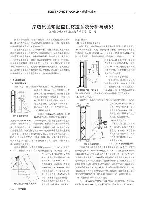
1 大梁防撞系统1.1 采用防撞钢丝如图1所示,前大梁两侧安装防撞钢丝,与大梁外侧面平行,满足安全要求。
1.2.1 大梁上平面斜角度安装如图2所示,激光限位安装在大梁中部上平面,大梁下平面以下0.8m 为保护拖令、拖链、滑触线等相关机构,同时根据激光限位安装高度1.1m 和大梁高度1.8m ,以及上面计算得出的8m 和4m 的减速、停止距离,计算出激光限位的安装角度,角度θ≈47.23°,同岸边集装箱起重机防撞系统分析与研究上海振华重工(集团)股份有限公司 梁 明图1 大梁防撞钢丝两者间距1896mm ,当大车运行时,防撞钢丝碰到了障碍物后,端部张紧架的弹簧会带动限位挡块动作,岸桥电控PLC 接受到限位信号后停止大车运行,避免大梁碰撞。
优点是安装调试简单;缺点是保护距离太短,没有减速功能。
1.2 采用激光限位常规采用SICK 品牌的LMS511-11100Lite 的激光限位,扫描角度可达到190°,测量有效距离0.5m-80m 。
工作原理是利用发出激光通过按一定速率旋转的三棱镜折射形成一个扇形面域,根据需要设置面域的保护区域,当有障碍物时,系统检测到激光能量发生衰减后输出信号可以由高电平直流24V 变为低电平直流0V (也可以软件设置由低电平变为高电平)。
倍加福接近传感器NCB4-12GM40-N0-V1电感式传感器
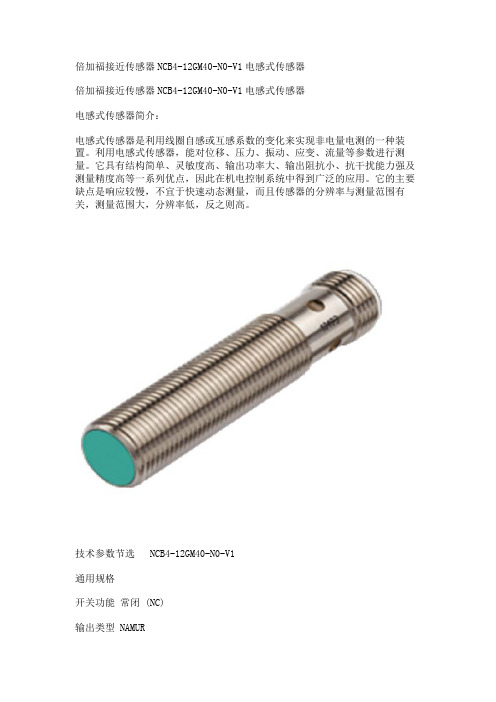
倍加福接近传感器NCB4-12GM40-N0-V1电感式传感器倍加福接近传感器NCB4-12GM40-N0-V1电感式传感器电感式传感器简介:电感式传感器是利用线圈自感或互感系数的变化来实现非电量电测的一种装置。
利用电感式传感器,能对位移、压力、振动、应变、流量等参数进行测量。
它具有结构简单、灵敏度高、输出功率大、输出阻抗小、抗干扰能力强及测量精度高等一系列优点,因此在机电控制系统中得到广泛的应用。
它的主要缺点是响应较慢,不宜于快速动态测量,而且传感器的分辨率与测量范围有关,测量范围大,分辨率低,反之则高。
技术参数节选 NCB4-12GM40-N0-V1通用规格开关功能常闭 (NC)输出类型 NAMUR额定工作距离 4 mm安装齐平确保操作距离 0 ... 3,24 mm实际工作距离 3,6 ... 4,4 mm 类型衰减系数 rAl 0,41衰减系数 rCu 0,39衰减系数 r304 0,78输出类型 2 线额定值额定电压 8,2 V (Ri 约 1 kΩ)开关频率 0 ... 1500 Hz迟滞 1 ... 15 类型 5 %反极性保护反极性保护短路保护是适用于 2:1 技术是,无需反极性保护二极管电流消耗未检测到测量板 min. 2,2 mA检测到测量板≤ 1 mA开关状态指示灯黄色多孔 LED功能性安全相关参数安全完整性级别 (SIL) SIL 2MTTFd 3010 a任务时间 (TM) 20 a诊断覆盖率 (DC) 0 %装置应用传感器作为采集和获取信息的工具,对系统的自动化检测和质量监测起着重要作用。
电感式传感器是一种互感式电感传感器,它可将微小的机械量,如位移、振动、压力造成的长度、内径、外径、不平行度、不垂直度、偏心、椭圆度等非电量物理量的几何变化转换为电信号的微小变化,转化为电参数进行测量,是一种灵敏度较高的传感器,具有结构简单可靠、输出功率大、抗阻抗能力强、对工作环境要求不高、稳定性好等一系列优点,因而被广泛应用于各种工程物理量检测与自动控制系统中 [3] 。
Pepperl+Fuchs UC4000-30GM-IUR2-V15 超声传感器产品说明书
UC4000-30GM-IUR2-V15Ultrasonic sensorUC4000-30GM-IUR2-V15R e l e a s e d a t e : 2018-01-08 10:27D a t e o f i s s u e : 2018-01-09104094_e n g .x m lDimensionsElectrical ConnectionPinoutTemperature probeCoded plug52225128ø40M30x1.527.536LEDStandard symbol/Connection:(v ersion IU)Sync.Core colors in accordance with EN 60947-5-2.0-10 V 4-20 mA + U B - U B15432(BN)(GY)(BK)(BU)(WH)U134521 BN2 WH3 BU4 BK 5GYWire colors in accordance with EN 60947-5-2(brown)(white)(blue)(black)(gray)Additional Information Analogue output functionNear distance of evaluation Far distance of evaluationAnalog functionRising slopeFalling slopeZero line mode20 mA/10 V4 mA/0 V4 mA/0 V 20 mA/10 V20 mA/10 V4 mA/0 VA1= 0 mmA2R e l e a s e d a t e : 2018-01-08 10:27D a t e o f i s s u e : 2018-01-09104094_e n g .x m l Description of Sensor FunctionsProgramming procedureThe sensor features 2 programmable analog outputs with programmable evaluation range. Programming the evaluation range and the operating mode is done either via the sensor's RS232 interface and ULTRA3000 software (see the ULTRA3000 software description) or by means of the programming plug at the sensor's back end which is described here.Programming of Evaluation Range1.Disconnect supply voltage2.Remove the programming plug to activate program mode.3.Reconnect supply voltage (Reset)4.Place the target at the desired position for A15.Momentarily insert the programming plug in position A1 and then remove. This will program the position A1.6.Place the target at the desired position for A27.Momentarily insert the programming plug in position A2 and then remove. This will program the position A2.Notes:•Removing the programming plug saves the new position into the device memory.•The programming status is indicated by the LED. A flashing green LED indicates that the target is detected; a flashing red LED indicates that no target is detected.Programming the Operation ModeIf the program mode is still activated, continue at number 4. If not, activate program mode by performing the sequence numbers 1 to 3.1.Disconnect supply voltage2.Remove the programming plug to activate program mode.3.Reconnect supply voltage (Reset)4.Insert the programming plug in position E2/E3. By removing and reinserting the plug, the user can toggle through the three different modes of operation. The selected mode is indicated by the LEDs as shown below:•Rising slope mode, LED A2 flashes •Falling slope mode, LED A1 flashes •Zero line mode, LEDs A1 and A2 flash5.Once the desired mode is selected, insert the programming plug in position T. This completes the programming procedure and saves the switch points and mode of operation.6.The sensor now operates in normal mode.Note:The programming plug also functions as the temperature compensation. If the programming plug has not been inserted in the T position within 5minutes, the sensor will return to normal operating mode with the latest saved values, without temperature compensation.Factory settings See technical data.DisplayThe sensor provides LEDs to indicate various conditions.Mounting flange, 30 mmBF 30-FMounting flange with dead stop, 30 mm UC-30GM-PROGULTRA3000Software for ultrasonic sensors, comfort line UC-30GM-R2DA5-IU-2K-VProcess control and indication equipment V15-G-2M-PVCFemale cordset, M12, 5-pin, PVC cableA2R e l e a s e d a t e : 2018-01-08 10:27D a t e o f i s s u e : 2018-01-09104094_e n g .x m lSynchronizationThis sensor features a synchronization input for suppressing ultrasonic mutual interference ("cross talk"). If this input is not connected, the sensor will operate using internally generated clock pulses. It can be synchronized by applying an external square wave. The pulse duration must be ≥100 µs. Each falling edge of the synchronization pulse triggers transmission of a single ultrasonic pulse. If the synchronization signal remains low for ≥ 1 second, the sensor will revert to normal operating mode. Normal operating mode can also be activated by opening the signal connection to the synchronization input (see note below).If the synchronization input goes to a high level for > 1 second, the sensor will switch to standby mode, indicated by the green LED. In this mode,the outputs will remain in the last valid output state.Note:If the option for synchronization is not used, the synchronization input has to be connected to ground (0 V) or the sensor must be operated via a V1 cordset (4-pin).The synchronization function cannot be activated during programming mode and vice versa.The following synchronization modes are possible:1.Several sensors (max. number see technical data) can be synchronized together by interconnecting their respective synchronization inputs.In this case, each sensor alternately transmits ultrasonic pulses in a self multiplexing mode. No two sensors will transmit pulses at the same time (see note below).2.Multiple sensors can be controlled by the same external synchronization signal. In this mode the sensors are triggered in parallel and are syn-chronized by a common external synchronization pulse.3.A separate synchronization pulse can be sent to each individual sensor. In this mode the sensors operate in external multiplex mode (see notebelow).4.A high level (+U B ) on the synchronization input switches the sensor to standby mode.Note:Sensor response times will increase proportionally to the number of sensors that are in the synchronization string. This is a result of the multiplex-ing of the ultrasonic transmit and receive signal and the resulting increase in the measurement cycle time.Note on communication with the UC-30GM-R2 interface cableThe UC-30GM-R2 interface cable allows for communication with the ultrasonic sensor using ULTRA3000 software. The cable creates a connection between a PC RS-232 interface and the programming plug socket on the sensor. When connecting to the sensor, make certain the plug is lined up correctly; otherwise no communication will be possible. The key of the cable’s plug must be aligned to the groove of the socket on the sensor (not with the arrow symbol on the sen-sor).Programmable parameters with the ULTRA3000 software •Evaluation limits A1 and A2•Operation mode •Sonic speed•Temperature offset (The inherent temperature-rise of the sensor can be considered in the temperature compensation)•Expansion of the unusable area (for suppression of unusable area echoes)•Reduction of the detection range (for suppression of remote range echoes)•Time of measuring cycle•Acoustic power (interference of the burst duration)•Sensitivity•Behavior of the sensor in case of echo loss •Behavior of the sensor in case of a fault•Average formation via an allowed number of measuring cycles •Selection of the parameter set, RS 232 or manually Note:When connected to a PC and running the ULTRA3000 software, the sensor can act as a long term data logger as well.Green LEDRed LED Yellow LED A1Yellow LED A2During Normal Operation - Temperature compensated - with removed programming plug Interference (e.g. compressed air)On Off Off Off On Flashing Object in evaluation range Object in evaluation range remains in previous stateObject in sensing range Object in sensing range remains in previous stateDuring Sensor Programming Evaluation limit A1: Object detected No object detected Evaluation limit A2: Object detected No object detected Operation mode: Rising slope mode Falling slope mode Zero line mode Flashing Off Flashing Off On On On Off Flashing Off Flashing Off Off Off Flashing Flashing Off OffOff Flashing FlashingOff Off Flashing Flashing Flashing Off FlashingStandbyFlashingOffremains in previous stateremains in previous stateR e l e a s e d a t e : 2018-01-08 10:27D a t e o f i s s u e : 2018-01-09104094_e n g .x m lInstallation conditionsIf the sensor is installed in an environment where the temperature can fall below 0 °C, one of these mounting flanges must be used for mounting:BF30, BF30-F, or BF 5-30.If the sensor is mounted in a through hole using the included steel nuts, it must be mounted at the middle of the threaded housing. If it must be mounted at the front end of the threaded housing, plastic nuts with centering ring (optional accessories) must be used.UC4000-30GM-IUR2-V15。
超声波脉冲测距传感器 - 2600-2630 中文手册说明书
0 bis 30 mm 0 bis 65 mm siehe unter Erfassungsbereich siehe unter Erfassungsbereich 0 bis 200 mm 1.300 mm 0 bis 350 mm 3.400 mm 2.000 mmsiehe unter Erfassungsbereich 5.000 mmsiehe unter Erfassungsbereich 0 bis 600 mm 6.000 mm 8.000 mmsiehe unter Erfassungsbereich ca. 320 kHz0,025 mm bis 0,10 mm, abhängig vom eingestellten ca. 400 kHz0,025 mm bis 0,17 mm, abhängig vom eingestellten AnalogfensterAnalogfenster% (Temperaturdrift intern kompensiert, % (Temperaturdrift intern kompensiert, abschaltbar , 0,17 %/K ohne Kompensation)9 V bis 30 V DC, verpolfest abschaltbar , 0,17 %/K ohne Kompensation)9 V bis 30 V DC, verpolfest ca. 200 kHz0,18 mm bis 0,57 mm, abhängig vom eingestellten ca. 120 kHz0,18 mm bis 1,5 mm, abhängig vom eingestellten AnalogfensterAnalogfensterca. 80 kHz0,18 mm bis 2,4 mm, abhängig vom eingestellten Analogfenster% (Temperaturdrift intern kompensiert,± 0,15 %% (Temperaturdrift intern kompensiert, abschaltbar , 0,17 %/K ohne Kompensation))9 V bis 30 V DC, verpolfest abschaltbar , 0,17 %/K ohne Kompensation)9 V bis 30 V DC, verpolfest ± 0,15 %± 1 % (Temperaturdrift intern kompensiert,iert, abschaltbar , 0,17 %/K ohne Kompensation)9 V bis 30 V DC, verpolfest Messingrohr, vernickelt; Kunststoffteile: PBT, TPU;Ultraschallwandler: Polyurethanschaum,Messingrohr, vernickelt; Kunststoffteile: PBT, TPU;Ultraschallwandler: Polyurethanschaum,Epoxidharz mit Glasanteilen Epoxidharz mit Glasanteilen EN 60947-5-25-poliger M12-Steckverbinder, PBT EN 60947-5-25-poliger M12-Steckverbinder, PBT ±10 % 80 mAMessingrohr, vernickelt; Kunststoffteile: PBT, TPU;Ultraschallwandler: Polyurethanschaum,Messingrohr, vernickelt; Kunststoffteile: PBT, TPU;Ultraschallwandler: Polyurethanschaum,±10 %≤ 80 mAMessingrohr, vernickelt; Kunststoffteile: PBT, TPU;Ultraschallwandler: Polyurethanschaum,Epoxidharz mit Glasanteilen Epoxidharz mit Glasanteilen IP 67EN 60947-5-25-poliger M12-Steckverbinder, PBT EN 60947-5-25-poliger M12-Steckverbinder, PBT Epoxidharz mit Glasanteilen IP 67EN 60947-5-25-poliger M12-Steckverbinder, PBT 2 Taster (TouchControl)3-stellige LED-Anzeige, 2 Dreifarben-LEDs 2 Taster (TouchControl)3-stellige LED-Anzeige, 2 Dreifarben-LEDs Ja, mit TouchControl -25°C bis +70°C Ja, mit TouchControl -25°C bis +70°C -40°C bis +85°C -40°C bis +85°C 2 Taster (TouchControl)3-stellige LED-Anzeige, 2 Dreifarben-LEDs 2 Taster (TouchControl)3-stellige LED-Anzeige, 2 Dreifarben-LEDs Ja, mit TouchControl -25°C bis +70°C Ja, mit TouchControl -25°C bis +70°C 2 Taster (TouchControl)3-stellige LED-Anzeige, 2 Dreifarben-LEDs Ja, mit TouchControl -25°C bis +70°C -40°C bis +85°C -40°C bis +85°C 210 g 172 ms < 300 ms-40°C bis +85°C 270 g 240 ms < 300 msBUS M30M1-XC-03/025-S92K BUS M30M1-XC-07/035-S92K Ω bei 9 V ≤ U ≤ 20 V;Ω bei U ≥ 20 VΩ bei 9 V ≤ U ≤ 20 V;Ω bei U ≥ 20 VSteigende/fallende CharakteristikΩ bei U ≥ 15 V, kurzschlussfest Steigende/fallende CharakteristikΩ bei U ≥ 15 V, kurzschlussfest BUS M30M1-XC-20/130-S92K BUS M30M1-XC-35/340-S92K BUS003TBUS M30M1-XC-60/600-S92K BUS0041Ω bei 9 V ≤ U ≤ 20 V;Ω bei U ≥ 20 V100 Ω bei 9 V ≤ U ≤ 20 V; 500 Ω bei U ≥ 20 VSteigende/fallende Charakteristik100 k Ω bei U ≥ 15 V, kurzschlussfest Steigende/fallende Charakteristik100 k Ω bei U ≥ 15 V, kurzschlussfest R ≤ 100 Ω bei 9 V ≤ U ≤ 20 V;R ≤ 500 Ω bei U ≥ 20 VSteigende/fallende CharakteristikR ≥ 100 k Ω bei U ≥ 15 V, kurzschlussfest Steigende/fallende CharakteristikSteigende/fallende CharakteristikSteigende/fallende CharakteristikSteigende/fallende CharakteristikSteigende/fallende Charakteristikausgerichtete PlatteRohr ø 10 mm5 c m0 c m5 c m10 c mausgerichtete PlatteRohr ø 27 mm10 c m0 c m10 c m20 c mausgerichtete PlatteRohr ø 27 mm0,4 m0 m0,4 m0,8 m0 m0,8 m1,6 m2,4 m 3,2 m 4 m 4,8 m 5,6 m 3,4 mausgerichtete PlatteRohr ø 27 mm1,6 m0,8 m0 m0,8 m1,6 m0 m 1,2 m2,4 m3,6 m4,8 m6 m7,2 m8,4 mausgerichtete PlatteRohr ø 27 mm2,4 m1,2 m0 m1,2 m2,4 mSensor wahlweise über LED-Anzeige nummerisch parametrisieren...BedienungsanleitungBUS M30 Ultraschall-Sensor mit einem AnalogausgangBUS M30M1-XC-03/025-S92K BUS M30M1-XC-07/035-S92K BUS M30M1-XC-20/130-S92K BUS M30M1-XC-35/340-S92K BUS M30M1-XC-60/600-S92KUltraschall SensorenSet sensor parameters alternatively numerically using LED-display...Instruction manualBUS M30 Ultrasonic Sensor with one analogue outputBUS M30M1-XC-03/025-S92K BUS M30M1-XC-07/035-S92K BUS M30M1-XC-20/130-S92K BUS M30M1-XC-35/340-S92K BUS M30M1-XC-60/600-S92K0 to 30 mm 0 to 65 mm Please see detection zone Please see detection zone 0 to 200 mm 1.300 mm 0 to 350 mm 3.400 mm 2.000 mmPlease see detection zone 5.000 mmPlease see detection zone 0 to 600 mm 6.000 mm 8.000 mmPlease see detection zone 0,025 mm to 0,10 mm, depending on the 0,025 mm to 0,17 mm, depending on the analogue windowanalogue window± 0,15 %± 1 % (Temperature drift internal compensated,± 0,15 %± 1 % (Temperature drift internal compensated,may be deactivated , 0,17%/K without compensation)9 V to 30 V DC, short-circuit-proof may be deactivated , 0,17%/K without compensation)9 V to 30 V DC, short-circuit-proof 0,18 mm to 0,57 mm, depending on the 120 kHz0,18 mm to 1,5 mm, depending on the analogue windowanalogue window80 kHz0,18 mm to 2,4 mm, depending on the analogue window± 0,15 %± 1 % (Temperature drift internal compensated,± 0,15 %± 1 % (Temperature drift internal compensated,may be deactivated , 0,17%/K without compensation)9 V to 30 V DC, short-circuit-proof may be deactivated , 0,17%/K without compensation)9 V to 30 V DC, short-circuit-proof ± 0,15 %± 1 % (Temperature drift internal compensated,may be deactivated , 0,17%/K without compensation)9 V to 30 V DC, short-circuit-proof 80 mA80 mABrass sleeve, nickel-plated, plastic parts: PBT, TPU;Ultrasonic transducer: polyurethane foam,Brass sleeve, nickel-plated, plastic parts: PBT, TPU;Ultrasonic transducer: polyurethane foam,epoxy resin with glass content epoxy resin with glass content EN 60947-5-25-pin plug, PBTEN 60947-5-25-pin plug, PBT±10 % 80 mABrass sleeve, nickel-plated, plastic parts: PBT, TPU;Ultrasonic transducer: polyurethane foam,Brass sleeve, nickel-plated, plastic parts: PBT, TPU;Ultrasonic transducer: polyurethane foam,±10 %≤ 80 mABrass sleeve, nickel-plated, plastic parts: PBT, TPU;Ultrasonic transducer: polyurethane foam,epoxy resin with glass content epoxy resin with glass content IP 67EN 60947-5-25-pin plug, PBTEN 60947-5-25-pin plug, PBTepoxy resin with glass content IP 67EN 60947-5-25-pin plug, PBT2 push-buttons (TouchControl)3-digit LED-display, 2 three-colour LEDs 2 push-buttons (TouchControl)3-digit LED-display, 2 three-colour LEDs Yes, with TouchControl -25°C to +70°C Yes, with TouchControl -25°C to +70°C -40°C to +85°C -40°C to +85°C < 300 ms< 300 ms2 push-buttons (TouchControl)3-digit LED-display, 2 three-colour LEDs 2 push-buttons (TouchControl)3-digit LED-display, 2 three-colour LEDs Yes, with TouchControl -25°C to +70°C Yes, with TouchControl -25°C to +70°C 2 push-buttons (TouchControl)3-digit LED-display, 2 three-colour LEDs Yes, with TouchControl -25°C to +70°C -40°C to +85°C -40°C to +85°C 210 g < 300 ms172 ms < 300 ms-40°C to +85°C 270 g 240 ms < 300 msBUS M30M1-XC-03/025-S92K BUS M30M1-XC-07/035-S92K BUS002N100 Ω at 9 V ≤ U ≤ 20 V;BUS005K100 Ω at 9 V ≤ U ≤ 20 V; 500 Ω at U ≥ 20 VRising/falling output characteristic500 Ω at U ≥ 20 VRising/falling output characteristic100 k Ω at U ≥ 15 V, short-circuit-proof Rising/falling output characteristic100 k Ω at U ≥ 15 V, short-circuit-proof Rising/falling output characteristicBUS M30M1-XC-20/130-S92K BUS M30M1-XC-35/340-S92K BUS003F100 Ω at 9 V ≤ U ≤ 20 V;BUS003T≤ 100 Ω at 9 V ≤ U ≤ 20 V;BUS M30M1-XC-60/600-S92K BUS0041R ≤ 100 Ω at 9 V ≤ U ≤ 20 V; 500 Ω at U ≥ 20 VRising/falling output characteristic≤ 500 Ω at U ≥ 20 VRising/falling output characteristic100 k Ω at U ≥ 15 V, short-circuit-proof Rising/falling output characteristic≥ 100 k Ω at U ≥ 15 V, short-circuit-proof Rising/falling output characteristicR ≤ 500 Ω at U ≥ 20 VRising/falling output characteristicR ≥ 100 k Ω at U ≥ 15 V, short-circuit-proof Rising/falling output characteristicausgerichtete Platte Rohr ø 10 mm 5 c m0 c m5 c m10 c mPlateRound barausgerichtete Platte Rohr ø 27 mm10 c m0 c m10 c m20 c mPlateRound bar ausgerichtete Platte Rohr ø 27 mm 0,4 m0 m0,4 m0,8 mPlateRound bar0 m0,8 m1,6 m2,4 m3,2 m 4 m4,8 m5,6 m3,4 mausgerichtete Platte Rohr ø 27 mm 1,6 m0,8 m0 m0,8 m1,6 mPlateRound bar0 m 1,2 m 2,4 m 3,6 m 4,8 m 6 m 7,2 m 8,4 mausgerichtete Platte Rohr ø 27 mm2,4 m1,2 m0 m1,2 m2,4 mPlateRound bar Ultrasonic SensorsUltraschall SensorenBedienungsanleitungBUS M30 Ultraschall-Sensormit einem AnalogausgangBUS M30M1-XC-03/025-S92KBUS M30M1-XC-07/035-S92KBUS M30M1-XC-20/130-S92KBUS M30M1-XC-35/340-S92KBUS M30M1-XC-60/600-S92KSensor wahlweise über LED-Anzeige nummerisch parametrisieren...0 bis 30 mm 0 bis 65 mm siehe unter Erfassungsbereich siehe unter Erfassungsbereich 0 bis 200 mm 1.300 mm 0 bis 350 mm 3.400 mm 2.000 mmsiehe unter Erfassungsbereich 5.000 mmsiehe unter Erfassungsbereich 0 bis 600 mm 6.000 mm 8.000 mmsiehe unter Erfassungsbereich ca. 320 kHz0,025 mm bis 0,10 mm, abhängig vom eingestellten ca. 400 kHz0,025 mm bis 0,17 mm, abhängig vom eingestellten AnalogfensterAnalogfenster% (Temperaturdrift intern kompensiert, % (Temperaturdrift intern kompensiert, abschaltbar , 0,17 %/K ohne Kompensation)9 V bis 30 V DC, verpolfest abschaltbar , 0,17 %/K ohne Kompensation)9 V bis 30 V DC, verpolfest ca. 200 kHz0,18 mm bis 0,57 mm, abhängig vom eingestellten ca. 120 kHz0,18 mm bis 1,5 mm, abhängig vom eingestellten AnalogfensterAnalogfensterca. 80 kHz0,18 mm bis 2,4 mm, abhängig vom eingestellten Analogfenster% (Temperaturdrift intern kompensiert,± 0,15 %% (Temperaturdrift intern kompensiert, abschaltbar , 0,17 %/K ohne Kompensation))9 V bis 30 V DC, verpolfest abschaltbar , 0,17 %/K ohne Kompensation)9 V bis 30 V DC, verpolfest ± 0,15 %± 1 % (Temperaturdrift intern kompensiert,iert, abschaltbar , 0,17 %/K ohne Kompensation)9 V bis 30 V DC, verpolfest Messingrohr, vernickelt; Kunststoffteile: PBT, TPU;Ultraschallwandler: Polyurethanschaum,Messingrohr, vernickelt; Kunststoffteile: PBT, TPU;Ultraschallwandler: Polyurethanschaum,Epoxidharz mit Glasanteilen Epoxidharz mit Glasanteilen EN 60947-5-25-poliger M12-Steckverbinder, PBT EN 60947-5-25-poliger M12-Steckverbinder, PBT ±10 % 80 mAMessingrohr, vernickelt; Kunststoffteile: PBT, TPU;Ultraschallwandler: Polyurethanschaum,Messingrohr, vernickelt; Kunststoffteile: PBT, TPU;Ultraschallwandler: Polyurethanschaum,±10 %≤ 80 mAMessingrohr, vernickelt; Kunststoffteile: PBT, TPU;Ultraschallwandler: Polyurethanschaum,Epoxidharz mit Glasanteilen Epoxidharz mit Glasanteilen IP 67EN 60947-5-25-poliger M12-Steckverbinder, PBT EN 60947-5-25-poliger M12-Steckverbinder, PBT Epoxidharz mit Glasanteilen IP 67EN 60947-5-25-poliger M12-Steckverbinder, PBT 2 Taster (TouchControl)3-stellige LED-Anzeige, 2 Dreifarben-LEDs 2 Taster (TouchControl)3-stellige LED-Anzeige, 2 Dreifarben-LEDs Ja, mit TouchControl -25°C bis +70°C Ja, mit TouchControl -25°C bis +70°C -40°C bis +85°C -40°C bis +85°C 2 Taster (TouchControl)3-stellige LED-Anzeige, 2 Dreifarben-LEDs 2 Taster (TouchControl)3-stellige LED-Anzeige, 2 Dreifarben-LEDs Ja, mit TouchControl -25°C bis +70°C Ja, mit TouchControl -25°C bis +70°C 2 Taster (TouchControl)3-stellige LED-Anzeige, 2 Dreifarben-LEDs Ja, mit TouchControl -25°C bis +70°C -40°C bis +85°C -40°C bis +85°C 210 g 172 ms < 300 ms-40°C bis +85°C 270 g 240 ms < 300 msBUS M30M1-XC-03/025-S92K BUS M30M1-XC-07/035-S92K Ω bei 9 V ≤ U ≤ 20 V;Ω bei U ≥ 20 VΩ bei 9 V ≤ U ≤ 20 V;Ω bei U ≥ 20 VSteigende/fallende CharakteristikΩ bei U ≥ 15 V, kurzschlussfest Steigende/fallende CharakteristikΩ bei U ≥ 15 V, kurzschlussfest BUS M30M1-XC-20/130-S92K BUS M30M1-XC-35/340-S92K BUS003TBUS M30M1-XC-60/600-S92K BUS0041Ω bei 9 V ≤ U ≤ 20 V;Ω bei U ≥ 20 V100 Ω bei 9 V ≤ U ≤ 20 V; 500 Ω bei U ≥ 20 VSteigende/fallende Charakteristik100 k Ω bei U ≥ 15 V, kurzschlussfest Steigende/fallende Charakteristik100 k Ω bei U ≥ 15 V, kurzschlussfest R ≤ 100 Ω bei 9 V ≤ U ≤ 20 V;R ≤ 500 Ω bei U ≥ 20 VSteigende/fallende CharakteristikR ≥ 100 k Ω bei U ≥ 15 V, kurzschlussfest Steigende/fallende CharakteristikSteigende/fallende CharakteristikSteigende/fallende CharakteristikSteigende/fallende CharakteristikSteigende/fallende Charakteristikausgerichtete PlatteRohr ø 10 mm5 c m0 c m5 c m10 c mausgerichtete PlatteRohr ø 27 mm10 c m0 c m10 c m20 c mausgerichtete PlatteRohr ø 27 mm0,4 m0 m0,4 m0,8 m0 m0,8 m1,6 m2,4 m 3,2 m 4 m 4,8 m 5,6 m 3,4 mausgerichtete PlatteRohr ø 27 mm1,6 m0,8 m0 m0,8 m1,6 m0 m 1,2 m2,4 m3,6 m4,8 m6 m7,2 m8,4 mausgerichtete PlatteRohr ø 27 mm2,4 m1,2 m0 m1,2 m2,4 m*103668*MV-DO-120658-356107Nr./No. 888 429 D/E, Ausgabe/Edition 1208; Änderungen vorbehalten/Subject to modification BalluffGmbH,Schurwaldstrasse9,73765Neuhausena.d.F.,Phone+497158173-0,Fax+4971585010,******************,Ultrasonic SensorsInstruction manualBUS M30 Ultrasonic Sensorwith one analogue outputBUS M30M1-XC-03/025-S92KBUS M30M1-XC-07/035-S92KBUS M30M1-XC-20/130-S92KBUS M30M1-XC-35/340-S92KBUS M30M1-XC-60/600-S92KSet sensor parameters alternatively numerically using LED-display...*103668*0 to 30 mm 0 to 65 mm Please see detection zone Please see detection zone 0 to 200 mm 1.300 mm 0 to 350 mm 3.400 mm 2.000 mmPlease see detection zone 5.000 mmPlease see detection zone 0 to 600 mm 6.000 mm 8.000 mmPlease see detection zone 0,025 mm to 0,10 mm, depending on the 0,025 mm to 0,17 mm, depending on the analogue windowanalogue window± 0,15 %± 1 % (Temperature drift internal compensated,± 0,15 %± 1 % (Temperature drift internal compensated,may be deactivated , 0,17%/K without compensation)9 V to 30 V DC, short-circuit-proof may be deactivated , 0,17%/K without compensation)9 V to 30 V DC, short-circuit-proof 0,18 mm to 0,57 mm, depending on the 120 kHz0,18 mm to 1,5 mm, depending on the analogue windowanalogue window80 kHz0,18 mm to 2,4 mm, depending on the analogue window± 0,15 %± 1 % (Temperature drift internal compensated,± 0,15 %± 1 % (Temperature drift internal compensated,may be deactivated , 0,17%/K without compensation)9 V to 30 V DC, short-circuit-proof may be deactivated , 0,17%/K without compensation)9 V to 30 V DC, short-circuit-proof ± 0,15 %± 1 % (Temperature drift internal compensated,may be deactivated , 0,17%/K without compensation)9 V to 30 V DC, short-circuit-proof 80 mABrass sleeve, nickel-plated, plastic parts: PBT, TPU;Ultrasonic transducer: polyurethane foam,Brass sleeve, nickel-plated, plastic parts: PBT, TPU;Ultrasonic transducer: polyurethane foam,epoxy resin with glass content epoxy resin with glass content EN 60947-5-25-pin plug, PBTEN 60947-5-25-pin plug, PBT80 mA±10 % 80 mABrass sleeve, nickel-plated, plastic parts: PBT, TPU;Ultrasonic transducer: polyurethane foam,Brass sleeve, nickel-plated, plastic parts: PBT, TPU;Ultrasonic transducer: polyurethane foam,±10 %≤ 80 mABrass sleeve, nickel-plated, plastic parts: PBT, TPU;Ultrasonic transducer: polyurethane foam,epoxy resin with glass content epoxy resin with glass content IP 67EN 60947-5-25-pin plug, PBTEN 60947-5-25-pin plug, PBTepoxy resin with glass content IP 67EN 60947-5-25-pin plug, PBT2 push-buttons (TouchControl)3-digit LED-display, 2 three-colour LEDs 2 push-buttons (TouchControl)3-digit LED-display, 2 three-colour LEDs Yes, with TouchControl -25°C to +70°C Yes, with TouchControl -25°C to +70°C -40°C to +85°C -40°C to +85°C < 300 ms< 300 ms2 push-buttons (TouchControl)3-digit LED-display, 2 three-colour LEDs 2 push-buttons (TouchControl)3-digit LED-display, 2 three-colour LEDs Yes, with TouchControl -25°C to +70°C Yes, with TouchControl -25°C to +70°C 2 push-buttons (TouchControl)3-digit LED-display, 2 three-colour LEDs Yes, with TouchControl -25°C to +70°C -40°C to +85°C -40°C to +85°C 210 g < 300 ms172 ms < 300 ms-40°C to +85°C 270 g 240 ms < 300 msBUS M30M1-XC-03/025-S92K BUS M30M1-XC-07/035-S92K BUS002N100 Ω at 9 V ≤ U ≤ 20 V;BUS005KΩ at 9 V ≤ U ≤ 20 V; 500 Ω at U ≥ 20 VRising/falling output characteristicΩ at U ≥ 20 VRising/falling output characteristic100 k Ω at U ≥ 15 V, short-circuit-proof Rising/falling output characteristic100 k Ω at U ≥ 15 V, short-circuit-proof Rising/falling output characteristicBUS M30M1-XC-20/130-S92K BUS M30M1-XC-35/340-S92K BUS003F100 Ω at 9 V ≤ U ≤ 20 V;BUS003T≤ 100 Ω at 9 V ≤ U ≤ 20 V;BUS M30M1-XC-60/600-S92K BUS0041R ≤ 100 Ω at 9 V ≤ U ≤ 20 V; 500 Ω at U ≥ 20 VRising/falling output characteristic≤ 500 Ω at U ≥ 20 VRising/falling output characteristic100 k Ω at U ≥ 15 V, short-circuit-proof Rising/falling output characteristic≥ 100 k Ω at U ≥ 15 V, short-circuit-proof Rising/falling output characteristicR ≤ 500 Ω at U ≥ 20 VRising/falling output characteristicR ≥ 100 k Ω at U ≥ 15 V, short-circuit-proof Rising/falling output characteristicausgerichtete Platte Rohr ø 10 mm 5 c m0 c m5 c m10 c mPlateRound barausgerichtete Platte Rohr ø 27 mm10 c m0 c m10 c m20 c mPlateRound bar ausgerichtete Platte Rohr ø 27 mm 0,4 m0 m0,4 m0,8 mPlateRound bar0 m0,8 m1,6 m2,4 m3,2 m 4 m4,8 m5,6 m3,4 mausgerichtete Platte Rohr ø 27 mm 1,6 m0,8 m0 m0,8 m1,6 mPlateRound bar0 m 1,2 m 2,4 m 3,6 m 4,8 m 6 m 7,2 m 8,4 mausgerichtete Platte Rohr ø 27 mm2,4 m1,2 m0 m1,2 m2,4 mPlateRound bar Nr./No. 888 429 D/E, Ausgabe/Edition 1208; Änderungen vorbehalten/Subject to modification BalluffGmbH,Schurwaldstrasse9,73765Neuhausena.d.F.,Phone+497158173-0,Fax+4971585010,******************,MV-DO-120658-356107。
倍加福 超声波传感器 UC2000-30GM-E6R2-V15 手册

ḋᴀݙᆍᬍᯊᘩϡ䗮ⶹ
Copyright Pepperl+Fuchs, Printed in Germany
2
超声波传感器
LED 显示 运行状态
开关点 A1 设置 检测到目标 未检测到目标 开关点 A2 设置 检测到目标 未检测到目标 输出模式设置 (E2/E3) 开关点模式 窗口模式 迟滞模式 正常工作模式 温度补偿 设定插头拔出或短接 干扰 (如:压缩空气) 待机模式 LED 灯亮指示开关输出闭合
UC2000-30GM-E6R2-V15
双 LED 红 色 黄色 LED A1
绿
LED
黄色 LED A2
闪
暗
闪
暗
暗
闪
闪
暗
闪
暗
暗
闪
暗
闪
暗
闪
亮
暗
闪
暗
亮
暗
暗
闪
亮
暗
闪
闪
亮
暗
开关状态 A1
开关状态 A2
暗
亮
开关状态 A1
开关状态 A2
暗
闪
上次或规定状态 上次或规定状态
闪
暗
先前状态
先前状态
LED-ش੨
LED !!!!ࣜ
A 1 (N.O.) ਸ࠲ 1
A 2 (N.O.) ਸ࠲ 2
ਸ࠲ ۅ1
ړA1 > A2 ้LjघऄྺԿ
ਸ࠲ ۅ2
A 1 (N.C.) ਸ࠲ 1
A2 (N.C.) ਸ࠲ 2 2. ش੨ఇ๕ A1,A2ᅜࢻ࣑
A 1 (N.O.) ਸ࠲ 1
如果在同步输入端加上大于 1 s 的高电平,传感器进入待机模式(绿色指示灯)。输 出停止在最后的状态。
倍加福超声波开关中文讲明书_
倍加福超声波开关中文讲明书_倍加福超声波开关中文讲明书倍加福超声波开关中文讲明书1两个独立的开关量输出盲区小可设定固定干扰源抑制〔在近距离内调整声锥的宽度〕温度补偿同步功能常开/常闭可选UB2000-F42-E6-V15特性型号Releasedate:releasedateIssuedate:2007-10-09133988_CN.xml倍加福超声波开关中文讲明书倍加福超声波开关中文讲明书2功能描绘使用传感器侧面的两个按键能够进行参数设定。
超声波声锥的宽度可以以根据传感器安装位置的需要进行调整。
设置开关点用户能够根据需要设定开关点,开关点的设定顺序A1A2决定了"窗口+开关点"形式中输出窗口的工作状态〔常闭/常开〕。
A2键用来设置开关点A2,方法与上述A1设置方法类似。
"窗口+开关点"输出形式在"窗口+开关点"输出形式中,开关点A1和A2决定了开关量输出1的输出窗口的两个边界。
第三个开关点A3决定了开关量输出2的开关点。
传感器上电后的5分钟内能够进行开关点调整。
超过5分钟,假如需要更改开关点,只能重新上电后再设定需要的开关点。
输出方式设定和超声波声锥宽度调整按下A1键后再上电,上电后等待1秒钟确保传感器进入参数设定形式后松开A1键,此设定经过包含两步。
步骤1,输出功能的设定显示当前输出功能。
所有可选的输出功能能够通过连续短按A2键进行选择,每次按键后绿色LED的闪烁序列将会发生变化,进而显示不同的输出功能按下A1键2秒钟保存所选的输出形式,完成参数设定并确保传感器返回标准形式。
假如短按A1键将开场进行步骤2〔声锥宽度的选择〕。
用A1键设置开关点A1按A1键>2秒传感器进入学习形式,用户能够设定A1点将目的物放在需要设定的位置黄色LED快速闪烁表明检测到目的物。
红色LED 闪烁表明没有检测到目的物短按A1键传感器完成开关点A1的设定并保存设定值。
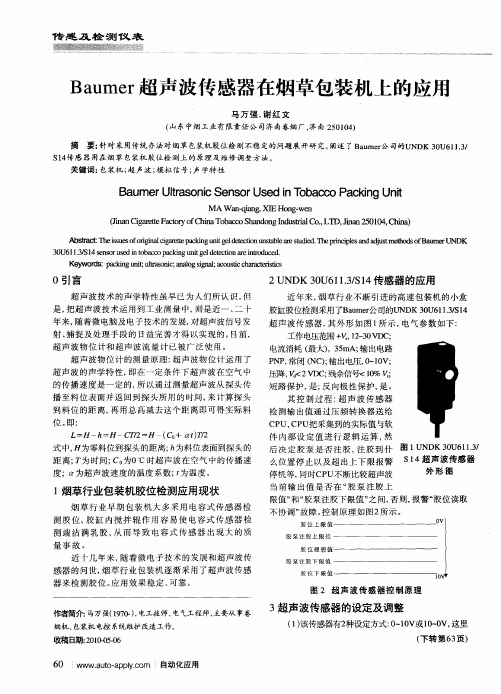
Baumer超声波传感器在烟草包装机上的应用
当前 输 出值 是否在 “ 泵注胶上 胶 限值 ” 胶泵注胶下限值” 和“ 之间, 否则, 报警“ 胶位读取 不协调” 障。 故 控制原理如 图2 所示 。
胶 位 上 限 值
胶 泵 注 胶 上 限 位
测胶 位, 胶缸 内搅 拌辊 作用容 易使 电容式 传感 器检
0引言
超声波技术的声学特性虽早 已为人们所认识 。 但
是, 把超 声 波 技术 运 用 到 工 业 测 量 中, 是 近 一 、 十 则 二
2U DK 0 1. S 4传感器的应用 N 3U6 1 / 1 3
近年来, 烟草行业不断引进 的高速包装机 的小盒
胶缸胶位 检测采用 了B u r 司的U D 0 6 3 1 ame 公 N K3U 1.S 4 1/
S 4 感 器 用在 烟 草 包装 机 胶 位 检 测 上 的 原 理 及 维 修 调 整 方 法 。 1传
关 键词: 包装机 ; 超声波 ; 模拟信 号; 学特 性 声
B u r t s ncSe s r e o a c a k g Unt a me r o i Ula n o di T b c oP c i i Us n n
AS b【 T es eoo g ac a t pci ui edt tn tt la s d &T e rc l ad d sm t d oB u eU D 旧烈:h ius fr i li r t ak g n gle co usber m i h pi ie n a ut e os f am r N K s in g ee n t e i ta e e nps j h
图 2 超声 波传感器控 制原理
- 1、下载文档前请自行甄别文档内容的完整性,平台不提供额外的编辑、内容补充、找答案等附加服务。
- 2、"仅部分预览"的文档,不可在线预览部分如存在完整性等问题,可反馈申请退款(可完整预览的文档不适用该条件!)。
- 3、如文档侵犯您的权益,请联系客服反馈,我们会尽快为您处理(人工客服工作时间:9:00-18:30)。
传感器有一个同步输入端可以抑制传感器之间的相互影响。如果同步输入端不接, 传感器则根据内部产生的时钟频率工作。在传感器的同步输入端上加载一个脉冲宽 度大于 100 μs 的方波脉冲,可以实现同步工作。同步输入端上的同步脉冲启动一个 测量周期,测量周期由同步脉冲的下降沿触发。持续时间大于 1 s 的低电平或者同 步输入端开路,传感器则根据自身内部频率工作。
3
ḋᴀݙᆍᬍᯊᘩϡ䗮ⶹ
Copyright Pepperl+Fuchs, Printed in Germany
超声波传感器
外形尺寸
UC6000-30GM-E6R2-V15
ø73
19 32.5 112
5
36
27.5 22
型号
UC6000-30GM-E6R2-V15
特性
• 通过可编程接口使用 ULTRA 3000 软件进 行传感器参数设定
• 2 个开关量输出可自由调节 • 迟滞模式可选 • 窗口功能可选 • 同步功能 • 声功率和灵敏度可调 • 温度补偿
ມ-LED ୴/ࢤ
LED !!!!ࣜ
E2
E3
A1
A2
ਸ࠲!1
"ཚ"ۉ/߅ඡ
ਸ࠲!2
RS 232-থ੨
ӈ֣
࿒܈/Պ֭ײཀྵ
(ᆯথ੨ۉમ
UC-30GM-R2 থPC)
41
1: TXD 2: RXD 3: փᆩ 4: ں
32
V15-֭ཀྵ (M12x1)
LED-ش੨
ਸ࠲ݛ๕
1. ਸ࠲ఇ๕ ړA1 < A2 ้Ljघऄྺਸ
A 1 (N.O.) ਸ࠲ 1
A 2 (N.O.) ਸ࠲ 2
ਸ࠲ ۅ1
ړA1 > A2 ้LjघऄྺԿ
A 1 (N.C.) ਸ࠲ 1
A2 (N.C.) ਸ࠲ 2 2. ش੨ఇ๕ A1,A2ᅜࢻ࣑
2 个开关量输出 pnp,¨NO/NC 可选 ≤ 0.1 % 满量程值 200 mA, 短路保护 / 过载保护 ≤ 2.5 V ≤ 0.5 Hz 可调整开关距离的 1 % (缺省设置),可调 ≤ 满量程值的 2 % (带温度补偿) ≤ 0.2 %/K (不带温度补偿)
IEC / EN 60947-5-2
2
3
1
45
符合标准 标准 周围环境 环境温度 储存温度 机械特性 防护等级 连接方式 材料
外壳
换能器 重量
1
ḋᴀݙᆍᬍᯊᘩϡ䗮ⶹ
LED
温度补偿 编程插头
M30x1.5
350 ... 6000 mm 400 ... 6000 mm 0 ... 350 mm 100 mm x 100 mm 约 65 kHz 最小 285 ms 出厂设定 850 ms
常亮:通电 闪烁:待机模式或设定状态下检测到目标物 常亮:开关状态开关输出 1 闪烁:设定功能 常亮:开关状态开关输出 2 闪烁:设定功能 常亮:温度 / 设定插头未连接 闪烁:出错或设定状态下未检测到目标物 温度补偿,开关点设定,输出功能设定
10 ... 30 V DC, 纹波 10 %PP ≤ 50 mA
A 1 (N.O.) ਸ࠲ 1
A2 (N.C.) ਸ࠲ 2 3. ውࢫఇ๕ A1,A2ᅜࢻ࣑ A 1 (N.O.) ਸ࠲ 1
A2 (N.C.) ਸ࠲ 2
附件
BF 5-30
安装附件
BF 30
安装附件
6.0 7.0 8.0 9.0 ਐ X [m]
ਸ࠲ ۅ2
注: 如果不需要使用同步功能,同步输入端必须接地 (0 V) 或者使用 V1 连接器 (4 针 )。
用接口电缆 UC-30GM-R2 通讯的说明
通过 UC-30GM-R2 接口电缆使用 ULTRA 3000 应用软件可实现与超声波传感器的通讯。电缆连接了 PC 232 串口和传感器的温 度 / 设定插头。当建立与传感器的连接时,请确认插头排列正确,否则通讯不能建立。圆形插头的突出部分必须被插入到传感 器侧插座的凹槽处而不是箭头标志处。
RS 232, 9600 Bit/s, 无奇偶校验 , 8 数据位 , 1 停止位
双向 0-level: -UB ... +1 V 1-level: +4 V ... +UB 输入阻抗 : > 12 kΩ 同步脉冲 : ≥ 100 μs, 同步脉冲周期 : ≥ 2 ms
≤ 7 Hz ≤ 7/n Hz, n = 传感器数量
ḋᴀݙᆍᬍᯊᘩϡ䗮ⶹ
Copyright Pepperl+Fuchs, Printed in Germany
2
超声波传感器
LED 显示 运行状态
开关点 A1 设置 检测到目标 未检测到目标 开关点 A2 设置 检测到目标 未检测到目标 输出模式设置 (E2/E3) 开关点模式 窗口模式 迟滞模式 正常工作模式 温度补偿 设定插头拔出或短接 干扰 (如:压缩空气) 待机模式 LED 灯亮指示开关输出闭合
用应用软件 ULTRA 3000 设定参数 - 开关点 1 和 2 - NO/NC 功能 - 工作模式 - 声速 - 温度漂移 (对固有的传感器温升可考虑在温度补偿内) - 盲区扩展 (用于抑制盲区回声) - 检测范围的缩小 (用于远程回声的抑制) - 测量周期的时间 - 声功率 (脉冲串周期的干扰) - 灵敏度 - 回波丢失时传感器的动作 - 出错时传感器的动作 - 允许测量周期数的平均值 - 响应 / 关断延时 - 开关迟滞 - 参数设定选择, RS232 或人工设定
+ UB ཞօ ਸ࠲ଉ!1 ਸ࠲ଉ!2
- UB
温度 / 设定插头 电气参数 工作电压 空载电流 I0 接口 接口类型 输入 / 输出 同步
同步频率 一般操作模式 多重操作模式 输出 输出类型 重复精度 额定工作电流 Ie 电压降 Ud 开关频率 f 迟滞范围 H 温度漂移
V15 থഗ
UC6000-30GM-E6R2-V15
双 LED 红 色 黄色 LED A1
绿
LED
黄色 LED A2
闪
暗
闪
暗
暗
闪
闪
暗
闪
暗
暗
闪
暗
闪
暗
闪
亮
暗
闪
暗
亮
暗
暗
闪
亮
暗
闪
闪
亮
暗
开关状态 A1
开关状态 A2
暗
亮
开关状态 A1
开关状态 A2
暗
闪
上次或规定状态 上次或规定状态
闪
暗
先前状态
先前状态
LED-ش੨
LED !!!!ࣜ
出厂设置
A1: A2:
盲区 最大量程
UC-30GM-TEMP
附件
UC-30GM-PROG
附件
ULTRA3000
软件
UC-30GM-R2
附件
V15-G-2M-PVC
电缆连接器
V15-W-2M-PVC
电缆连接器
Release date: releasedate Issue date: 2007-10-09 102163_CN.xml
功能 设定开关点 A1 设定开关点 A2 设定工作模式:开关点模式 / 窗口模式 / 迟滞模式 温度补偿
设定过程说明
设定开关点 1 或 2 - 切断电源 - 拔下设定插头 - 再次通电 (重启) - 把目标物放置在所需的开关点上 - 把插头插入对应的 A1 或 A2 位置再拔出,开关点 A1 和 A2 就设定完成了。
Release date: releasedate Issue date: 2007-10-09 102163_CN.xml
超声波传感器
UC6000-30GM-E6R2-V15
传感器功能说明 传感器有一个四针的温度 / 设定插头,可以从四个不同的位置插入,具体功能如下:
插头位置 A1 A2 E2/E3 T
-25 ... 70 ºC (248 ... 343 K) -40 ... 85 ºC (233 ... 358 K)
IP65 V15 连接器 ( M12 x 1), 5 针
不锈钢 1.4303 塑料部分 PBT 环氧树脂 / 空心玻璃球混合物 ; 聚氨基甲酸酯泡沫体 270 克
Copyright Pepperl+Fuchs, Printed in Germany
因为同步功能增加了测量周期时间,所以当传感器同步工作时,响应时间将增加。
特性曲线 / 其它信息
ၚᆌ༬Ⴀ൸၍
ਐ Y [m] 1.5
1.0
1
0.5
2
0.0
-0.5
-1.0
-1.5 0.0 1.0 2.0 3.0 4.0 5.0
Y X
൸၍1ǖೝӱ 100 mm x 100 mm ൸၍2ǖᇶԀ Ø 25 mm
• 开关点模式, LED A1 灯闪烁 • 窗口模式, LED A2 灯闪烁 • 迟滞模式, LED A1 和 A2 灯同时闪烁 - 将设定插头插入 T 位置,设定过程结束,传感器进入正常工作模式。
说明:如果温度 / 设定插头在五分钟内未插入 T 位置,传感器将进入正常工作模式 (带最新储存的参数值),但将失去温度补偿功能。
注意: 拔出温度 / 设定插头的同时,目标物位置值将被保存 - 设定过程可由 LED 灯指示。绿灯闪烁时,目标物被检测到;红灯闪烁时,目标物
未被检测到。 - 将设定插头插入 T 位置,设定过程结束,传感器进入正常工作模式。
设定输出功能 - 切断电源 - 拔出设定插头 - 再次通电 (重启) - 将设定插头插入 E2/E3 位置,通过多次拔插,可循环地设置三种不同的输出模式: