TURCK 超声波传感器选型手册(中文)2005.10.10
TURCK FS100-300L-62-2UPN8-H1141 流量传感器产品说明书
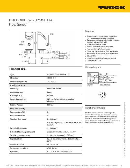
F S 100-300L -62-2U P N 8-H 1141 | 02/03/2020 14-09 | t e c h n i c a l c h a n g e s r e s e r v e dFS100-300L-62-2UPN8-H1141Flow SensorTechnical dataFS100-300L-62-2UPN8-H1141100001014Medium temperature-25…+85 °C Application areaImmersion sensor Application area liquids Bar length (L1)93 mmImmersion depth (L)64.9 mm(when using the supplied adapter) Process Pressure300 bar Flow MonitoringResponse time T096 s Response time T053 sStandard flow range3…300 cm/sAny axial alignment of the sensor rod in the mediumExtended flow range1…300 cm/sExtended flow range comment Directed inflow to punch mark ±20 °Switching point accuracy 1…30 cm/s; for water 3…300 cm/s Reproducibility 0.2…5 cm/s; for water 3…100 cm/s; 10…80 °C Temperature drift 0.5 cm/s × 1/K Temperature gradient ≤ 300 K/min3 … 25 % of the switching pointFeatures■Screw-in adaptor with process connection G1/2" male thread included in delivery■Electronics housing material/medium contact 1.4404 (316L)/1.4571 (316Ti)■Immersion depth 64.9 mm■Process value display with bar graph ■Flow monitoring for liquid media■Protection classes IP6K6K, IP6K7 and IP6K9K ■Adjustment of flow speed via teach function ■10…33 VDC■NO/NC contact, PNP/NPN output, IO-Link ■Connector, M12 × 1Wiring diagramFunctional principleThe flow sensor functions according to the calorimetric principle. The distinctive feature of this principle is that the flow rate correlates directly to the thermal loss of energy in theprobe. The increased loss of energy is therefore a direct measure of an increased flow rate.F S 100-300L -62-2U P N 8-H 1141 | 02/03/2020 14-09 | t e c h n i c a l c h a n g e s r e s e r v e d Technical dataF S 100-300L -62-2U P N 8-H 1141 | 02/03/2020 14-09 | t e c h n i c a l c h a n g e s r e s e r v e dTechnical dataMounting instructionsF S 100-300L -62-2U P N 8-H 1141 | 02/03/2020 14-09 | t e c h n i c a l c h a n g e s r e s e r v e dfrom being modified accidentally, for example.Teach functions (Quick and MAX/MIN)Quick Teach allows quick teaching in of theswitchpoint without teaching in a separate MAX/MIN range. With MAX/MIN Teach on the other hand, the flow range to be monitored is scaled to two limit values to be taught and the switchpoint is set within these two limits. Sensors with a switching output have both modes, whereas sensors without a switching output only have MAX/MIN Teach.F S 100-300L -62-2U P N 8-H 1141 | 02/03/2020 14-09 | t e c h n i c a l c h a n g e s r e s e r v e d LED displayLED Color Status DescriptionPWR Green On Operating voltage applied Device is operationalFlashingOperating voltage applied IO-Link communication active(inverted flash with T on 900 ms and T off 100 ms)FLT Red On Error displayed(for error pattern in combination with LEDs see manual)Off No errors displayed LOC Yellow On Device locked OffDevice unlockedFlashing Locking/unlocking process activeFLOWYellowOn NO: Flow switchpoint exceeded (output "high")NC: Flow below minimum switchpoint (output "high")Off NO: Flow below minimum switchpoint (output "low")NC: Flow switchpoint exceeded (output "low")FlashingTeach mode/display of diagnostic data (see manual for specification)TEMP YellowOnNO: Temperature switchpoint exceeded (output "high")NC: Temperature below minimum switchpoint (output "high")Off NO: Temperature below minimum switchpoint (output "low")NC: Temperature switchpoint exceeded (output "low")FlashingTeach mode/display of diagnostic data (see manual for specification)For detailed description of the display patterns and flashing codes, see manual D100002084IO-Link process data imageBit 1514131211109876543210Byte n 14 Bit Process Value (TEMP)State Out 2 (TEMP)State Out 1 (FLOW)Bit31302928272625242322212019181716Byte n+116 Bit Process Value (FLOW)Accessories Wiring accessoriesDimension drawingTypeIdent. no.RKC4.4T-2/TEL6625013Connection cable, female M12, straight,4-pin, cable length: 2 m, sheath material:PVC, black; cULus approval; other cable lengths and qualities available, see WKC4.4T-2/TEL 6625025Connection cable, female M12, angled,4-pin, cable length: 2 m, sheath material:PVC, black; cULus approval; other cable lengths and qualities available, see Accessories。
Turck双检测面电感式传感器说明书

T 04:44:13+02:00型号NI4-DSU35TC-2Y1X2/S1176货号1051018额定工作距离Sn 4 mm 安装方式非齐平修正系数37#钢 = 1; 铝 = 0.3; 不锈钢= 0.7; 黄铜 = 0.4重复精度ð 2 满量程的 %温度漂移10 %磁滞1…10 %环境温度-25…+70 °C 输出性能4线, NAMUR 阀控制Exi (max. 30 V)开关频率0.05 kHz电压Nom. 8.2 VDC 无激励电流损耗ï 2.1 mA 激励电流损耗ð 1.2 mA认证依据KEMA 02 ATEX 1090X 内置 电感(L ) / 电容 (C )150 nF / 150 µH防爆标志防爆标识为II 2 G/Ex ia IIC T6 Gb /II 1 D Ex ia D 20T95 °C Da(最大 U = 20 V, I = 60 mA, P = 200 mW)警告防静电设计用于阀位回讯检测的双检测面电感式传感器, DSU35尺寸62 x 60 x 35 mm外壳材料塑料, 塑料, PA12-GF20, 黄感应面材料塑料, 塑料, PA12-GF20, 黑连接接线端子夹紧能力ð 2.5 mm 防震动性55 Hz (1 mm)防冲击性30 g (11 ms)防护等级IP67开关状态指示2路LED指示灯 黄/黄可供货2个导线密封套(蓝),2个导线密封套的密封圈,1个M20x1密封塞,1个商标sATEX 防爆认证II 组设备,设备等级2G. 可用于气体危险1区sATEX 防爆认证,II组设备,可应用于粉尘危险0区s 满足SIL2和IEC61508标准s 长方形,外壳类型DSU35s 塑料, PP -GF30-V0s 检测旋转执行器位置两路输出s 在标准执行器上安装s 不锈钢材质的快插和螺纹拧接的插头s 2线直流, nom. 8.2 VDCs输出遵循本安型DIN EN 60947-5-6标准(NAMUR)s接线端子接线图功能原理电感式传感器以无磨损和非接触的方式来检测金属物体 阀位回讯是专为旋转执行器的位置检测而设计的 它将非接触式电感传感器的可靠性与模块化的外壳系统的灵活性结合起来。
长距离超声波传感器数据手册说明书

DatasheetLong-range ultrasonic sensors with TEACH-mode programming•Fast, easy-to-use TEACH-Mode programming; no potentiometer adjustments •Scalable output automatically distributes the output signal over the width of the programmed sensing window•Minimum and Maximum window limits can be adjusted independently •Selectable 0 to 10 V dc or 4 to 20 mA output, selected via DIP switch•Access to bank of 8 DIP switches through sealed cover for superior user functionality •Rugged encapsulated design for harsh environments•Unique housing design allows for multiple mounting configurations•Choose models with integral unterminated 2 m (6.5 ft) or 9 m (30 ft) cable, or with Mini-style or M12/Euro-style quick-disconnect connection•Wide operating range of −20 °C to +70 °C (−4 °F to +158 °F)•Temperature compensation•Programmable for either positive or negative output slopeWARNING: Not To Be Used for Personnel ProtectionNever use this device as a sensing device for personnel protection. Doing so could lead to serious injury or death.This device does not include the self-checking redundant circuitry necessary to allow its use in personnel safety applications. A sensor failure or malfunction can cause either an energized or de-energized sensor output condition.Principles of OperationUltrasonic sensors emit one or multiple pulses of ultrasonic energy, which travel through the air at the speed of sound. A portion of this energy reflects off the target and travels back to the sensor. The sensor measures the total time required for the energy to reach the target and return to the sensor. The distance to the object is then calculated using the following formula: D = ct ÷ 2D = distance from the sensor to the target c = speed of sound in airt = transit time for the ultrasonic pulseTo improve accuracy, an ultrasonic sensor may average the results of several pulses before outputting a new value.TemperatureEffectsThe speed of sound is dependent upon the composition, pressure and temperature of the gas in which it is traveling. For most ultrasonic applications, the composition and pressure of the gas are relatively fixed, while the temperature may fluctuate.In air, the speed of sound varies with temperature according to the following approximation:In metric units:C m/s = 20 √273 + T C In English units:ft/s = 49 √460 + T F CC m/s = speed of sound in meters per second C ft/s = speed of sound in feet per second T C = temperature in °CT F = temperature in °F .suffix “w/30” to the model number of a cabled sensor (e.g., QT50ULB w/30). Models with a QD connector require a mating cable.U-GAGE ® QT50ULB Series Sensors with Analog OutputOriginal Document 70137 Rev. C27 July 201770137In metric units:C m/s = 20 √273 + T CIn English units:ft/s = 49 √460 + T F CC m/s = speed of sound in meters per second C ft/s = speed of sound in feet per second T C = temperature in °CT F = temperature in °FThe speed of sound changes roughly 1% per 6° C (10° F). QT50U series ultrasonic sensors have temperature compensation available, viathe 8-pin DIP switch. Temperature compensationwill reduce the error due to temperature by about 90%.Note: If the sensor is measuring across a temperature gradient, the compensation will be less effective.Analog Output SlopeThe U-GAGE QT50ULB Sensor may be programmed for either a positive or a negative output slope, depending on which conditions are taught for the Min and Max Analog limits. If the Min Analog limit is the Near Window setting and the Max Analog limit is the Far Window setting, then the slope will be positive. If the opposite is true, then the slope will be negative.Current-Sourcing ModelsTarget PositionPositive SlopeNear WindowFar WindowA n a l o g O u t p u t (m A )204Negative SlopeVoltage-Sourcing ModelsTarget PositionPositive SlopeNear WindowFar WindowV o l t a g e O u t p u t (V d c )100Negative SlopeFigure 1. Positive and Negative Output SlopsConfiguration - Tel: +1-763-544-3164P/N 70137 Rev. C* Factory default settingDIP Switch Selectable FunctionsCAUTION: To avoid damage to the sensor caused by static discharge (ESD), observe proper ESD precautions(grounding) while adjusting the DIP switches.Switch 1: Output Mode SelectON = 4 to 20 mA current output is enabledOFF = 0 to 10 V dc voltage output is enabledSwitch 1 configures the sensor internally to use either the current output or voltage output configuration.Switch 2: Loss of Echo Mode SelectON = Min-Max ModeOFF = Hold ModeSwitch 2 determines the output response to the loss of echo. “Min-Max Mode” (Switch 2 ON) drives the output to either the minimum value or the maximum value when the echo is lost. (Minimum or Maximum value is selected via Switch 3.)“Hold Mode” (Switch 2 OFF) maintains the output at the value which was present at the time of echo loss.Switch 3: Min-Max DefaultON = Default to maximum output value at loss of echo (10.5 V dc or 20.8 mA)OFF = Default to minimum output value at loss of echo (0 V dc or 3.6 mA)Switch 3 selects the output response to loss of echo when “Min-Max Mode” is selected via Switch 2. When Switch 2 is OFF, Switch 3 has no function.Switch 4: Teach/Transmit Enable ControlON = Gray (or yellow) wire configured for remote teachOFF = Gray (or yellow) wire configured for transmit enable/disable: High (5 to 30 V dc) - Transmit Enabled (Power LED solid Green);Low (0 to 2 V dc) - Transmit Disabled (Power LED flashes at 2 Hz)When Switch 4 is ON, the gray wire is used to teach window limits to the sensors.When Switch 4 is OFF, the gray wire is used to enable and disable the sensor’s transmit burst. The sensor output will react as if a “loss of echo” occurred and either hold the output or change to minimum or maximum value (depending on switch 2 and 3 settings). This function may be used when multiple sensors are in close proximity, which may make them vulnerable to crosstalk interference. A PLC can be used to enable the sensors one at a time to avoid crosstalk.Switches 5 and 6: Response Speed AdjustmentSwitches 5 and 6 are used to set the speed of the output response. The four values for response speed relate to the number of sensing cycles over which the output value is averaged.Switch 7: Temperature CompensationON = Temperature compensation enabledOFF = Temperature compensation disabledChanges in air temperature affect the speed of sound, which in turn affects the distance reading measured by the sensor. An increase in air temperature shifts both sensing window limits closer to the sensor. Conversely, a decrease in air temperature shifts both limits farther away from the sensor. This shift is approximately 3.5% of the limit distance for a 20 °C change in temperature. With temperature compensation enabled (Switch 7 ON), the sensor will maintain the window limits to within 1.8 percent over the –20 °C to 70 °C range. The temperature sensor in the sensor’s bezel cannot adapt to temperature change as quickly as an external temperature device can. When there are fast fluctuations in temperature, it may be best to use an external temperature monitor and feed its signal and the uncompensated distance measurement into a controller and perform the compensation calculations within the controller.P/N 70137 Rev. C - Tel: +1-763-544-31643Consult the factory for details on performing temperature compensation calculations.•If temperature compensation is enabled, exposure to direct sunlight can affect the sensor’s ability to accurately compensate for changes in temperature.•With temperature compensation enabled, the temperature warmup drift upon power-up is less than 0.8% of the sensing distance. After 15 minutes, the apparent distance will be within 0.5% of the actual distance. After 30 minutes, the apparent distance will be within 0.3% of the actual distance.Switch 8: Factory CalibrationON = Factory calibration onlyOFF = Normal operationFigure 4. Sensor Features MIN - Minimum limit indicatorMAX - Maximum limit indicator POWER - Sensor power indicator SIGNAL - Target signal strength indicatorGeneral Notes on Programming•The sensor returns to RUN mode if the limit is not registered within 120 seconds after entering TEACH Mode.•Press and hold the programming push button for more than 2 seconds (before teaching the limit) to exit PROGRAM mode without saving any changes. The sensor will revert to the last saved program.•If the push buttons do not respond, perform a remote lockout procedure to enable push buttons.Sensor ProgrammingTwo TEACH methods may be used to program the sensor:•Teach individual minimum and maximum limits•Use the Auto-Window feature to center a sensing window around the taught positionThe sensor may be programmed either via its two push buttons, or via a remote switch. Remote programming also may be used to disable the push buttons,preventing unauthorized personnel from adjusting the programming settings. To access this feature, connect the gray wire of the sensor to 0–2 V dc, with a remote programming switch between the sensor and the voltage.Note: The impedance of the Remote Teach input is 12 kΩ.Programming is accomplished by following the sequence of input pulses. The duration of each pulse (corresponding to a push button “click”), and the period between multiple pulses, are defined as “T” where 0.04 seconds < T < 0.8 seconds.Teaching Minimum and Maximum LimitsThe Min and Max Analog limits are independent. To readjust either limit, it is necessary to follow the teach procedure for that limit only. Setting the Minimum Analog Limit - Tel: +1-763-544-3164P/N 70137 Rev. CSetting the Maximum Analog LimitTeaching Limits Using the Auto-Window FeatureTeaches a sensing distance threshold centered within a fixed sensing window (a 1 m window centered on the position taught). This procedure centers the analog output on the taught position at approximately 5 V dc or 12 mA.Setting the Minimum Analog LimitSetting the Maximum Analog LimitP/N 70137 Rev. C - Tel: +1-763-544-31645Push Button LockoutThe Push Button Lockout feature enables or disables the keypad to prevent unauthorized personnel from adjusting the programming settings. This feature is not available using the buttons.Status IndicatorsMin Max MaxMinimum Operating RangeMinimum Analog SetpointMaximum Analog SetpointMaximum OperatingRangeTarget Within LimitsTarget Outside Min Limit Target Outside Sensing RangeTarget Outside Max LimitFigure 5. Status Indicator Conditions for Each Target Position - Tel: +1-763-544-3164P/N 70137 Rev. CWiringBanner recommends connecting the shield wire to earth ground or dc common.P/N 70137 Rev. C - Tel: +1-763-544-31647DimensionsSpecificationsSupply Voltage and Current10 to 30 V dc (10% maximum ripple)100 mA max at 10 V, 40 mA max at 30 V (exclusive of load)Sensing Range200 mm to 8 m (8 inches to 26 feet)Ultrasonic Frequency75 kHz burst, rep. rate 96 msSupply Protection CircuitryProtected against reverse polarity and transient overvoltages Output ProtectionProtected against short circuit conditions Delay at Power-up1.5 secondsAnalog Output Configuration (Voltage Sourcing: 0 to 10 V dc)Minimum Load Resistance = 500 ohmsMinimum Required Supply Voltage for Full 0-10 V Output Span = (1000/RLoad + 13) V dc Analog Output Configuration (Current Sourcing: 4 to 20 mA)Maximum Load Resistance = 1 k Ω or ( Vsupply/0.02 - 5) ohms, whichever is lowerMinimum required supply voltage for full 4-20 mA output span = 10 V dc or [(RLoad × 0.02) + 5] V dc, whichever is greater.4 to 20 mA output calibrated at 25 °C with a 250 Ω load.Temperature EffectUncompensated: 0.2% of distance/°C Compensated: 0.02% of distance/°CLinearity+/- 0.2% of span from 200 to 8000 mm+/- 0.1% of span from 500 to 8000 mm (1 mm minimum)Resolution1.0 mmOutput Response Time100 ms to 2300 msSee DIP Switches 5 and 6Minimum Window Size20 mmAdjustmentsSensing window limits: TEACH-Mode programming of near and far window limits may be set using the push buttons or remotely via TEACH input.IndicatorsGreen Power On LED: Indicates power is ONRed Signal LED: Indicates target is within sensing range, and the condition of the received signalTeach/Output indicator (bicolor Amber/Red): Amber – Target is within taught limits; Flashing Amber – Target is outside taught window limits; Red – Sensor is in TEACH mode Remote TEACHTo Teach: Connect gray or yellow wire to 0 to 2 V dc; impedance 12 k ΩConstructionTransducer: Ceramic/Epoxy composite Housing: ABS/Polycarbonate Membrane Switch: Polyester Lightpipes: Acrylic Operating ConditionsTemperature: –20 °C to 70 °C (–4 °F to 158 °F)Maximum relative humidity: 100%Connections2 m (6.5 ft) or 9 m (30 ft) shielded 5-conductor (with drain) PVC jacketed attached cable or 5-pin Euro-style quick-disconnect or 5-pin Mini-style quick-disconnect Environmental RatingLeakproof design is rated IEC IP67; NEMA 6PVibration and Mechanical ShockAll models meet Mil Std. 202F requirements. Method 201A (vibration: 10 to 60Hz max., double amplitude 0.06", maximum acceleration 10G). Also meets IEC 947-5-2 requirements: 30G 11 ms duration, half sine wave Temperature Warmup DriftLess than 0.8% of sensing distance upon power-up with Temperature Compensation enabled (see Temperature Compensation)Application NotesObjects passing inside the specified near limit (200 mm) may produce a false response.Certifications - Tel: +1-763-544-3164P/N 70137 Rev. CPerformance CurvesE f f e c t i v e B e a m W i d t hTarget Distance1 m (3.3')2 m (6.6')3 m (9.8')4 m (13.1')5 m (16.4')6 m (19.6')7 m (22.9')8 m (26.2')8"-8"016"-16"24"-24"31"-31"-40"40"-10-20-30100203040-400Target Distance (m)T a r g e t R o t a t i o n (d e g )1 m (3.3’)2 m (6.6’)3 m (9.8’)4 m (13.1’)5 m (16.4’)6 m (19.6’)7 m (22.9’)8 m (26.2’)AccessoriesCordsetsP/N 70137 Rev. C - Tel: +1-763-544-31649BracketsBanner Engineering Corp Limited WarrantyBanner Engineering Corp. warrants its products to be free from defects in material and workmanship for one year following the date of shipment. Banner Engineering Corp. will repair or replace, free of charge, any product of its manufacture which, at the time it is returned to the factory, is found to have been defective during the warranty period. This warranty does not cover damage or liability for misuse, abuse, or the improper application or installation of the Banner product.THIS LIMITED WARRANTY IS EXCLUSIVE AND IN LIEU OF ALL OTHER WARRANTIES WHETHER EXPRESS OR IMPLIED (INCLUDING, WITHOUT LIMITATION, ANY WARRANTY OF MERCHANTABILITY OR FITNESS FOR A PARTICULAR PURPOSE), AND WHETHER ARISING UNDER COURSE OF PERFORMANCE, COURSE OF DEALING OR TRADE USAGE. - Tel: +1-763-544-3164P/N 70137 Rev. CU-GAGE® QT50ULB Series Sensors with Analog Output This Warranty is exclusive and limited to repair or, at the discretion of Banner Engineering Corp., replacement. IN NO EVENT SHALL BANNER ENGINEERING CORP. BE LIABLE TO BUYER OR ANY OTHER PERSON OR ENTITY FOR ANY EXTRA COSTS, EXPENSES, LOSSES, LOSS OF PROFITS, OR ANY INCIDENTAL, CONSEQUENTIAL OR SPECIAL DAMAGES RESULTING FROM ANY PRODUCT DEFECT OR FROM THE USE OR INABILITY TO USE THE PRODUCT, WHETHER ARISING IN CONTRACT OR WARRANTY, STATUTE, TORT, STRICT LIABILITY, NEGLIGENCE, OR OTHERWISE.Banner Engineering Corp. reserves the right to change, modify or improve the design of the product without assuming any obligations or liabilities relating to any product previously manufactured by Banner Engineering Corp. Any misuse, abuse, or improper application or installation of this product or use of the product for personal protection applications when the product is identified as not intended for such purposes will void the product warranty. Any modifications to this product without prior express approval by Banner Engineering Corp will void the product warranties. All specifications published in this document are subject to change; Banner reserves the right to modify product specifications or update documentation at any time.Specifications and product information in English supersede that which is provided in any other language. For the most recent version of any documentation, refer to: .© Banner Engineering Corp. All rights reserved。
TURCK NI3-EH6.5K-Y1 非陶瓷感应传感器技术数据手册说明书

TURCK Inc. | 3000 Campus Drive Minneapolis, MN 55441-2656 | Phone: 763-553-7300 | Application Support: 1-800-544-7769 | Fax 763-553-0708 | 1|3N I 3-E H 6.5K -Y 1 | 11/29/2022 05-08 | t e c h n i c a l c h a n g e s r e s e r v e dNI3-EH6.5K-Y1Inductive SensorTechnical dataNI3-EH6.5K-Y11004700 Rated switching distance 3 mmNon-flush Secured operating distance ≤ (0.81 × Sn) mmSt37 = 1; Al = 0.3; stainless steel = 0.7; Ms = 0.4≤ 2 % of full scale ≤ ±10 %1…10 %2-wire, NAMUR 5 kHz Nom. 8.2 VDC Non-actuated current consumption ≥ 2.1 mA Actuated current consumption ≤ 1.2 mAKEMA 02 ATEX 1090X )/inductance (L i )150 nF/150 µHÉ II 1 G Ex ia IIC T6 Ga/II 1 D Ex ia IIIC T135 °C Da(max. U i = 20 V, I i = 60 mA, PSmooth barrel, 6.5 mm 23.6 mmFeatures■Smooth barrel, Ø 6.5 mm ■Stainless steel, 1.4427 SO ■DC 2-wire, nom. 8.2 VDC■Output acc. to DIN EN 60947-5-6 (NAMUR)■Cable connection■ATEX category II 1 G, Ex zone 0■ATEX category II 1 D, Ex zone 20■SIL2 (Low Demand Mode) acc. to IEC 61508,PL c acc. to ISO 13849-1 at HFT0■SIL3 (All Demand Mode) acc. to IEC 61508,PL e acc. to ISO 13849-1 with redundant configuration HFT1Wiring diagramFunctional principleInductive sensors detect metal objectscontactless and wear-free. For this, they use a high-frequency electromagnetic AC field that interacts with the target. Inductive sensors generate this field via an RLC circuit with a ferrite coil.Technical dataMounting instructionsMounting instructions/Description22/92/11|1Y-K5.6HE-3IN TURCK Inc. | 3000 Campus Drive Minneapolis, MN 55441-2656 | Phone: 763-553-7300 | Application Support: 1-800-544-7769 | Fax 763-553-0708 | 2|3TURCK Inc. | 3000 Campus Drive Minneapolis, MN 55441-2656 | Phone: 763-553-7300 | Application Support: 1-800-544-7769 | Fax 763-553-0708 | 3|3N I 3-E H 6.5K -Y 1 | 11/29/2022 05-08 | t e c h n i c a l c h a n g e s r e s e r v e dInstructions for useIntended useThis device fulfills Directive 2014/34/EC and is suited for use in areas exposed to explosion hazards according to EN 60079-0:2018 and EN 60079-11:2012.Further it is suited for use in safety-related systems, including SIL2 as per IEC61508.In order to ensure correct operation to the intended purpose it is required to observe the national regulations and directives.For use in explosion hazardous areas conform to classificationII 1 G and II 1 D (Group II, Category 1 G, electrical equipment for gaseous atmospheres and category 1 D, electrical equipment for dust atmospheres).Marking (see device or technical data sheet)É II 1 G and Ex ia IIC T6 Ga and É II 1 D Ex ia IIIC T135 °C Da acc. to EN 60079-0, -11Local admissible ambient temperature -25…+70 °CInstallation/CommissioningThese devices may only be installed, connected and operated by trained and qualified staff. Qualified staff must have knowledge of protection classes, directives and regulations concerning electrical equipment designed for use in explosion hazardous areas.Please verify that the classification and the marking on the device comply with the actual application conditions.This device is only suited for connection to approved Exi circuits according to EN 60079-0 and EN 60079-11. Please observe the maximum admissible electrical values.After connection to other circuits the sensor may no longer beused in Exi installations. When interconnected to (associated) electrical equipment, it is required to perform the "Proof of intrinsic safety" (EN60079-14).Attention! When used in safety systems, all content of the security manual must be observed.Installation and mounting instructionsAvoid static charging of cables and plastic devices. Please only clean the device with a damp cloth. Do not install the device in a dust flow and avoid build-up of dust deposits on the device.If the devices and the cable could be subject to mechanical damage, they must be protected accordingly. They must also be shielded against strong electro-magnetic fields.The pin configuration and the electrical specifications can be taken from the device marking or the technical data sheet.Service/MaintenanceRepairs are not possible. The approval expires if the device is repaired or modified by a person other than the manufacturer. The most important data from the approval are listed.。
超声波传感器产品说明说明书

ApplicationThe sensor measures the spectral absorption of process liquids in the ultraviolet region of the electromagnetic spectrum.•Measurement of protein concentrations •Chromatography monitoring •Filtration monitoring •Concentration measurement of organic compounds •Detection of aromatesYour benefits•Improved process control and easier quality control thanks to quick and reliable monitoring of product concentration –Measuring range up to 2.5 AU or 50 OD (depending on optical path length)–Measurement of UV absorption at discrete wavelengths between 254 nm and 313 nm –Outstanding filter properties for highest linearity –Direct concurrence with laboratory values –Integrated reference detector for lamp compensation –Gas discharge lamp for long service life and stable measured values •FM- and ATEX-approved lamps for applications in the hazardous area •Compliance with life sciences sector thanks to hygienic design and FDA- and USP-compliant sealing materials •High degree of product safety as SIP/CIP-resistant •High product yield thanks to low volume requirements •Maximum durability in all applications owing to wide range of materials and process connections •Can be adapted to process requirements:Optional air purge ports to prevent the formation of condensate on the optical windowsProducts Solutions ServicesTechnical Information OUSAF46Optical sensor with the OUA260 flow assembly for the measurement of UV absorptionTI01190C/07/EN/02.1771388454OUSAF462Endress+HauserFunction and system designMeasuring principle Light absorption The measuring principle is based on the Lambert-Beer law.There is a linear dependency between the absorption of light and the concentration of the absorbing substance:A = -log(T) = ε . c . OPL T = I/I 0T ... Transmission I ... Intensity of received light at detector I 0 ... Intensity of transmitted light of light source A ... Absorption ε ... Extinction coefficient c ... Concentration OPL ... Optical path lengthA light source emits radiation through the medium and the incident radiation is measured on the detector side.The subsequent conversion to absorbance units (AU, OD) is performed in the associated transmitter.1Absorption measurement with reference 1Light source 2Optical windows 3Measurement filter 4Measuring detector 5Lens 6Medium flow 7Reference filter 8Reference detectorOUSAF46 has 2 pairs of reference and measuring detectors (= 2 channels). Only one channel is shown for the sake of simplicity.Measuring system An optical measuring system comprises:•Sensor (photometer) OUSAF46•Transmitter, for example Liquiline CM44P •Cable set, for example CUK80•Assembly OUA260OUSAF46Endress+Hauser 32Example of a measuring system with a photometer sensor 1pipe 5Flow assembly OUA2602Transmitter CM44P 6Sensor: light source (lamp)3CUK80 cable set 7CUK80 cable set 4Sensor: detector InputMeasured variableUV-absorption Measuring range •0 to 2.5 AU •Max. 50 OD (depending on the optical path length)WavelengthDiscrete wavelength at 254, 280, 295 or 313 nm Power supplyElectrical connection The sensor is connected to the transmitter using the pre-terminated or labeled cable set CUK80 (for connection to CM44P) or OUK (for connection to CVM40) . The terminals and labeling may vary depending on the transmitter in use. The cable set must be ordered separately.OUSAF464Endress+Hauser3OUSAF46 connecting cable ALight source (lamp) power supply B Signals of measurement and reference detectorCable lengthMaximum 100 m (330 ft)Lamp voltage Versions for use inhazardous areas 1)Safety instructions for electrical apparatus in explosion-hazardous areas, XA01403CConnecting the detector using a safety barrierThe photometer sensors use silicon photovoltaic cells as detectors which are operated in the current mode. The detectors are intrinsically safe and can be deployed in Zone 1 and Class I, Division 1environments.1)Applies only to measuring points consisting of a photometer, CUK80 cable set and Liquiline CM44P transmitter.OUSAF46Endress+Hauser 5The safe area is separated from the hazardous area by safety barrier MTL7760AC.4Safety barrier, dimensions in mm (inch)The safety barrier may only have a very low leak current since the optical signals from the sensor can be in the nanoampere range. Therefore, the sensor cable shield is connected to the ground terminal of the barrier.On delivery, the CUK80 detector cable is permanently wired to the . All you have to do is simply connect the individual cable ends to the detector and transmitter.Connecting the hazardous area lamp using a junction boxThe hazardous area lamp (EXP-1) must be connected to the transmitter using a certified junction box.For versions with FM approval, the junction box is included in the delivery and already pre-terminated on the lamp side. You simply have to connect the cable of the transmitter (CUK80)to the terminals of the junction box.For versions with ATEX approval, the junction box is not included in the delivery and it and the cable glands required must be provided by the customer at the place of installation. You must connect the cables entirely on your own (CUK80 of transmitter and lamp cable of photometer sensor).OUSAF466Endress+HauserInstallation5Mounting angles. The arrows indicate the direction of medium flow in the pipe.ASuitable mounting angle, better than C BOptimum mounting angle, best installation position CAcceptable mounting angle DMounting angle to be avoided E Forbidden mounting angleEnvironmentAmbient temperature0 to 55 °C (32 to 130 °F)Storage temperature-10 to +70 °C (+10 to +160 °F)Humidity5 to 95 %Degree of protection IP 65 (NEMA 4) for all optical partsProcessProcess temperature 0 to 90 °C (32 to 194 °F) continuousMax. 130 °C (266 °F) for 2 hoursProcess pressure Max. 100 bar (1450 psi) absolute, depending on the material, pipe size and process connection of the flow assemblyOUSAF46Endress+Hauser 7Mechanical construction6Sensor module ADimension of lamp → Table BDimension of detector → Table C Assembly, see Technical Information for assembly The total length of the sensor module is derived from the lengths of the lamp, the detector and the assembly.The dimensions of the OUA260 assembly are provided in Technical Information, TI00418C.‣Allow an additional gap of 5 cm (2") on both the lamp side and detector side of the sensor to connect the sensor cable.Weight SensorUV lamp0.58 kg (1.28 lbs)UV lamp with wire-braided cable (1.2 m (4 ft)) and junction box (sensor for hazardous area)3.2 kg (6.66 lbs)Easycal detector0.53 kg (1.17 lbs)Standard detector0.78 kg (1.71 lbs)Materials Sensor housingStainless steel 316Assembly OUA260Stainless steel 316, 316L or Kynar Cable connector endsNickel-plated brass Light sourceLow-pressure mercury lampLamp operating life: typically 3000 hDetectorUV silicon detector, hermetically sealed Filter Multilayer interference filter, designed for extreme UV conditionsOUSAF468Endress+HauserCertificates and approvalsmark Declaration of ConformityThe product meets the requirements of the harmonized European standards. As such, it complies with the legal specifications of the EU directives. The manufacturer confirms successful testing of the product by affixing to it the mark.Ex approvals •ATEX II 2G Ex db IIC T5 Gb •FM Cl.1, Div. 1, Groups B, C, DFDA conformityAll non-metal parts in contact with medium, such as rubber and plastic parts, meet the requirements of FDA 21 CFR 177.2600. The plastic and elastomer parts of the sensor in contact with medium have passed the biological reactivity tests according to USP <87> and <88> Class VI.Ordering informationProduct page /ousaf46Product Configurator On the product page there is a "Configure" button to the right of the product image Configure .1.Click this button. The Configurator opens in a separate window.2.Select all the options to configure the device in line with your requirements. In this way, you receive a valid and complete order code for the device.3.Export the order code as a PDF or Excel file. To do so, click the appropriate button on the rightabove the selection window.For many products you also have the option of downloading CAD or 2D drawings of the selected product version. Click the tab for this CAD and select the desired file type using picklists.Scope of delivery The scope of delivery consists of the following :•Detector and lamp module without flow assembly or •Detector and lamp module mounted on flow assembly •Operating InstructionsOrdering the sensor together with a transmitter:If you select the calibration option in the Product Configurator for the transmitter , the complete measuring system (transmitter, sensor, cable) is factory-calibrated and shipped as one package.‣If you have any queries:Please contact your supplier or local sales center.AccessoriesThe following are the most important accessories available at the time this documentation was issued.‣For accessories not listed here, please contact your Service or Sales Center.OUSAF46Endress+Hauser 9Flow assembly OUA260•Flow assembly for hygienic sensors •For sensor installation in pipes •Materials: stainless steel 316, 316L or Kynar (other materials available on request)•Wide variety of process connections and path lengths available •Product Configurator on the product page:/oua260Technical Information TI00418CCable CUK80 cable set •Pre-terminated and labeled cables for connecting analog photometer sensors •Product Configurator on the product page: /cuk80CalibrationKit OUSAF46 EasyCal retrofit kit •Patented system traceable to NIST for the calibration of UV absorption sensors •Order numbers:–254 nm: 71210149–280 nm: 71210150–295 nm: 71210156–313 nm: 71210151Reference rod Order number: 71108543。
TURCK 产品说明书:BI10U-M18-IOL6X2-H1141 引导式传感器
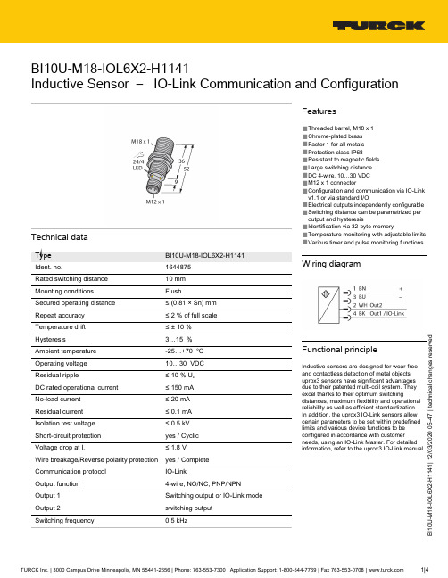
U -M 18-I O L 6X 2-H 1141 | 12/03/2020 05-47 | t e c h n i c a l c h a n g e s r e s e r v e dBI10U-M18-IOL6X2-H1141Inductive Sensor – IO-Link Communication and ConfigurationTechnical dataBI10U-M18-IOL6X2-H11411644875Rated switching distance 10 mm FlushSecured operating distance ≤ (0.81 × Sn) mm≤ 2 % of full scale ≤ ± 10 %3…15 %-25…+70 °C 10…30 VDC ≤ 10 % U ss DC rated operational current ≤ 150 mA ≤ 20 mA ≤ 0.1 mA ≤ 0.5 kV yes / Cyclic ≤ 1.8 V Wire breakage/Reverse polarity protection yes / Complete Communication protocol IO-Link4-wire, NO/NC, PNP/NPN Switching output or IO-Link mode switching output 0.5 kHzFeatures■Threaded barrel, M18 x 1■Chrome-plated brass ■Factor 1 for all metals ■Protection class IP68■Resistant to magnetic fields ■Large switching distance ■DC 4-wire, 10…30 VDC ■M12 x 1 connector■Configuration and communication via IO-Link v1.1 or via standard I/O■Electrical outputs independently configurable ■Switching distance can be parametrized per output and hysteresis■Identification via 32-byte memory■Temperature monitoring with adjustable limits ■Various timer and pulse monitoring functionsWiring diagramFunctional principleInductive sensors are designed for wear-free and contactless detection of metal objects.uprox3 sensors have significant advantages due to their patented multi-coil system. They excel thanks to their optimum switchingdistances, maximum flexibility and operational reliability as well as efficient standardization.In addition, the uprox3 IO-Link sensors allow certain parameters to be set within predefined limits and various device functions to be configured in accordance with customerneeds, using an IO-Link Master. For detailed information, refer to the uprox3 IO-Link manual.0U -M 18-I O L 6X 2-H 1141 | 12/03/2020 05-47 | t e c h n i c a l c h a n g e s r e s e r v e d Technical dataU -M 18-I O L 6X 2-H 1141 | 12/03/2020 05-47 | t e c h n i c a l c h a n g e s r e s e r v e dMounting instructionsAccessoriesBST-18B 6947214Mounting clamp for threaded barrel sensors, with dead-stop; material:PA6MW-186945004Mounting bracket for threaded barrel sensors; material: Stainless steel A21.4301 (AISI 304)BSS-186901320Mounting clamp for smooth and threaded barrel sensors; material:Polypropylene0U -M 18-I O L 6X 2-H 1141 | 12/03/2020 05-47 | t e c h n i c a l c h a n g e s r e s e r v e dWiring accessoriesDimension drawingTypeIdent. no.RKC4.4T-2/TEL6625013Connection cable, female M12, straight,4-pin, cable length: 2 m, sheathmaterial: PVC, black; cULus approval;other cable lengths and qualities available, see 。
Turck NI8-P18-Y1 S139 非漏水式水下感应传感器说明书

T 21:27:51+02:00Type code NI8-P18-Y1/S139Ident no.1072501Rated operating distance Sn 8 mm Mounting condition non-flushAssured sensing range ð (0,81 x Sn) mmCorrection factors St37 = 1; Al = 0.3; stainless steel = 0.7; Ms = 0.4Repeatability ð 2 % of full scale Temperature drift 10 %Hysteresis1…10 %Ambient temperature-25…+70 °C Output function 2-wire, NAMUR Switching frequency 1 kHzVoltageNom. 8.2 VDC Non-actuated current consumption ï 2.1 mA Actuated current consumptionð 1.2 mAApproval acc. toKEMA 02 ATEX 1090X Internal capacitance (C ) / inductance (L )150 nF / 150 µHDevice designationÉ II 2 G Ex ia IIC T6 Gb / II 1 D Ex ia IIIC T95 °C Da(max. U = 20 V, I = 60 mA, P = 200 mW)Design threaded barrel, M18 x 1Dimensions80 mmHousing material plastic, POM, black Material active area Plastic, POM, Black End capPlastic, PA Max. tightening torque housing nut 2 Nm Connection cableCable quality5.2 mm, blue, LifYY , PVC, 2 m Cable cross section 2 x 0.34 mm Vibration resistance 55 Hz (1 mm)Shock resistance 30 g (11 ms)Protection classIP68s ATEX category II 2 G, Ex zone 1s ATEX category II 1 D, Ex zone 20s SIL2 as per IEC 61508s Threaded barrel, M18 x 1s Plastic, POMs For underwater applications s Oil-resistantsProtection class IP68, 500 m water col-umns DC 2-wire, nom. 8.2 VDCsOutput acc. to DIN EN 60947-5-6 (NA-MUR)sCable connectionWiring diagramFunctional principleInductive sensors detect metal objects con-tactless and wear-free. For this, they use a high-frequency electromagnetic AC field that interacts with the target. Inductive sensors generate this field via an RLC circuit with a ferrite coil.We offer special versions for temperatures of -60 °C up to +250 °C.T 21:27:51+02:00Distance D 3 x B Distance W 3 x Sn Distance T 3 x B Distance S 1.5 x B Distance G 6 x Sn Distance N2 x Sn Diameter of the active area BØ 18 mmT 21:27:51+02:00AccessoriesType codeIdent no.DescriptionDimension drawingQM-186945102Quick-mount bracket with dead-stop; material: Chrome-plat-ed brass Male thread M24 x 1.5. Note: The switching dis-tance of proximity switches can be reduced by the use of quick-mount brackets.BST-18B 6947214Fixing clamp for threaded barrel devices, with dead-stop; ma-terial: PA6MW-186945004Mounting bracket for threaded barrel devices; material: Stain-less steel A2 1.4301 (AISI 304)BSS-186901320Mounting bracket for smooth and threaded barrel devices;material: PolypropyleneIM1-22EX-R 7541231Isolating switching amplifier, dual-channel; 2 relay outputs NO; input NAMUR signal; selectable ON/OFF mode for wire-break and short-circuit monitoring; adjustable signal flow (NO/ NC mode); removable terminal blocks; 18 mm width;universal voltage supply unitT 21:27:51+02:00Operating manual Intended useThis device fulfills the directive 94/9/EC and is suited for use in explosion hazardous areas according to EN60079-0:2012, -11:2012, -26:2007.Further it is suited for use in safety-related systems, including SIL2 as per IEC 61508.In order to ensure correct operation to the intended purpose it is required to observe the national regulations and directives.For use in explosion hazardous areas conform to classificationII 2 G and II 1 D (Group II, Category 2 G, electrical equipment for gaseous atmospheres and category 1 D, electrical equipment for dust atmo-spheres).Marking (see device or technical data sheet)É II 2 G acc. to Ex ia IIC T6 Gb acc. to EN60079-0 and -26 und É II 1 D Ex ia IIIC T95°C Da acc. to EN60079-0Local admissible ambient temperature -25…+70 °CInstallation / CommissioningThese devices may only be installed, connected and operated by trained and qualified staff. Qualified staff must have knowledge of protection classes, directives and regulations concerning electrical equipment designed for use in explosion hazardous areas.Please verify that the classification and the marking on the device comply with the actual application conditions.This device is only suited for connection to approved Exi circuits compliant to EN60079-0 and -11. Please observe the maximum admissible electrical values.After connection to other circuits the sensor may no longer be used in Exi installations. When interconnected to (associated) electrical equip-ment, it is required to perform the "Proof of intrinsic safety" (EN60079-14).When employed in safety systems to IEC 51408 it is required to assess the failure probability (PFD) of the complete circuitry.Installation and mounting instructionsAvoid static charging of cables and plastic devices. Please only clean the device with a damp cloth. Do not install the device in a dust flow and avoid build-up of dust deposits on the device.If the devices and the cable could be subject to mechanical damage, they must be protected accordingly. They must also be shielded against strong electro-magnetic fields.The pin configuration and the electrical specifications can be taken from the device marking or the technical data sheet.Special conditions for safe operationDue to normative regulations, the ATEX approval is only valid for application under atmospheric conditions between 0.8 and 1.1 bar. Underwater application, with higher pressure conditions, is therefore not covered by the approval. Above the water level Ex protection is applied to wiring of intrinsically safe circuits.service / maintenanceRepairs are not possible. The approval expires if the device is repaired or modified by a person other than the manufacturer. The most important data from the approval are listed.。
特克(Turck)产品说明书:BI10-P30SK-Y1X型号的导电感应传感器

T 14:23:30+02:00Type code BI10-P30SK-Y1X Ident no.40410Rated switching distance Sn 10 mm Mounting conditionsflushAssured switching distance ð (0,81 x Sn) mmCorrection factors St37 = 1; Al = 0.3; stainless steel = 0.7; Ms = 0.4Repeatability ð 2 % of full scale Temperature drift ð ± 10 %Hysteresis1…10 %Ambient temperature-25…+70 °C Output function 2-wire, NAMUR Switching frequency 0.5 kHzVoltageNom. 8.2 VDC Non-actuated current consumption ï 2.1 mA Actuated current consumptionð 1.2 mAApproval acc. toKEMA 02 ATEX 1090X Internal capacitance (C ) / inductance (L )150 nF / 150 µHDevice designationÉ II 2 G Ex ia IIC T6 Gb / II 1 D Ex ia IIIC T115 °C Da(max. U = 20 V, I = 20 mA, P = 200 mW)Construction Threaded barrel, M30 x 1.5Dimensions72 mmHousing materialPlastic, PA12-GF30Terminal chamber cover material plastic, UltemTerminal chamber housing material plastic, plastic, PA12-GF20Active area materialPlastic, PA Max. tightening torque housing nut 5 NmConnection terminal chamberClamping ability ð 2.5 mm Cable external diameter 4.5…8mm Vibration resistance 55 Hz (1 mm)Shock resistance 30 g (11 ms)Protection class IP67MTTF6198 years acc. to SN 29500 (Ed. 99) 40 °C Included in deliverycable gland; 2x plastic seals■ATEX category II 2 G, Ex zone 1■ATEX category II 1 D, Ex zone 20■SIL2 as per IEC 61508■Threaded barrel, M30 x 1.5■Plastic, PA12-GF30■DC 2-wire, nom. 8.2 VDC■Output acc. to DIN EN 60947-5-6 (NA-MUR)■Terminal chamberWiring DiagramFunctional principleInductive sensors detect metal objects con-tactless and wear-free. For this, they use a high-frequency electromagnetic AC field that interacts with the target. Inductive sensors generate this field via an RLC circuit with a ferrite coil.T 14:23:30+02:00Distance D 2 x B Distance W 3 x Sn Distance T 3 x B Distance S 1.5 x B Distance G6 x Sn Diameter of the active area BØ 30 mmT 14:23:30+02:00AccessoriesType code Ident no.DescriptionIM1-22EX-R7541231Isolating switching amplifier, 2-channel; 2 relay outputs; in-put NAMUR signal; selectable ON/OFF mode for wire-break and short-circuit monitoring; adjustable output mode (NO /NC mode); removable terminal blocks; width 18 mm; univer-sal power supply unitQM-306945103Quick-mount bracket with dead-stop; material: Chrome-plat-ed brass Male thread M36 x 1.5. Note: The switching dis-tance of proximity switches can be reduced by the use of quick-mount brackets.BST-30B 6947216Fixing clamp for threaded barrel devices, with dead-stop; ma-terial: PA6MW-306945005Mounting bracket for threaded barrel devices; material: Stain-less steel A2 1.4301 (AISI 304)BSS-306901319Mounting bracket for smooth and threaded barrel devices;material: PolypropyleneT 14:23:30+02:00Operating manual Intended useThis device fulfills the directive 94/9/EC and is suited for use in explosion hazardous areas according to EN60079-0:2012 and EN 60079-11:2012.Further it is suited for use in safety-related systems, including SIL2 as per IEC 61508.In order to ensure correct operation to the intended purpose it is required to observe the national regulations and directives.For use in explosion hazardous areas conform to classificationII 2 G and II 1 D (Group II, Category 2 G, electrical equipment for gaseous atmospheres and category 1 D, electrical equipment for dust atmo-spheres).Marking (see device or technical data sheet)É II 2 G and Ex ia IIC T6 Gb acc. to EN60079-0 and -26 und É II 1 D Ex ia IIIC T115°C Da acc. to EN60079-0Local admissible ambient temperature -25…+70 °CInstallation / CommissioningThese devices may only be installed, connected and operated by trained and qualified staff. Qualified staff must have knowledge of protection classes, directives and regulations concerning electrical equipment designed for use in explosion hazardous areas.Please verify that the classification and the marking on the device comply with the actual application conditions.This device is only suited for connection to approved Exi circuits compliant to EN60079-0 and -11. Please observe the maximum admissible electrical values.After connection to other circuits the sensor may no longer be used in Exi installations. When interconnected to (associated) electrical equip-ment, it is required to perform the "Proof of intrinsic safety" (EN60079-14).When employed in safety systems to IEC 51408 it is required to assess the failure probability (PFD) of the complete circuitry.Installation and mounting instructionsAvoid static charging of cables and plastic devices. Please only clean the device with a damp cloth. Do not install the device in a dust flow and avoid build-up of dust deposits on the device.If the devices and the cable could be subject to mechanical damage, they must be protected accordingly. They must also be shielded against strong electro-magnetic fields.The pin configuration and the electrical specifications can be taken from the device marking or the technical data sheet.In order to avoid contamination of the device, please remove possible blanking plugs of the cable glands or connectors only shortly before in-serting the cable or opening the cable socket.service / maintenanceRepairs are not possible. The approval expires if the device is repaired or modified by a person other than the manufacturer. The most important data from the approval are listed.。