Impinj 英频杰产品手册
OctaneSdkWorkbook_net英频杰(Impinj)读写器sdk使用手册

REV 1.0 2010-12-14 Proprietary and Confidential Copyright © 2010, Impinj, Inc.Impinj, Octane, and Speedway are eitherregistered trademarks or trademarks of Impinj, Inc.For more information, contact rfid_info@Octane 1.0 C# SDK Workbook2. Proprietary and Confidential Revision 1.0, Copyright © 2010 Impinj, Inc.ContentsIntroduction (4)Key Features (4)Getting Started with the Octane SDK (4)Pre Workshop Tasks (4)Task 1 Computer and Reader (4)Task 2–Unzip SDK (5)Task 3 – Install Visual C# 2010 Express (5)Task 4 – Exercise Examples (5)Task 5 Preparing for Exercises..................................................................................................7 Settings 10Query, Save, and Load Settings (11)Read Tags Synchronously (13)Read Tags Asynchronously (15)Read Tags Using Periodic Trigger (17)Read Tags Using GEN 2 Filter (18)Read User Memory (20)Read Serialized TID (22)Tag Access (24)Program EPC (25)Program User Memory (26)Kill Tags .....................................................................................................................................28 GPIO 30General Purpose Inputs (31)General Purpose Outputs (34)Subscribe, Test Power, and Thread (36)Subscribing to Reader Events (36)Power Ramp (37)Proper Threading Technique using Windows Presentation Format (WPF) (40)Notices: (45)Octane 1.0 SDK C# WorkbookRevision 1.0, Copyright © 2010 Impinj, Inc. Proprietary and Confidential 3.FiguresFigure 1 Speedway Reader Connections (5)Figure 3 Viewing Codin in C# OctaneSdk Sample (6)Figure 4 Visual Studio New Project Dialog Box (7)Figure 5 Visual Studio Adding References for OctandSdk (8)Figure 6 Visual Studio Add Reference Dialog Box (8)Figure 7 Adding Impinj.OctaneSdk Reference to C#.NET Program.cs ......................................... 8 Figure 8 EPC Gen 2 tag memory banks including EPC (1, or 01 in binary), TID (2, or 10) andUser (3 or 11). (13)Figure 9 Memory and features available on Monza 4 models (13)Figure 10 Impinj GPIO Connectivity Box (31)Figure 11 New WFP Project Dialog (40)Figure 12 WPF Code form (40)Figure 13 WPF Form Example (41)Octane 1.0 C# SDK Workbook4. Proprietary and Confidential Revision 1.0, Copyright © 2010 Impinj, Inc.IntroductionThe Octane SDK includes the core library that increases the usability of the Impinj Reader by simplifying the creation of Reader applications. It does this by acting as a wrapper for extracting, modifying, and the application of a Reader’s Low Level Reader Protocol (LLRP) settings. This provides high-level control over Reader settings, tag query, and tag-write operations which reduces the effort necessary to manipulate Reader functionality.Font Group Example StyleCode command Example 1 Reader =>File namesOctanesdk.zip Example codeusing Impinj.OctaneSdk; namespace QueryReaderSettingsKey FeaturesThe core library is delivered in multiple programming languages and is completed by a variety of documentation. On-Reader applications (C++ only) are written in the same manner as off-Reader applications, and all programming languages have a consistent implementation. The documentation is available in traditional online help .chm files, and also includes examples and templates:• Speedway Reader API• C#, C++ Linux• Examples, Templates, and Online HelpGetting Started with the Octane SDKThe Octane SDK is delivered in binary form as a DLL. Sample content is delivered as source code. Before the exercises in this workbook can be accomplished, the SDK must be unzipped. Visual Studio 2010 (VS2010) C# Express must be installed.Pre Workshop TasksTask 1 Computer and Reader1. Acquire a computer and Revolution Reader, and then network them together.2. To complete the tag access exercise, a Reader antenna and a few tags are required. Use Monza 4tags if available, but any EPC GEN 2 type will work.3. Connect the GPIO board or GPIO Connector Box to the multi-purpose DE15 connector, andconnect the Reader antenna to port 1 as shown in Figure 1 below.Octane 1.0 SDK C# WorkbookRevision 1.0, Copyright © 2010 Impinj, Inc. Proprietary and Confidential 5.Figure 1 Speedway Reader ConnectionsTask 2–Unzip SDK1. Octanesdk.zip contains the libraries, technical reference (Help text), and this Workbook.2. Unzip the file to a local directory.Note: This tutorial is included with the OctaneSdk. If you update to a new OctaneSdk version, check the OctaneSdk web page for a current version of this document.Task 3 – Install Visual C# 2010 ExpressTo install VS2010 C# Express, complete the following steps:1.Download and run the VS2010 installer, here:/express/downloads/#2010-Visual-CS .2. Restart your computer to complete the installation process. .3. Launch VS2010 and allow it to complete the one-time initialization process. This should take about 2 to 3 minutes.Task 4 – Exercise Examples1. From VS2010, select File, then Open Project.2. Select the /octane/cs/sdk/OctaneSdk.sln . file.3. Complete the file conversion. (This sample file was built using VS 2008.)Octane 1.0 C# SDK Workbook6. Proprietary and Confidential Revision 1.0, Copyright © 2010 Impinj, Inc.4. Right click on the desired program file (xxxxx.cs ) and then select View Code to view the code foreach project. See Figure 3.Figure 2 Viewing Codin in C# OctaneSdk Sample5. In the Solution Explorer, right click on Example1_QueryFeatures and then select Set As StartUpProject.6. Select Debug, and then Start Debugging. Enter your Reader’s name at the prompt and press enter.7. When done reviewing the Reader’s details, press any key to exit.Figure 1Exercise Example 1prompt: Example 1 Reader => {your reader’s name or IP address} output: Model Speedway R220 Software Version 4.4.1.3 Firmware Version 4.4.0.17 PCBA Version 270-001-003 FPGA Version 4.4.0.240 Regulator Region ETSI_EN_302_208_v1_2_1 Antennas 1:Connected 2:Unconnected 3:N/A 4:N/A prompt: Done => {press any key}Octane 1.0 SDK C# WorkbookRevision 1.0, Copyright © 2010 Impinj, Inc. Proprietary and Confidential 7.Note: The output from your Reader will be different from the above example, depending on the Reader model, region, and version information.8. Build and run the other examples to increase your skill using the SDK. Right click the Exampleproject, select Set As StartUp Project, and then Debug, and finally Start Debugging.Task 5 Preparing for Exercises1. For each exercise, create a new project by clicking File, and then New Project.2. Select Console Application as the template type in the New Project dialog3. Name the New Project something easy to remember. By default the project will be created in MyDocuments/Visual Studio 2010/Projects. See Figure 4.The project will be created in its ownfolder.Figure 3 Visual Studio New Project Dialog Box3. Select Solution Explorer and right click on the References folder, and then select Add Reference.Each time a project is created, the SDK libraries must be imported into the new project.Octane 1.0 C# SDK Workbook8. ProprietaryFigure 4 Visual S4. Browse to /OctaneSdk/Libr5. Click OK.Figure 5 Vis6. Type “using Impinj.OctaneIntellisense helps with thisFigure 6 Adding Impin7.Select File and then Save AOctane 1.0 SDK C# WorkbookRevision 1.0, Copyright © 2010 Impinj, Inc. Proprietary and Confidential 9.The new project is now prepared for the exercises.Octane 1.0 C# SDK Workbook10. Proprietary and Confidential Revision 1.0, Copyright © 2010 Impinj, Inc.SettingsSpeedway Readers have a wide range of capabilities. With so many capabilities, it requires configuration to reduce them to a manageable subset. The capabilities can be thought of as a programming language, or a set of tools waiting for a purpose. That purpose is defined by Reader settings. The settings are aprogram that describes what capabilities are used and how they behave. That means that the operation of Reader is critically dependent on the proper settings. The application depends upon the Reader. As a programmer, you must understand the settings and how they affect the Reader’s operation.The easiest way to get guaranteed success changing a Reader’s settings is to have the library catalog a default, or “best guess” settings object. Once that object is returned, the Reader settings can be changed with the default. Settings can be modified in code, written to disk, edited, and loaded back in. Settings are expressed as XML on disk, and also as a class .Query Services NameDescription QueryFactorySettingsDetermines most basic settings from the Reader’s capabilities and features. QuerySettingsIf the settings were changed, this returns current settings configuration. QueryFeatureSetDefinition of features that are available on the Reader. QueryStatus The current state of the Reader, antennas,and more.Command Services NameDescription ConnectConnects to a Reader allowing query and command services to transact. DisconnectAfter disconnect, no services are available until next connect. ClearSettingsDeletes the Readers settings and returns to the factory default settings. ApplySettings Replaces theReader’s current settings with the passed-in settings.Query, Save, and Load SettingsIn the following exercise you will connect to the Reader, save settings to an XML file, then edit and load the XML file to apply changes to the Reader settings.using System;using System.Collections.Generic;using System.Linq;using System.Text;using Impinj.OctaneSdk;namespace QueryReaderSettings{class Program{// Create an instance of the SpeedwayReader class.static SpeedwayReader Reader = new SpeedwayReader();static void DisplayCurrentSettings(){// Query the current reader settings and print the results.Console.WriteLine("Reader Settings");Console.WriteLine("---------------");Settings settings = Reader.QuerySettings();Console.WriteLine("Reader mode : {0}", settings.ReaderMode);Console.WriteLine("Search mode : {0}", settings.SearchMode);Console.WriteLine("Session : {0}", settings.Session);Console.WriteLine("Rx sensitivity (Antenna 1) : {0} dBm",settings.Antennas[1].RxSensitivityInDbm);Console.WriteLine("Tx power (Antenna 1) : {0} dBm",settings.Antennas[1].TxPowerInDbm);Console.WriteLine("");}static void Main(string[] args){try{// Connect to the reader.// Replace "SpeedwayR-xx-xx-xx" with your// reader's host name or IP address.Reader.Connect("SpeedwayR-xx-xx-xx");// Query the reader features and print the results.Console.WriteLine("Reader Features");Console.WriteLine("---------------");FeatureSet features = Reader.QueryFeatureSet();Console.WriteLine("Model name : {0}", features.ModelName);Console.WriteLine("Model number : {0}", features.ModelNumber);Console.WriteLine("Reader identity : {0}", features.ReaderIdentity);Console.WriteLine("Firmware version : {0}",features.FirmwareVersion);Console.WriteLine("Antenna count : {0}\n", features.AntennaCount);// Write the reader features to file.features.Save("features.xml");Revision 1.0, Copyright © 2010 Impinj, Inc. Proprietary and Confidential11.// Query the current reader status.Console.WriteLine("Reader Status");Console.WriteLine("---------------");Status status = Reader.QueryStatus();Console.WriteLine("Is connected : {0}", status.IsConnected);Console.WriteLine("Is singulating : {0}", status.IsSingulating);Console.WriteLine("Temperature : {0} degrees\n",status.TemperatureInCelsius);// Configure the reader with the factory deafult settings.Reader.ApplyFactorySettings();// Display the current reader settings.DisplayCurrentSettings();// Save the settings to file in XML format.Console.WriteLine("Saving settings to file.");Settings settings = Reader.QuerySettings();settings.Save("settings.xml");// Wait here, so we can edit the// settings.xml file in a text editor.Console.WriteLine("Edit settings.xml and press enter.");Console.ReadLine();// Load the modified settings from file.Console.WriteLine("Loading settings from file.");settings = Settings.Load("settings.xml");// Apply the settings we just loaded from file.Console.WriteLine("Applying settings from file.\n");Reader.ApplySettings(settings);// Display the settings again to show the changes.DisplayCurrentSettings();// Disconnect from the reader.Reader.Disconnect();}catch (OctaneSdkException e){Console.WriteLine("Octane SDK exception : {0}", e.Message);}catch (Exception e){Console.WriteLine("Exception : {0}", e.Message);}// Wait for the user to press enter.Console.WriteLine("Press enter when done.");Console.ReadLine();}}}12.Proprietary and Confidential Revision 1.0, Copyright © 2010 Impinj, Inc.Revision 1.0, Copyright © 2010 Impinj, Inc. Proprietary and Confidential13.There are three memory banks on an EPC GEN 2 tag that you need to know how to query: the Electronic Product Code (EPC), User Memory, and Tag Identification (TID).Figure 7 EPC Gen 2 tag memory banks including EPC (1, or 01 in binary), TID (2, or 10)and User (3 or 11).Note: the data locations in figure 8. Focus attention on the EPC. The actual EPC begins at word2 (or hex address 20). Prior to the EPC is the 16 bit Cyclic Redundancy Check or CRC (word 0)and the Protocol Control (or PC) word (word 1).The exercises in this section enable you to read the three memory banks using two different approaches: synchronously and asynchronously. You will also apply the feature sets of the SDK such as filters where only tags with specific data will respond and serialized TID (tag returns EPC and TID together using one command). Figure 8 shows the memory available for the various version of the Impinj Monza 4 tag IC.Figure 8 Memory and features available on Monza 4 modelsRead Tags SynchronouslyIn this exercise, you will configure the Reader so that observed tag data is stored in Reader memory and a report of all observed tags is sent only when commanded by the client application.using System;using System;using System.Collections.Generic;using System.Linq;using System.Text;using Impinj.OctaneSdk;namespace ReadTagsSync{class Program{// Create an instance of the SpeedwayReader class.static SpeedwayReader Reader = new SpeedwayReader();static void Main(string[] args){try{// Connect to the reader.// Replace "SpeedwayR-xx-xx-xx" with your// reader's host name or IP address.Reader.Connect("SpeedwayR-xx-xx-xx");// Remove all settings from the reader.Reader.ClearSettings();// Get the factory default settings// We'll use these as a starting point// and then modify the settings we're// interested inSettings settings = Reader.QueryFactorySettings();// Tell the reader to include the antenna number// in all tag reports. Other fields can be added// to the reports in the same way by setting the// appropriate Report.IncludeXXXXXXX property.settings.Report.IncludeAntennaPortNumber = true;// Wait until the tag query has ended// before sending the tag report.settings.Report.Mode = ReportMode.WaitForQuery;// Apply the newly modified settings.Reader.ApplySettings(settings);// Read tags for 5 secondsConsole.WriteLine("Reading tags...");TagReport tagReport = Reader.QueryTags(5);// Print out the results.foreach (Tag tag in tagReport.Tags){Console.WriteLine("EPC : {0} Antenna : {1}",14.Proprietary and Confidential Revision 1.0, Copyright © 2010 Impinj, Inc.tag.Epc, tag.AntennaPortNumber);}// Disconnect from the reader.Reader.Disconnect();}catch (OctaneSdkException e){Console.WriteLine("Octane SDK exception: {0}", e.Message);}catch (Exception e){Console.WriteLine("Exception : {0}", e.Message);}// Wait for the user to press enter.Console.WriteLine("Press enter when done.");Console.ReadLine();}}}Read Tags AsynchronouslyIn this exercise, you will configure the reader to report each tag to the client application as soon as it is observed. This is known as “asynchronous reporting”.using System;using System.Collections.Generic;using System.Linq;using System.Text;using Impinj.OctaneSdk;namespace ReadTagsAsync{class Program{// Create an instance of the SpeedwayReader class.static SpeedwayReader Reader = new SpeedwayReader();static void Main(string[] args){try{// Connect to the reader.// Replace "SpeedwayR-xx-xx-xx" with your// reader's host name or IP address.Reader.Connect("SpeedwayR-xx-xx-xx");// Remove all settings from the reader.Reader.ClearSettings();// Get the factory default settings// We'll use these as a starting point// and then modify the settings we're// interested inSettings settings = Reader.QueryFactorySettings();// Tell the reader to include the antenna numberRevision 1.0, Copyright © 2010 Impinj, Inc. Proprietary and Confidential15.// in all tag reports. Other fields can be added// to the reports in the same way by setting the// appropriate Report.IncludeXXXXXXX property.settings.Report.IncludeAntennaPortNumber = true;// Send a tag report for every tag read.settings.Report.Mode = ReportMode.Individual;// Apply the newly modified settings.Reader.ApplySettings(settings);// Assign the TagsReported handler.// This specifies which function to call// when tags reports are available.Reader.TagsReported += new EventHandler<TagsReportedEventArgs>(OnTagsReported);// Start reading.Reader.Start();// Wait for the user to press enter.Console.WriteLine("Press enter when done.");Console.ReadLine();// Stop reading.Reader.Stop();// Disconnect from the reader.Reader.Disconnect();}catch (OctaneSdkException e){Console.WriteLine("Octane SDK exception: {0}", e.Message);}catch (Exception e){Console.WriteLine("Exception : {0}", e.Message);}}static void OnTagsReported(object sender, TagsReportedEventArgs args){// This function is called asynchronously// when tag reports are available.// Loop through each tag in the report// and print the data.foreach (Tag tag in args.TagReport.Tags){Console.WriteLine("EPC : {0} Antenna : {1}",tag.Epc, tag.AntennaPortNumber);}}}}16.Proprietary and Confidential Revision 1.0, Copyright © 2010 Impinj, Inc.Read Tags Using Periodic TriggerThere may be cases where you want the reader to conduct ‘polling’ or examination for tags. During polling, the reader initiates a scan for tags for a specified period of time and then waits for a set period before scanning again. An example of this would be a “smart-shelf” application where the user does not need to know the instant that a tagged item is placed on, or removed from the shelf. Updating polling every 10 seconds is sufficient and reduces both network and RF congestion.There are a number of trigger types and settings available: refer to the SDK Quick Reference Guide or the SDK Compiled HTML Help File for more information.using System;using System.Collections.Generic;using System.Linq;using System.Text;using Impinj.OctaneSdk;namespace ReadTagsPeriodicTrigger{class Program{// Create an instance of the SpeedwayReader class.static SpeedwayReader Reader = new SpeedwayReader();static void Main(string[] args){try{// Connect to the reader.// Replace "SpeedwayR-xx-xx-xx" with your// reader's host name or IP address.Reader.Connect("SpeedwayR-xx-xx-xx");// Remove all settings from the reader.Reader.ClearSettings();// Get the factory default settings// We'll use these as a starting point// and then modify the settings we're// interested inSettings settings = Reader.QueryFactorySettings();// Tell the reader to include the antenna number// in all tag reports. Other fields can be added// to the reports in the same way by setting the// appropriate Report.IncludeXXXXXXX property.settings.Report.IncludeAntennaPortNumber = true;// Send a tag report for every tag read.settings.Report.Mode = ReportMode.Individual;// Reading tags for 5 seconds every 10 secondssettings.AutoStart.Mode = AutoStartMode.Periodic;settings.AutoStart.PeriodInMs = 10000;settings.AutoStop.Mode = AutoStopMode.Duration;settings.AutoStop.DurationInMs = 5000;// Apply the newly modified settings.Reader.ApplySettings(settings);Revision 1.0, Copyright © 2010 Impinj, Inc. Proprietary and Confidential17.// Assign the TagsReported handler.// This specifies which function to call// when tags reports are available.Reader.TagsReported += new EventHandler<TagsReportedEventArgs>(OnTagsReported);// Wait for the user to press enter.Console.WriteLine("Press enter when done.");Console.ReadLine();// Stop reading.Reader.Stop();// Disconnect from the reader.Reader.Disconnect();}catch (OctaneSdkException e){Console.WriteLine("Octane SDK exception: {0}", e.Message);}catch (Exception e){Console.WriteLine("Exception : {0}", e.Message);}}static void OnTagsReported(object sender, TagsReportedEventArgs args){// This function is called asynchronously// when tag reports are available.// Loop through each tag in the report// and print the data.foreach (Tag tag in args.TagReport.Tags){Console.WriteLine("EPC : {0} Antenna : {1}",tag.Epc, tag.AntennaPortNumber);}}}}Read Tags Using GEN 2 FilterThe Impinj Revolution Reader and Monza tags support what is known as GEN 2 filtering. There are two possible approaches to take when you only want to read certain tags based on their data. You can either use either EPC, User, TID, or a combination of these. One is to have all the tags in the read- zone and backscatter their data to the reader, then use filtering in the application layer (your program).The other method, which you will utilize here, is to configure the reader so that it commands only tags matching the filter to respond while the others will stay silent. This is useful when applied in the physical layer: only tags matching the filter will backscatter data and it can decrease the amount of RF and tag-to-tag interference.using System;18.Proprietary and Confidential Revision 1.0, Copyright © 2010 Impinj, Inc.using System.Collections.Generic;using System.Linq;using System.Text;using Impinj.OctaneSdk;namespace ReadTagsFiltered{class Program{// Create an instance of the SpeedwayReader class.static SpeedwayReader Reader = new SpeedwayReader();static void Main(string[] args){try{// Connect to the reader.// Replace "SpeedwayR-xx-xx-xx" with your// reader's host name or IP address.Reader.Connect("SpeedwayR-xx-xx-xx");// Remove all settings from the reader.Reader.ClearSettings();// Get the factory default settings// We'll use these as a starting point// and then modify the settings we're// interested inSettings settings = Reader.QueryFactorySettings();// Tell the reader to include the antenna number// in all tag reports. Other fields can be added// to the reports in the same way by setting the// appropriate Report.IncludeXXXXXXX property.settings.Report.IncludeAntennaPortNumber = true;// Send a tag report for every tag read.settings.Report.Mode = ReportMode.Individual;// Setup a tag filter.// Only the tags that match this filter will respond.// We're only going to use filter #1.settings.Filters.Mode = TagFilterMode.OnlyFilter1;// We want to apply the filter to the EPC memory bank.settings.Filters.TagFilter1.MemoryBank = MemoryBank.Epc;// Start matching at address 0x20, since the// first 32-bits of the EPC memory bank are the// CRC and control bits.settings.Filters.TagFilter1.BitPointer = 0x20;// Our filter is 16-bits long (the first word of the EPC).settings.Filters.TagFilter1.BitCount = 16;// Only match tags with EPCs that start with "3008"settings.Filters.TagFilter1.TagMask = "3008";// We want to include tags that match this filter.// Alternatively, we could exclude tags that// match the filter.settings.Filters.TagFilter1.FilterOp = TagFilterOp.Match;// Apply the newly modified settings.Reader.ApplySettings(settings);Revision 1.0, Copyright © 2010 Impinj, Inc. Proprietary and Confidential19.// Assign the TagsReported handler.// This specifies which function to call// when tags reports are available.Reader.TagsReported += new EventHandler<TagsReportedEventArgs>(OnTagsReported);// Start reading.Reader.Start();// Wait for the user to press enter.Console.WriteLine("Press enter when done.");Console.ReadLine();// Stop reading.Reader.Stop();// Disconnect from the reader.Reader.Disconnect();}catch (OctaneSdkException e){Console.WriteLine("Octane SDK exception: {0}", e.Message);}catch (Exception e){Console.WriteLine("Exception : {0}", e.Message);}}static void OnTagsReported(object sender, TagsReportedEventArgs args){// This function is called asynchronously// when tag reports are available.// Loop through each tag in the report// and print the data.foreach (Tag tag in args.TagReport.Tags){Console.WriteLine("EPC : {0} Antenna : {1}",tag.Epc, tag.AntennaPortNumber);}}}}Read User MemoryThe Impinj Monza 4 tags offer up to 512 bits of user memory. In this exercise you will query the user memory using exception handling best practices.using System;using System.Collections.Generic;using System.Linq;using System.Text;using Impinj.OctaneSdk;namespace ReadUserMemory{class Program20.Proprietary and Confidential Revision 1.0, Copyright © 2010 Impinj, Inc.{// Create an instance of the SpeedwayReader class.static SpeedwayReader Reader = new SpeedwayReader();static void Main(string[] args){try{// Connect to the reader.// Replace "SpeedwayR-xx-xx-xx" with your// reader's host name or IP address.Reader.Connect("SpeedwayR-xx-xx-xx");// Configure the reader with the factory deafult settings.Reader.ApplyFactorySettings();// Define how we want to perform the read.ReadUserMemoryParams readParams = new ReadUserMemoryParams();// Use antenna #1.readParams.AntennaPortNumber = 1;// No access password required for this tag.readParams.AccessPassword = null;// Start reading from the base of user memory (address 0).readParams.WordPointer = 0;// Read 32 words of user memory (512-bits).readParams.WordCount = 32;// Read the first tag we see.// Alternatively, we could choose a specific// tag by EPC or other identifier.readParams.TargetTag = null;// Timeout in 5 seconds if the read operation fails.readParams.TimeoutInMs = 5000;// Perform the read and check the results.ReadUserMemoryResult result = Reader.ReadUserMemory(readParams);if (result.ReadResult.Result == AccessResult.Success){Console.WriteLine("Tag read successful. Memory contents : {0}", result.ReadResult.ReadData);}else{Console.WriteLine("Error reading tag : {0}",result.ReadResult.Result);}// Disconnect from the reader.Reader.Disconnect();}catch (OctaneSdkException e){Console.WriteLine("Octane SDK exception: {0}", e.Message);}catch (Exception e){Console.WriteLine("Exception : {0}", e.Message);}。
杰基国际产品说明书

Pin AssignmentsDB-25 and DB-9 Pin AssignmentsRJ-45 Pin Assignments for 10-Pin and 8-Pin RJ-45 ConnectorsRefer to the Digi CD for more detailed cabling information or visit for more information.Digi, the Digi Connectware logo, AccelePort, and Digi Neo are trademarks or registeredtrademarks of Digi International in the United States and other countries. All other brandand product names are trademarks of their respective holders.© Digi International Inc., 2001, 2002, 2003 All Rights Reserved; Information in this document is subject to change without notice and does not represent acommitment on the part of Digi International.Digi provides this document “as is,” without warranty of any kind, either expressed orimplied, including, but not limited to, the implied warranties of fitness or merchantabilityfor a particular purpose. Digi may make improvements and/or changes in this manual or inthe product(s) and/or the program(s) described in this manual at any time.This product could include technical inaccuracies or typographical errors. Changes are peri-odically made to the information herein; these changes may be incorporated in new editionsof the publication.Digi NeoPCI Host AdaptersEIA-232Hardware InstallationGuideIntroductionA Digi Neo™ adapter easily expands the number of EIA-232 portsavailable on your computer, allowing you to cable additional peripheraldevices, such as modems, terminals or serial printers, directly to yourcomputer.The Digi Neo 2 port adapter has two connectors (DB-9 or RJ-45) on theadapter to provide peripheral port connections.Digi Neo 4 and 8 port adapters are equipped with an HD-68 connector towhich a special Digi connector assembly is attached to provide theperipheral port connections. There are seven different connector assem-bly options available to use with Digi Neo 4 and Neo 8 adapters:•RJ-45 Connector Box•DB-25 Connector Box (male connectors)•DB-9 Connector Box (male connectors)•DB-25 Fan-out Cable (male or female connectors)•DB-9 Fan-out Cable (male or female connectors)This installation guide describes how to plan your setup and install a DigiNeo adapter.Signal Description DB-25 Pin DB-9 Pin GND Chassis Ground Shell Shell TxD Transmitted Data23 RxD Received Data32 RTS Request To Send47CTS Clear To Send58DSR Data Set Ready66SG Signal Ground75DCD Data Carrier Detect81DTR Data Terminal Ready204RI Ring Indicator229Signal Description Pin # (of 10)Pin # (of 8)RI Ring Indicator1N/ADSR Data Set Ready2†1†RTS Request To Send32GND Chassis Ground43TxD Transmitted Data54RxD Received Data65SG Signal Ground76CTS Clear To Send87DTR Data Terminal Ready98DCD Data Carrier Detect10N/A† DSR (Pin 2 on a 10 pin connector, Pin 1 on an 8 pin connector)can be swapped with DCD by using the ALTPIN configurationoption. ALTPIN reverses the position of these two signals in 10pin connectors and allows DCD to be used instead of DSR on an8 pin connector.Consult the driver documentation for how to do this in yourspecific operating system.91001071_BStep One: Plan Your SetupA Digi Neo adapter can be set up in a variety of ways. Before you start your installation, consider the following:Number of Components. You can connect two peripheral devices to a Digi Neo 2, up to four peripheral devices to a Digi Neo 4, and eight periph-eral devices to a Digi Neo 8 adapter. Up to four Digi Neo adapters may be installed in a computer.Construction of Cables. To achieve the greatest reliability over distance, cables should be:•Shielded, low capacitance, and preferably designed specifically for serial data transmission.•Grounded at both ends of the cable.•Routed away from noise sources such as generators, motors and fluorescent lights.Cable Connections. Before beginning the installation, verify that you have the appropriate Digi connector assemblies (fan-out cables or connec-tor box assemblies). Fan-out cable and connector box options aredescribed in detail in a separate Cable Usage Guide.You will also need a cable for each peripheral that you will be attach-ing to the connector assembly. The connector type that you need at either end of the peripheral cable depends on the type of Digi connec-tor assembly that you use and the connector on the peripheral.Digi connector assemblies are available with RJ-45, DB-25 or DB-9 connectors. You will need to be sure that you have cables of the cor-rect length and with the right connectors to properly attach thedevices you want to use.Additional information about the Digi Neo adapter, such as specifications and cabling details, is provided on the Digi CD which is packaged with the adapter.Step Two: Install the Neo AdapterCAUTION! To guard against damage to the adapter due to electrostaticdischarge (ESD), do not remove the adapter from its protective packag-ing until you have grounded yourself to the computer chassis (see step 4,below).1.Shut down your computer in the manner recommended for your oper-ating system.2.Unplug power from the computer.3.Remove the computer’s cover.4.Touch the computer chassis to equalize any static potential betweenyourself and the computer. This will help prevent damage to theadapter due to electrostatic discharge.5.Locate an available PCI slot in your computer and remove the slotplate.6.Remove the adapter from its protective packaging.7.Write down the serial number of the adapter in the space providedbelow.8.Insert the adapter into the slot and screw the endplate to the computerchassis. The endplate must be screwed into the computer chassis toremain in compliance with Part 15 of FCC rules.9.Replace the computer’s cover.10.Attach the peripheral interconnect cable(s) to the adapter.CAUTION: Many SCSI adapters use the same HD-68 connector type asthe Neo adapter. Do not plug SCSI devices into the Digi connector, anddo not plug Digi peripheral cables into SCSI adapters.Serial Number: ________________________Step Three: Install Peripheral CablingYou can connect modems, terminals, serial printers, or any other standardEIA-232 device to a Digi Neo adapter using a cable between the periph-eral and the Digi connector assembly.On the peripheral end of the cable, the connector you must have dependson the requirements of the peripheral. The Digi end of the cable must beequipped with the connector type that mates with the connectors on theDigi connector assemblyIn the case of the 2 port product, the cables are connected directly to theadapter’s end-plate.。
英频杰(Impinj) R220

适用于要求较低的应用环境。不支持R420那样的最大生产模式,包括Max Throughput FM0, Hybrid, Max Miller和自动设置单个阅读器
· 美国, 加拿大以及其他符合US FCC Part 15的地区 · 欧洲以及其他符合 ETSI EN 302 208 v1.2.1 无 LBT 地区 · Brazil, 香港, 印度, Uruguay, 越南 · 正在申请认证的地区—澳大利亚, 中国大陆, 马来西亚, 新加坡, 台湾地区,与泰国 2个专为Impinj阅读器天线优化的高性能的单极化天线端口 (RP TNC) · +10.0 to +30.0 dBm (PoE) · +10.0 to +32.5 dBm1 (外接通用电源) 注1: Speedway Revolution 需要专业人士安装,只能配对Impinj认可的天线, FCC Part 15.247 规约下.不超出 36 dBm EIRP ,其他区域有相似规定。查阅安装与操作手册以了解更多. -82 dBm
10 dB
EPCglobal 低级读写器协议 (LLRP) v1.0.1
10/100BASE-T auto-negotiate (full/half) with auto-sensing MDI/MDX for autocrossover (RJ-45)
· Sierra Wireless AirLink PinPoint XT (CDMA 或 GSM 链接(带 GPS 数据)) · Sierra Wireless AirLink Raven XT (CDMA 或 GSM 链接) (* 可从Impinj授权的合作伙伴获取)
最大接收灵敏度82dbm最大返回损耗10db应用界面epcglobal低级读写器协议llrpv101网络链接10100basetautonegotiatefullhalfautosensingmdimdxautocrossoverrj45蜂窝网络链接sierrawirelessairlinkpinpointxtcdmagsm链接带gps数据sierrawirelessairlinkravenxtcdmagsm链接可从impinj授权的合作伙伴获取ip地址配置dhcp静态or或使用组播域名系统mdns的链路本地地址lla时间同步网络时间协议ntp管理界面使用系列管理控制台端口的impinjrshell管理控制台telnet或sshsnmpv2mibii系统记录可靠的固件升级可扩展的升级机制可以按计划升级多个读写器apple商品uhf芯片rfid系统rfid配件连接器复用器切换器分安装支架会员管理超高频系列一体机系列通道系列持机系列uhf天线高频系列高频一体系列高频手持uhf电子标签inlaylabel智能卡类金属系列异型类标签hf电子标签高频inlay标签智能卡系抗金属系列lf系列产品读卡器系列电子标签系24g微波系列热销推荐impinjindyr2000rfid标签芯片您浏览过的商品清除列表查看所有空闲典型ldcpoe30dbm电源适配器30dbm电源适配器325usbflashdriveimpinjweb管理界面管理控制台rs232usingstandardciscostylemanagementcabledb9波特率
nRF24L01P产品说明书V1.0资料
nRF24L01+单片机2.4 GHz收发器产品说明书v1.0主要功能:全球通用的2.4 GHz ISM波段操作250kbps, 1Mbps and 2Mbps空中数据传输速率超低功率运行发射功率为0dBm(1.0mW)时,发射电流为11.3mA2Mbps空中数据传输速率,接收电流为13.5mA掉电电流为900nA待机-I电流26μA片内电压调整器1.9至3.6V电源供电范围增强型ShockBurst TM自动数据包处理自动包数据包事务处理6数据通道的MultiCeiver TM与nRF24L01嵌入式兼容空中数据速率250kbps 和1Mbps,与nRF2401A,nRF2402, nRF24E1和nRF24E2兼容低BOM成本±60ppm 16MHz晶振容许5V输入紧凑的20引脚4x4mm QFN封装应用无线 PC外围设备鼠标,键盘和遥控器三和一桌面捆绑先进的媒体中心遥控器网络电话耳机游戏控制器蓝牙模块运动手表和传感器消费电子产品射频遥控器家庭和商业自动化超低功率无线传感器网络RFID 射频识别资产跟踪系统玩具免责条款北欧半导体ASA有权做出随时更改,提高产品可靠性、功能或设计,不另行通知。
北欧半导体ASA不承担由于应用程序或使用任何所述产品或电路引起的责任。
所有应用程序的信息咨询,不构成说明书的组成部分。
极限值超过一个或多个限制的应力可能会造成设备永久性损坏。
这些应力等级只有在这样或那样的操作环境中提出,在规范中没有给出。
长时间暴露在限制值附近可能会影响设备的可靠性。
生命支持应用这些产品并非为因故障会引起人身伤害的维生装备,设备或系统设计的。
北欧半导体ASA客户使用或出售这些产品,他们将自担风险并同意完全赔偿北欧半导体ASA因使用不当或销售行为造成任何损害。
详细联系方式访问www.nordicsemi.no进入北欧半导体销售办事处和全世界的分销商网站总办公室:Otto Nielsens vei 127004 Trondheim电话: +47 72 89 89 00传真: +47 72 89 89 89www.nordicsemi.no写作惯例本产品规范遵循一套排版规则,文档一致,容易阅读。
PLG微型热敏打印机开发手册V1.3

PLG微型热敏打印机开发手册V1.3目录第一章概述----------------------------------------------------------------------------------------1第二章通讯接口-----------------------------------------------------------------------------------22.1RS-232接口--------------------------------------------------------------------------------22.2红外接口-----------------------------------------------------------------------------------3第三章指令说明------------------------------------------------------------------------------------43.1打印控制指令-----------------------------------------------------------------------------------53.1.1ESC@------------------------------------------------------------------------------------53.1.2LF---------------------------------------------------------------------------------------53.1.3CR---------------------------------------------------------------------------------------53.1.4FF---------------------------------------------------------------------------------------53.1.5ESC J n----------------------------------------------------------------------------------63.1.6ESC d n----------------------------------------------------------------------------------6 3.2字符参数设置指令-------------------------------------------------------------------------------63.2.1ESC!N----------------------------------------------------------------------------------63.2.2ESC M n----------------------------------------------------------------------------------73.2.3GS!n-----------------------------------------------------------------------------------73.2.4ESC-n----------------------------------------------------------------------------------83.2.5ESC E n----------------------------------------------------------------------------------83.2.6ESC G n----------------------------------------------------------------------------------83.2.7GS B n-----------------------------------------------------------------------------------8 3.3打印排版设置指令-------------------------------------------------------------------------------93.3.1ESC$nL nH------------------------------------------------------------------------------93.3.2ESC2------------------------------------------------------------------------------------93.3.3ESC3n----------------------------------------------------------------------------------93.3.4ESC\nL nH------------------------------------------------------------------------------93.3.5ESC SP n--------------------------------------------------------------------------------10 3.4图形打印指令----------------------------------------------------------------------------------103.4.1ESC*m nL nH d1…dk--------------------------------------------------------------------103.4.2GS'------------------------------------------------------------------------------------11 3.5条形码打印命令--------------------------------------------------------------------------------123.5.1GS k------------------------------------------------------------------------------------123.5.2GS h n----------------------------------------------------------------------------------123.5.3GS w n----------------------------------------------------------------------------------123.5.4GS H n----------------------------------------------------------------------------------133.5.5GS f n----------------------------------------------------------------------------------13 3.6汉字打印指令----------------------------------------------------------------------------------133.6.1FS&------------------------------------------------------------------------------------143.6.2FS.------------------------------------------------------------------------------------14附录----------------------------------------------------------------------------------------------15 A英文字符集-----------------------------------------------------------------------------15 B预印刷黑标说明-------------------------------------------------------------------------15第一章概述PLG微型热敏打印机是一款便携式热敏打印机,使用可充电电池供电,可带机充电,使用RS-232接口和IrDA红外接口,可用于各种仪器仪表、手持设备的数据打印。
英杰功率控制器通讯板说明书

PB20 通讯板 PROFIBUS
一 说明
PB20选件板通过PROFIBUS协议将装置与PROFIBUS网络连接起来。 PB20通讯板具备两个PROFIBUS接口,分别为1#口与2#口,通过板上拨码开关设置其地址与PPO模 式。当设置为不同地址时,可将两通讯接口接入同一PROFIBUS网络或不同网络;当地址设置相同时, 两通讯接口可在冗余的网络中运行。 订货时可指定为单通讯或双通讯:单通讯(PB20-1)、 双通讯(PB20-2)。
7.51 7.52 7.53 7.54 7.55 7.56 7.57 7.58 7.59 7.60 控制器单元 1#读对应
(5.51) (5.52) (5.53) (5.54) (5.55) (5.56) (5.57) (5.58) (5.59) (5.60) 控制器单元 2#写对应
7.61 7.62 7.63 7.64 7.65 7.66 7.67 7.68 7.69 7.70 控制器单元 2#读对应
通过 PB20 板上拨码开关设置通讯地址与 PPO 类型。 拨码值以二进制表示,当拨码在 ON 方向时表示 1,拨码在下方(数字方向)时表示 0。 地址拨码:地址拨码开关左边为二进制高位,右边为二进制低位;图 4 中 SW1 拨码为 00000011,
转换成十进制表示 3,因此 1#通讯口地址为 3。 PPO 拨码:拨码开关 SW2 和 SW4 第 2、3、4 位用二进制分别表示 1#与 2#通讯口的 PPO 类型。
PB20 通讯板 PROFIBUS 使用说明书
英杰电气有限公司为客户提供全方位的技术支持, 客户可与就近的英杰办事处或代理商联系。 内容如有改动,恕不另行通知!
目录
一 说明........................................................................................................................................................................1 二 技术参数................................................................................................................................................................1 三 安装........................................................................................................................................................................2 四 连接........................................................................................................................................................................2 五 地址与PPO类型设置............................................................................................................................................3 六 PROFIBUS-DP.....................................................................................................................................................4 七 参数区(PKW)读写 ..........................................................................................................................................6 八 过程数据区(PZD)读写....................................................................................................................................7 九 GSD文件 ...............................................................................................................................................................9 十 冗余功能................................................................................................................................................................9
JK Audio innkeeper LTD Digital Hybrid ii 用户手册说明书
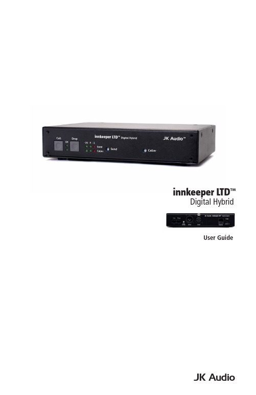
JK AudioUser Guideinnkeeper LTD ™Digital Hybridii innkeeper LTD™ Digital HybridThank YouThank you for purchasing a JK Audio innkeeper LTD Digital Hybrid. Please read this guide for instructions on setting up and using your new product.Getting AssistanceIf you have technical or application questions: Call us at:815-786-2929 Email us at:*******************Or check out our FAQ section for answers to common questions.Warnings & Safety Precautions• Read and keep these instructions.• Follow all instructions.• Clean only with a soft dry cloth.• Refer all servicing to qualified service personnel.• Heed all warnings.Warning: Do not install near any heat sources such as radiators, heat registers, stoves, or other apparatus (including amplifiers) that produce heat.Warning: Do not defeat the safety purpose of the three-prong grounding type plug. If the provided plug does not fit into your outlet, consult anelectrician for replacement of the obsolete outlet.Warning: Do not use this unit if the electrical power cord is frayed or broken. The power cord should be routed so that it is not likely to bewalked on or pinched by items placed upon or against it.To reduce the risk of fire: Use only No. 26 AWG or larger telecommunication line cord.To reduce the risk of fire or electric shock: Do not expose thisapparatus to rain or moisture. WelcomeContents iiiContentsLimited WarrantyThe innkeeper LTD is covered by a 1 year warranty to be free from defective workmanship and materials. To obtain service, contact JK Audio by phone or email for return authorization. Once authorized, you will carefully pack and ship the faulty product and all accessories to us. You will pay for shipping to us and we will pay for return back to you.This warranty does not cover damages due to accident, weather, fire, flood,earthquake, misuse, unauthorized repairs or modifications, or damages occurred in shipping, only defective workmanship or materials.There are no expressed or implied warranties which extend beyond the warranty here made.16 bit DSP TechnologyAuto-Answer (Switchable On/Off)Proprietary Auto Null Algorithm (50 dB null)Send XLR Line InputCaller XLR Line Output Front Panel Off-Hook LEDGuest Module 1 Remote Control Jack Send and Caller Signal Level LEDs Send and Caller Volume Controls Rack MountableFeaturesUniversal Power Supply with Detachable Cord RJ11 Phone CordWhat’s in the Box?Featuresiv innkeeper LTD™Digital HybridOverview Introducing the innkeeper LTD™Innkeeper LTD allows you to send line level signals into the phone line while maintaining excellent separation between your voice and the caller. Thebalanced XLR output jack contains only the caller’s voice, making this the perfect companion to mixers, consoles, and PA systems that demand talk show qualityaudio from a phone line.The digital hybrid connects audio signals to a standard analog phone linewithout the transmit/receive crosstalk common to analog hybrids. Its DigitalSignal Processor (DSP) continuously monitors both the phone line and audiosignals to deliver excellent separation. This proprietary, dual-convergence echo canceller algorithm can achieve separation typically exceeding 50 dB withoutany setup and without sending a noise burst down the line. While this may sound complicated, it’s all done automatically during every call.Ready to go?The innkeeper LTD controls and connectors are clearly marked and ready for operation. If this is your first exposure to a hybrid, we suggest that you read theentire manual to allow you to take advantage of all these features.Any Questions?Before you pick up the phone... Please thumb through the rest of this manual.You might find those deep technical questions are covered on later pages.Overview1Getting to Know Your innkeeper LTD1324567Controls & Indicators1. Call ButtonTakes the line off-hook; press this button to answer a call or you can direct acall from your aux phone through the hybrid.2. OH LEDLit when you are on line with a call (off-hook).3. Drop ButtonPress this button to drop (hang up) a call.4. Signal LEDsSend LEDs represent the signal level going out to the telephone line.Caller LEDs represent the signal level coming from the phone line,after the DSP.5. Send LevelAdjusts the signal that you are sending down the telephone line.6. Caller LevelAdjusts the level of the incoming caller’s audio as it is going out the outputjacks.7. Power LEDLit when unit is plugged in and receiving power.2innkeeper LTD™Digital HybridGetting to Know Your innkeeper LTD 1324567 ArrayInputs & Outputs1. Phone LineConnect to a standard, single line, analog telephone line.2. Aux PhoneConnect a single line analog telephone for call setup / dialing, or producercall screening.3. Auto AnswerWhen enabled, innkeeper LTD automatically answers an incoming call andthen disconnects after the caller hangs up. Auto answer will occur on thefirst ring.4. Caller OutputMale balanced XLR output contains only the callers voice.5. Send InputFemale balanced XLR input for signals going into the phone line.6. Remote Control Jack8-pin modular RJ-45 jack for connection to the optional JK Audio GuestModule 1 Remote Keypad or your broadcast console switch contacts (seepage 7). Do not connect this jack to your computer network port.7. Power JackFor connection only to the supplied 9VDC regulated power supply.Controls & Indicators3Getting ConnectedConnecting to a Single Line Phone1. Connect the supplied RJ-11 phone line cable between the jack marked<Line> and your wall jack. Be sure this jack supports standard single lineanalog telephone operation.2. You may want to connect an auxiliary telephone to the innkeeperLTD <Phone> jack so you can dial out and set up calls, or use the<Auto-Answer> feature to answer incoming calls.Connecting to a Mixer (Mix Minus Caller)Note: A mix-minus signal is an audio signal that contains a mix of your local microphones plusany other audio, minus the Caller’s own voice. Sending the Caller’s audio back to the innkeeper LTD will cause an echo, or feedback.3. Connect the innkeeper LTD <Caller> output to any Line input on the mixer.4. Connect your microphone(s) to the mic inputs on your mixer.5. Connect the mixer’s Mix-Minus bus or Aux Send output (this may be labeledFX or Mon but any Aux bus will work) to the <Send> input on innkeeper 1rx.Set the innkeeper 1rx <Mic/Line> switch to the Line position.6. If your mixer doesn’t have a mix-minus bus: Whichever input channelyou have the <Caller> connected to, turn the corresponding Aux control tominimum. All Aux controls for other channels should be set for audio sentto the phone line. Each Aux Send bus is completely separate from all otheroutputs, so these Aux controls will not affect what is heard on the Mainoutputs or on any other Aux buses.Tip: Using an Aux Send bus that is Pre-Fader allows you to control the levels of eachchannel to the main output without affecting what is sent to the phone line.7. Connect your headphones to the mixer.8. Use Main Outputs to send audio to recording device or broadcastingequipment inputs.4innkeeper LTD™Digital HybridCompleting Setup9. Connect the supplied DC power supply to the back of the innkeeper 1rx and then to an AC power outlet.This device should be connected to an adequate surge protectivedevice at all times both for the power connector and for thetelephone line to avoid damage from lightning or electrical surges.10. Adjust the <Send> level controls so that you consistently light the green -20 dB and -9 dB and rarely light the red -3 dB peak Send LED. Theseflashes should occur only during loud speech bursts. If the red LED stayslit for extended periods you can assume that much of your speech is beingclipped or distorted. Set the <Caller> control for good recording level of thecaller audio at the output jack.5Getting ConnectedOperationAuxiliary TelephoneAn auxiliary telephone provides you with an easy way to dial out or set up your calls. innkeeper LTD will disconnect the auxiliary telephone when you press the <Call> button. If you need to take the call back on the aux telephone, simply pick up the telephone handset before the innkeeper LTD’s <Drop> button is pressed.To use an auxiliary phone equipped with a “Hold” feature to place or screen acall, first set up the call and place the call on hold. When you are ready to take the call on Innkeeper LTD, press the <Call> button on the innkeeper LTD andyour telephone will automatically release the hold.Your phone will operate as a normal telephone anytime you are in Drop mode.Leaving the hybrid connected between the wall jack and your telephone will not affect normal use of your phone. Audio will only pass through the hybrid whenyou press the <Call> button.Optional Jumper SettingsIf the incoming Caller level is too high and peaking the red -3 dB LED, youmay need to change the setting of an internal jumper. Disconnect power fromthe hybrid and remove the cover of the innkeeper LTD to locate Jumper 1. The default position for this jumper is closed (covering both pins). Changing thejumper to the open position (either remove the jumper or cover just one pin) will provide 6 dB attenuation of the incoming audio signal.Auto-AnswerThe <Auto-Answer> feature will answer on the first ring. When <Auto- Answer> is enabled, you can still make calls manually using the <Call> button.When finished, you can either drop the call manually or allow the call toAuto-Disconnect. innkeeper LTD will look for a CPC disconnect signal from the phone company to determine when a call has disconnected. This can take up toa minute.6innkeeper LTD™Digital Hybrid7Remote ControlRemote Control Remote Control JackThe RJ-45 jack on the back of the innkeeper LTD provides connection to anoptional JK Audio Guest Module 1 remote control, or it can be wired to the switch contacts on your broadcast console. Do not connect this jack to the network port on your computer.RJ-45 Pinout :1: Ground 2: Call / Drop Control (main control pin) 3: Ring / OH LED 4: DTMF Input 5: +4.3 VDC 6: Reserved 7: Reserved 8: ReservedTo take innkeeper LTD off-hook , momentarily connect pin 2 to pin 5 (power) through a 100 ohm ¼ watt resistor.To release (Drop) the phone line , momentarily connect pin 2 to pin 1 (ground) through a 100 ohm 1/4 watt resistor.Pin 3 contains a 4.3 VDC, 40 mA current limited output to drive a signal LED. We suggest adding a 200 ohm ¼ watt resistor in series with an LED connected to ground.Pin 5 supply output is current limited to 100 mA with a resettable fuse for use with the Guest Module and pin 2 connections. Do not attempt to power additional circuitry from this pin.Guest Module 1 (Sold Separately)This convenient device gives you remote access to the on-hook/offhook and dial features of the innkeeper LTD. The <Call> button will flicker when a call comes in and will stay lit while a call is present. When you dial out using the Guest Module 1 keypad, the tones are sent directly down the phone line, and do not come back blasting in your ear. Product sold separately.Guest Module 1 Features:• Ring and Call LED• Call and Drop Buttons• DTMF Keypad• Keypad Disable Switch• Remote Powered8innkeeper LTD™ Digital Hybrid Technical Information P h o n e L i n e J a c k A u x P h o n e J a c kS e n d I n p u tInput Impedance / LevelBalanced Female XLR:20k ohms / 50 mV RMS; -4 dBu nom.; OutputBalanced Male XLR:200 ohms / 500 mV RMS; -4 dBu nom.; +14 dBu max; Caller OnlyMiscPhone Line:RJ11CRemote Jack:RJ45Ringer:0.8B RENIsolation:1500 VACFrequency Response:Telephone Side 200 Hz-3.6 kHzPower:120-240 VAC Power SupplySize: 7.6” x 5.3” x 1.5” (20 x 14 x 4 cm)Weight: 2.7 lbs (1.2 kg)SpecificationsTechnical Information9Technical InformationFAQs1. Does the innkeeper LTD send a burst or beep downthe phone line at the beginning of each call like ourcurrent hybrid?No. Innkeeper LTD uses the actual transmit signal to evaluate the phone lineand tune its algorithm. As you begin to speak, innkeeper LTD is hard at workcanceling your voice from the Caller Output jack. Within milliseconds yourvoice is reduced into the noise floor.2. Can I use the innkeeper LTD on a VoIP line?Many VoIP lines have an analog telephone adapter you can connectyour telephone to. If you can use any standard analog telephone, theninnkeeper LTD should work great. If you have to use a specific telephone,you should consider our AutoHybrid IP2 VoIP hybrid or Innkeeper PBX digitalhybrid instead.3. The caller’s audio is too high and is always distorted eventhough I have the Caller level control turned down low. Whatelse can I do?The Receive LED meter will indicate the level of audio coming in from thetelephone line, just after it passes through the DSP. The Caller level controlwill only set how much of that audio will be sent to the output jack, and willhave no effect on the LED meter. If your incoming audio level is unusually hotand already peaking the –3 dB LED, there is a jumper on the circuit boardyou can change to attenuate the incoming audio. Please see page 6 formore information.4. I have my new innkeeper LTD connected to the phone jack inmy office. Why does it keep dropping the calls as soon as Itry to connect it?The telephone jack in your office is very likely for a multi-line phone system.The jack may look like a standard phone jack, but it is wired differently andmay carry voltage on different pins which could cause serious damage to yourhybrid. Innkeeper LTD should only be connected to a single, analog phoneline. Check with the telephone specialist in your building for the possibility ofgetting an analog line for your innkeeper LTD.5. I have my new innkeeper LTD connected to an analogextension in my office. It will auto answer just fine but doesnot auto disconnect after the call has ended. How can I makeit auto disconnect properly?A PBX phone system can be programmed to provide an analog line. Checkwith the telephone specialist in your building for the possibility of resetting thecharacteristics of your analog line to provide an appropriate CPC disconnectsignal.10innkeeper LTD™Digital HybridManufacturer’s Name:Manufacturer’s Address:JK Audio, Inc.1311 E 6th StreetSandwich, Illinois 60548 USADeclares that the product:Product Name:Model Numbers:innkeeper LTD Digital Hybridinnkeeper LTDConforms to the following Product Specifications:Safety: ESD:Emissions:Telecom:AS/NZS 60950.1:2003CAN/CSA-C22.2 No. 60950-01-03UL Standard 60950-01 1st editionEN 55024:1998; EN 61000-3-2; EN 61000-3-3EN 55022:1998AS/NZS CISPR 22 (2002)FCC Part 15, Subpart BICES-003AS/ACIF S002:2005FCC CFR 47, Part 68TIA968 A-1, A-2, A-4The product herewith complies with the requirements of the following Directives and carries the CE marking accordingly:LVD 2006/95/EC (Safety)R&TTE 1999/5/EC (Telecom)EMC 89/336/EEC (EMC)RoHS Directive 2015/863The Technical File containing supporting documentation is maintained at:JK Audio, Inc (Corporate Headquarters)Compliance Manager1311 E 6th StreetSandwich, Illinois 60548 USA815-786-2929 phone815-786-8502 faxDeclaration of Conformity 11Declaration of ConformityDeclaration of ConformityFCC RegistrationFCC RegistrationYour new JK Audio product has been registered with the Federal CommunicationsCommission (FCC). This product complies with the standards in Part 68 of theFCC rules.1. Connection and use with the nationwide telephone networkThe FCC requires that you connect this telephone equipment to the national telephone network through a USOC RJ-11C modular telephone jack. This equipment may not be used with Party Line Service or Coin Telephone Lines. This equipment is hearing aidcompatible.2. Information for the telephone companyUpon request from your local telephone company, you are required to provide thefollowing information:A. The “line” to which you will connect the telephone equipment (that is, yourtelephone number), andB. The telephone equipment’s FCC registration number.This can be found on thebottom of your telephone equipment, and,C. The ringer equivalence number (REN) for this equipment. The REN is usedto determine the quantity of devices which will be connected to the telephoneline. Excessive RENs on the telephone line may result in the devices notringing in response to an incoming call. In most, but not all areas, the sum ofthe RENs should not exceed 5.0. To be certain of the number of devices thatmay beconnected to the line, as determined by the total RENs, contact thelocal telephone company.3. Repair InstructionsIf it is determined that your telephone equipment is malfunctioning, the FCC requiresthat it not be used and that it be unplugged from the modular outlet until the problemhas been corrected. Repairs to this telephone equipment can only be made by themanufacturer or its authorized agents or by others who may be authorized by theFCC. For repair procedures, follow the instructions outlined under the warranty section of the manual.4. Rights of the telephone companyIf telephone equipment is causing harm to the network, the telephone company maytemporarily discontinue your telephone service. If possible, they’ll notify you beforethey interrupt service. If advanced notice isn’t practical, you’ll be notified as soon aspossible. You’ll be given the opportunity to correct the problem, and you’ll be informed of your right to file a complaint with the FCC. Your telephone company may makechanges in its facilities, equipment, operations or procedures that could affect theproper functioning of your JK Audio product. If such changes are planned, you’ll benotified by your telephone company.12innkeeper LTD™Digital HybridFCC Compliance Notice FCC Part 15 Subpart A ComplianceThis equipment has been tested and found to comply with the limits for a Class Adigital device, pursuant to Part 15 of the FCC Rules. These limits are designed toprovide reasonable protection against harmful interference when the equipment is operated in a commercial environment. This equipment generates, uses, and canradiate radio frequency energy and, if not installed and used in accordance withthe instruction manual, may cause harmful interference to radio communications. Operation of this equipment in a residential area is likely to cause harmful interferencein which case the user will be required to correct the interference at his/her own expense.Changes or modifications not expressly approved by JK Audio can void the user’s authority to operate the equipment.FCC Compliance Notice1314innkeeper LTD™Digital Hybrid15innkeeper LTD™Digital HybridUser Guide Version 7/17/23JK Audio, Inc.220 Great Circle Road, Suite 114 Nashville, TN 37228United States815.786.2929© 2023 JK Audio, Inc. All rights reserved. JK Audio。
英频杰读卡器培训资料

英频杰读卡器培训资料一、概述英频杰读卡器是一种用于读取和写入RFID标签和IC卡的设备。
它具有高速读取、高灵敏度、高可靠性等特点,被广泛应用于身份识别、门禁系统、物流管理等领域。
为了帮助用户更好地了解和使用英频杰读卡器,我们提供了本培训资料。
二、产品特点1、高速读取:英频杰读卡器支持高速读取RFID标签和IC卡,提高了数据传输速度和效率。
2、高灵敏度:读卡器具有高灵敏度,可以远距离读取RFID标签和IC卡,提高了使用便捷性。
3、高可靠性:英频杰读卡器采用高品质的硬件和软件,保证了长时间稳定运行和高可靠性。
4、多协议支持:读卡器支持多种协议,如ISO 、ISO 、Mifare等,可以与不同的系统兼容。
5、多种接口:英频杰读卡器提供多种接口,如USB、RS232、RJ45等,方便用户连接不同的设备。
6、远程管理:读卡器支持远程管理,用户可以通过网络对设备进行配置和管理。
7、易于集成:英频杰读卡器提供开放的API和文档,方便用户集成到自己的系统中。
三、使用方法1、连接设备:将英频杰读卡器通过USB或串口连接到计算机或网络中。
2、安装驱动:从官方网站下载并安装相应的驱动程序。
3、配置参数:根据实际需求配置读卡器的参数,如读取距离、读取速度等。
4、读取数据:在程序中调用读卡器的API函数,读取RFID标签和IC卡的数据。
5、处理数据:对读取到的数据进行处理和分析,如身份认证、数据统计等。
6、写入数据:如果需要,可以通过读卡器的API函数将数据写入RFID 标签和IC卡中。
7、维护保养:定期对读卡器进行维护保养,以保证其正常运行。
四、常见问题及解决方案1、读卡器无法连接:检查连接线是否完好,或者更换其他USB端口或线缆尝试连接。
2、读卡器无法识别:确认读卡器驱动程序已正确安装,并且设备已正确连接到计算机或网络。
检查设备是否开启并处于正常工作状态。
3、读取数据错误:检查RFID标签或IC卡是否完好,或者更换其他标签或IC卡尝试读取。
- 1、下载文档前请自行甄别文档内容的完整性,平台不提供额外的编辑、内容补充、找答案等附加服务。
- 2、"仅部分预览"的文档,不可在线预览部分如存在完整性等问题,可反馈申请退款(可完整预览的文档不适用该条件!)。
- 3、如文档侵犯您的权益,请联系客服反馈,我们会尽快为您处理(人工客服工作时间:9:00-18:30)。
•
遵循 EPCglobal UHF Class 1 Gen 2 / ISO 18000-6C
协议
•
输出功率:+10.0 到 +30.0 dBm (POE 供电),+10.0
到 +32.5 dBm(外部电源供电),功率可调
•
-82dBm 业界最高接收灵敏度,接收灵敏度可调
•
2 个收发一体 RP TNC 天线接口
RFID 工作频段
•
内置功放+20dBm 最大输出,可配合使用外置功放,
5
Indy R2000 Chips Indy R500 Chips
Part Number
可配置数字基带
•
发射相位噪声-116 dBm/Hz@250kHz
•
-75 dBm 接收灵敏度(+5dBm 载波泄漏,DRM 模
式)
•
相关接收机架构保证了稳定的 RSSI 值以及可信的载波
Part Number IPJ-A0402-USA
Part Number IPJ-A0303-000
描述
Guardwall(FCC)(70×40×10 cm)
•
工作频段:902-928 MHz
•
极化方式:左旋和右旋极化(内置两种极化单元),
3dB 轴比(最大)
•
远场增益:+6 dBi
•
半功率波瓣宽度:55 度
可配置数字基带
•
发射相位噪声-126 dBm/Hz@250kHz
6
Indy R2000 Dev Platform
Indy R1000 Dev Platform Indy Source Code License
Part Number IPJ-E3002
Part Number IPJ-E3001 Part Number IPJ-RCS2001
•
前后比:22 dB
•
输入功率:1W(最大)
•
输入驻波比:1.5:1
•
接口:2×50 Ω SMA
•
读距离:单个使用 3 m,配对使用小于 3 m(区域控
制)
•
应用场合:适合于生产线级批量(服装)应用以及其
他中距离应用
•
符合 IEC IP51 标准(室内应用),工作环境 00C 到
400C,相对湿度 5%到 95%(非压缩)
平面) • IEEE 802.3af POE 或者 +24 VDC@800mA 外部电源
2
Extended Warranty 维护服务
Part Number
IPJ-C2001 IPJ-C2003
• • •
描述
供电 10M/100M 自适应并且具有自动线序交叉功能,RJ45 控制 遵循 EPCglobal Low Level Reader Protocol (LLRP) v1.0.1 协议 符合 IEC IP52 标准,工作环境-200C 到+500C,湿度 5%到 95%(非压缩)
相位信息, RSSI 可配置
•
功耗:1W,多种功耗管理模式
•
读取速率:最多可以 700 个标签/秒
•
封装:56 脚 8mm2 QFN,0.18 μ SiGe BiCMOS
•
应用场合:高性能嵌入式和手持式应用
描述
IPJ-P2000 Part Number
•
支持协议:EPCglobal UHF Class 1 Gen 2 / ISO
接口,可外接 WIFI 模块
•
遵循 EPCglobal Low Level Reader Protocol (LLRP)
v1.0.1 协议
•
IEEE 802.3af POE 或者 +24 VDC@800mA 外部电源
供电
•
符合 IEC IP52、Mil-Std-810G 标准,工作环境-200C
到+500C,相对湿度 5%到 95%(非压缩)
Speedway xPortal
Part Number IPJ-REV-R640-FCC
描述
Speedway xPortal (FCC) 不含电源及适配器
• 遵循 EPCglobal UHF Class 1 Gen 2 / ISO 18000-6C 协议
• 传导输出功率:+10.0 到 +28.5 dBm,功率可调 • -82dBm 业界最高接收灵敏度,接收灵敏度可调 • DLPA(双线性相控阵技术)天线 • 半功率波瓣宽度:600±30(x-z 平面),800±30(y-z
隔离 5V,100 mA 驱动;DB-15 接口可外接蜂窝网设备 • 10M/100M 自适应并且具有自动线序交叉功能,RJ-45 控
制 • RS-232 管理接口(Cisco console 接口);USB 1.1 接
口,可外接 WIFI 模块 • 遵循 EPCglobal Low Level Reader Protocol (LLRP)
Speedway 1 年固件更新和维护 Speedway 3 年固件更新和维护
客户可在初始维护服务期期满后 90 天内,以书面合同形式提出 申请, 购买指定型号的读写器维护服务。 *“初始维护服务 期”是指,指定型号的读写器产品,购买期 12 个月内。
Readers Antennas 读写器天线
Impinj 英频杰提供各种规格和频率特性的读写器天线。总体上,FCC 指 902-928 兆赫的超高频频率范围,ETSI 指 865-868 兆赫和 860-960 兆赫的的超高频频率范围,LHPZ 指左旋偏振,RHP 指右旋偏振。
v1.0.1 协议 • 符合 IEC IP52、Mil-Std-810G 标准,工作环境-200C 到
+500C,湿度 5%到 95%(非压缩)
1
Speedway Revolution R220 2port, PoE or AC Power
Part Number
描述
IPJ-REV-R220-GX2 1M1 Speedway Revolution R220(GX2)不含电源及适配器
•
IEEE 802.3af POE 或者 +24 VDC@800mA 外部电源
供电
•
4 输入端口,光隔离 3-30V;4 输出,光隔离 0-30V,
非隔离 5V,100 mA 驱动;DB-15 接口可外接蜂窝网
设备
•
10M/100M 自适应并且具有自动线序交叉功能,RJ-
45 控制
•
RS-232 管理接口(Cisco console 接口);USB 1.1
描述
Mini-Guardrail (Broadband) ;(13×7×2cm)
•
工作频段:902-928 MHz
•
极化方式:线性
•
近场磁场强度:-13 dBA/m(30dBm 输出,中心 1cm
处)
•
远场增益:-20 dBi
•
输入功率:2 W(最大)
•
输入驻波比:1.25:1
•
接口:50 Ω SMA
Part Number IPJ-A0404-000
描述
Threshold(FCC)(46×9×2cm)
•
工作频段:902-928 MHz
•
极化方式:线性
•
远场增益:5 dBi
•
半功率波瓣宽度:550±30(x-z 平面),1200±30(y-
z 平面),10dB 差(x-y 平面)
•
输入功率:2 W(最大)
•
读距离:0-75mm
•
应用场合:适合于生产线级单品应用以及其他短距离
应用
•
符合 IEC IP41 标准(室内应用),工作环境 00C 到
400C,相对湿度 5%到 95%(非压缩)
4
Threshold Reader Antenna MatchBox Reader Antenna
Part Number IPJ-A0311-USA
• 输出功率:+10.0 到 +30.0 dBm (POE 供电),+10.0 到 +32.5 dBm(外部电源供电),功率可调
• -82dBm 业界最高接收灵敏度,接收灵敏度可调 • 4 个收发一体 RP TNC 天线接口 • IEEE 802.3af POE 或者 +24 VDC@800mA 外部电源供电 • 4 输入端口,光隔离 3-30V;4 输出,光隔离 0-30V,非
Brickyard Reader Antenna
Part Number IPJ-A0400-USA
描述
Brickyard(FCC)(29.5cm diam., 6 cm deep)
•
工作频段:902-928 MHz
•
极化方式:近场磁耦合
•
远场增益:+6dBi Max
•
输入功率:1W(典型),3W(最大)
Indy R1000 Chips
Part Number
描述
IPJ-P1000
•
支持协议:EPCglobal UHF Class 1 Gen 2 / ISO
18000-6C(支持 DSB、SSB、PR-ASK 调制方式,支
持 DRM 模式)
•
工作频段:840-960 MHz,涵盖目前全球所有的 UHF
•
应用场合:高性能固定式和手持式应用
描述
•
支持协议:EPCglobal UHF Class 1 Gen 2 / ISO
18000-6C(支持 DSB、SSB、PR-ASK 调制方式,支
持 DR0 MHz,涵盖目前全球所有的 UHF