SR609 太阳能热水器控制器英文说明书
太阳能热水器控制仪使用说明书
太阳能热水器控制仪使用说明书一、产品简介太阳能热水器控制仪是一种用于控制太阳能热水器系统运行的设备,通过对太阳能热水器的采集、储水、循环等功能进行自动控制,实现系统的高效运行,节约能源,保证热水供应。
该控制仪具有操作简单、功能齐全、稳定可靠的特点,是太阳能热水器系统的重要组成部分。
二、使用前准备1. 请确认控制仪的电源连接正确,接地可靠。
2. 根据控制仪的安装说明书,正确连接控制仪与太阳能热水器系统的各部件。
3. 检查控制仪的按钮、显示屏等是否正常,确保设备完好无损。
4. 在确保安全的情况下,通电测试控制仪是否能正常运行。
三、操作说明1. 开机与关机:按下控制仪上的开关按钮,即可开机,显示屏亮起并显示当前系统运行状态。
长按开关按钮,即可关闭控制仪。
2. 切换模式:控制仪具有手动模式和自动模式两种功能。
在手动模式下,用户可以手动调节系统运行状态;在自动模式下,控制仪将根据设定的参数自动控制系统运行。
3. 参数设置:用户可以根据自己的需求,设置控制仪的相关参数,如温度设定、时间设定等。
通过按键操作,进入设置界面,根据提示进行参数设置,确认保存后即可生效。
4. 显示信息:控制仪的显示屏可以显示当前的系统运行状态,包括水温、循环状态、供热状态等信息。
用户可以通过显示屏实时了解系统的运行情况。
5. 故障处理:如果控制仪出现故障或异常情况,系统将会发出报警提示。
用户需要及时查看显示屏上的提示信息,根据提示进行故障排除或维修。
严禁私自拆卸控制仪,以免造成损坏或安全事故。
四、注意事项1. 请勿尝试在未经专业培训的情况下进行控制仪的维修和调试。
2. 在使用过程中请勿让控制仪受到强烈震动或挤压。
3. 请定期清洁控制仪的表面,保持干燥清洁,避免灰尘积累影响使用。
4. 如非必要,请勿更改控制仪的相关参数,以免影响系统运行稳定性。
5. 如果长期不使用控制仪,请拔掉电源插头,以保证设备的安全性。
五、结语太阳能热水器控制仪是一种智能化的设备,通过合理使用和维护,可以为用户提供舒适的热水使用体验。
太阳能控制器中英文说明书

太阳能智能充电控制器使用说明书一、主要特点1.使用微处理器和专用控制算法,实现了智能控制。
2.五种负载工作模式:纯光控、光控+定时、手动、调试模式、常开模式。
3.具有放电率修正控制,不同放电率具有不同的终止电压,符合蓄电池固有特性。
4.科学的蓄电池管理方式,当出现过放时,对蓄电池进行提升电压充电,进行一次补偿维护,正常使用时,使用直充充电和浮充结合的充电方式,每7天进行一次提升充电,防止蓄电池硫化,大大延长了蓄电池的使用寿命;同时具有高精度温度补偿。
5.参数设置具有掉电保存功能,即系统模式和控制参数等重要数据均保存在芯片内部,掉电后不丢失,使调节更加方便,系统工作更可靠。
6.充电回路采用双MOS串联式控制回路,使回路电压损失较使用二极管的电路降低近一半,充电采用PWM模糊控制,使充电效率大幅提高,用电时间大大增加。
7.LED直观显示太阳能电池、蓄电池和负载的状态,数码管显示调节参数,让用户实时了解系统运行状况,并且具有丰富的参数设置,用户可以根据不同使用环境设置相应的工作模式。
8.具有过充、过放、过载保护以及独特电子短路保护与防反接保护,所有保护均不损害任何部件,不烧保险;具有TVS防雷保护,无跳线设计,可提高系统的可靠性、耐用性。
9.所有控制全部采用工业级芯片和精密元器件,能在寒冷、高温、潮湿环境正常运行。
同时使用晶振定时控制,使定时控制更加精确。
10.使用了数字LED显示及设置,一键式操作即可完成所有设置,使用方便直观。
二、系统说明本控制器专为太阳能直流供电系统、太阳能直流路灯系统、小型太阳能电站系统设计,使用专用电脑芯片实现了智能化控制,所有芯片均采用工业级别,可以在恶劣的环境下使用。
同时系统具有短路、过载、和独特的防反接保护,充满、过放自动关断、恢复等全功能保护措施,详细的充电指示、蓄电池状态、负载及各种故障指示。
本控制器通过电脑芯片对蓄电池电压、光电池电压、放电电流、环境温度等参数进行采样,通过专用控制模型计算,实现符合蓄电池特性的放电率、温度补偿修正的高准确控制,并采用了智能高效的PWM模糊充电方式对蓄电池进行充电,采用7段式电压控制,保证蓄电池工作在最佳状态,大大延长了蓄电池的使用寿命。
太阳能充电控制器操作手册说明书
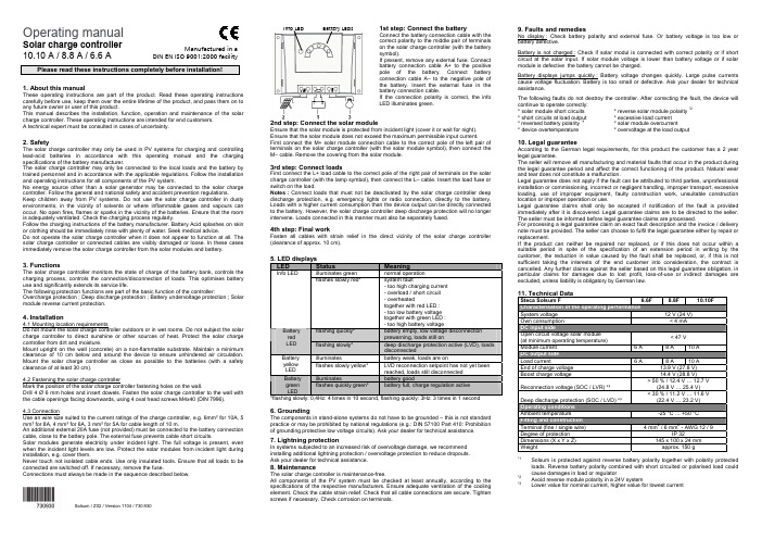
Operating manualSolar charge controller10.10 A / 8.8 A / 6.6 APlease read these instructions completely before installation!1. About this manualThese operating instructions are part of the product. Read these operating instructions carefully before use, keep them over the entire lifetime of the product, and pass them on to any future owner or user of this product.This manual describes the installation, function, operation and maintenance of the solar charge controller. These operating instructions are intended for end customers.A technical expert must be consulted in cases of uncertainty.2. SafetyThe solar charge controller may only be used in PV systems for charging and controlling lead-acid batteries in accordance with this operating manual and the charging specifications of the battery manufacturer.The solar charge controller may only be connected to the local loads and the battery by trained personnel and in accordance with the applicable regulations. Follow the installation and operating instructions for all components of the PV system.No energy source other than a solar generator may be connected to the solar charge controller. Follow the general and national safety and accident prevention regulations.Keep children away from PV systems. Do not use the solar charge controller in dusty environments, in the vicinity of solvents or where inflammable gases and vapours can occur. No open fires, flames or sparks in the vicinity of the batteries. Ensure that the room is adequately ventilated. Check the charging process regularly.Follow the charging instructions of the battery manufacturer. Battery Acid splashes on skin or clothing should be immediately rinse with plenty of water. Seek medical advice.Do not operate the solar charge controller when it does not appear to function at all. The solar charge controller or connected cables are visibly damaged or loose. In these cases immediately remove the solar charge controller from the solar modules and battery.3. FunctionsThe solar charge controller monitors the state of charge of the battery bank, controls the charging process, controls the connection/disconnection of loads. This optimises battery use and significantly extends its service life.The following protection functions are part of the basic function of the controller: Overcharge protection ; Deep discharge protection ; Battery undervoltage protection ; Solar module reverse current protection.4. Installation4.1 Mounting location requirementsDo not mount the solar charge controller outdoors or in wet rooms. Do not subject the solar charge controller to direct sunshine or other sources of heat. Protect the solar charge controller from dirt and moisture.Mount upright on the wall (concrete) on a non-flammable substrate. Maintain a minimum clearance of 10 cm below and around the device to ensure unhindered air circulation. Mount the solar charge controller as close as possible to the batteries (with a safety clearance of at least 30 cm).4.2 Fastening the solar charge controllerMark the position of the solar charge controller fastening holes on the wall.Drill 4 Ø 6 mm holes and insert dowels. Fasten the solar charge controller to the wall with the cable openings facing downwards, using 4 oval head screws M4x40 (DIN 7996).4.3 ConnectionUse an wire size suited to the current ratings of the charge controller, e.g. 6mm² for 10A, 5 mm² for 8A, 4 mm² for 6A, 3 mm² for 5A for cable length of 10 m.An additional external 20A fuse (not provided) must be connected to the battery connection cable, close to the battery pole. The external fuse prevents cable short circuits.Solar modules generate electricity under incident light. The full voltage is present, even when the incident light levels are low. Protect the solar modules from incident light during installation, e.g. cover them.Never touch not isolated cable ends. Use only insulated tools. Ensure that all loads to be connected are switched off. If necessary, remove the fuse.Connections must always be made in the sequence described below.1st step: Connect the batteryConnect the battery connection cable with thecorrect polarity to the middle pair of terminalson the solar charge controller (with the batterysymbol).If present, remove any external fuse. Connectbattery connection cable A+ to the positivepole of the battery. Connect batteryconnection cable A– to the negative pole ofthe battery. Insert the external fuse in thebattery connection cable.If the connection polarity is correct, the infoLED illuminates green.2nd step: Connect the solar moduleEnsure that the solar module is protected from incident light (cover it or wait for night).Ensure that the solar module does not exceed the maximum permissible input current.First connect the M+ solar module connection cable to the correct pole of the left pair ofterminals on the solar charge controller (with the solar module symbol), then connect theM– cable. Remove the covering from the solar module.3rd step: Connect loadsFirst connect the L+ load cable to the correct pole of the right pair of terminals on the solarcharge controller (with the lamp symbol), then connect the L– cable. Insert the load fuse orswitch on the load.Notes : Connect loads that must not be deactivated by the solar charge controller deepdischarge protection, e.g. emergency lights or radio connection, directly to the battery.Loads with a higher current consumption than the device output can be directly connectedto the battery. However, the solar charge controller deep discharge protection will no longerintervene. Loads connected in this manner must also be separately fused.4th step: Final workFasten all cables with strain relief in the direct vicinity of the solar charge controller(clearance of approx. 10 cm).5. LED displaysLED Status Meaningilluminates green normal operationInfo LEDflashes slowly red* system fault- too high charging current- overload / short circuit- overheatedtogether with red LED :- too low battery voltagetogether with green LED :- too high battery voltageflashing quickly* battery empty, low voltage disconnectionprewarning, loads still onBatteryredLED flashing slowly* deep discharge protection active (LVD), loadsdisconnectedilluminates battery weak, loads are onBatteryyellowLEDflashes slowly yellow* LVD reconnection setpoint has not yet beenreached, loads still disconnectedilluminates battery goodBatterygreenLEDflashes quickly green* battery full, charge regulation active*flashing slowly: 0,4Hz: 4 times in 10 second, flashing quickly: 3Hz: 3 times in 1 second6. GroundingThe components in stand-alone systems do not have to be grounded – this is not standardpractice or may be prohibited by national regulations (e.g.: DIN 57100 Part 410: Prohibitionof grounding protective low voltage circuits). Ask your dealer for technical assistance.7. Lightning protectionIn systems subjected to an increased risk of overvoltage damage, we recommendinstalling additional lightning protection / overvoltage protection to reduce dropouts.Ask your dealer for technical assistance.8. MaintenanceThe solar charge controller is maintenance-free.All components of the PV system must be checked at least annually, according to thespecifications of the respective manufacturers. Ensure adequate ventilation of the coolingelement. Check the cable strain relief. Check that all cable connections are secure. Tightenscrews if necessary. Check corrosion on terminals.9. Faults and remediesNo display : Check battery polarity and external fuse. Or battery voltage is too low orbattery defective.Battery is not charged : Check if solar modul is connected with correct polarity or if shortcircuit at the solar input. If solar module voltage is lower than battery voltage or if solarmodule is defective the battery cannot be charged.Battery displays jumps quickly : Battery voltage changes quickly. Large pulse currentscause voltage fluctuation. Battery is too small or defective. Ask your dealer for technicalassistance.The following faults do not destroy the controller. After correcting the fault, the device willcontinue to operate correctly:* solar module short circuits * reverse solar module polarity *2* short circuits at load output * excessive load current* reversed battery polarity *1* solar module overcurrent* device overtemperature * overvoltage at the load output10. Legal guaranteeAccording to the German legal requirements, for this product the customer has a 2 yearlegal guarantee.The seller will remove all manufacturing and material faults that occur in the product duringthe legal guarantee period and affect the correct functioning of the product. Natural wearand tear does not constitute a malfunction.Legal guarantee does not apply if the fault can be attributed to third parties, unprofessionalinstallation or commissioning, incorrect or negligent handling, improper transport, excessiveloading, use of improper equipment, faulty construction work, unsuitable constructionlocation or improper operation or use.Legal guarantee claims shall only be accepted if notification of the fault is providedimmediately after it is discovered. Legal guarantee claims are to be directed to the seller.The seller must be informed before legal guarantee claims are processed.For processing a legal guarantee claim an exact fault description and the invoice / deliverynote must be provided. The seller can choose to fulfil the legal guarantee either by repair orreplacement.If the product can neither be repaired nor replaced, or if this does not occur within asuitable period in spite of the specification of an extension period in writing by thecustomer, the reduction in value caused by the fault shall be replaced, or, if this is notsufficient taking the interests of the end customer into consideration, the contract iscancelled. Any further claims against the seller based on this legal guarantee obligation, inparticular claims for damages due to lost profit, loss-of-use or indirect damages areexcluded, unless liability is obligatory by German law.11. Technical DataSteca Solsum F 6.6F 8.8F 10.10FSystem voltage 12 V (24 V)Own consumption < 4 mADC input sideOpen circuit voltage solar module(at minimum operating temperature)< 47 VModule current 6 A 8 A 10 ADC output sideLoad current 6 A 8 A 10 AEnd of charge voltage 13.9 V (27.8 V)Boost charge voltage 14.4 V (28.8 V)Reconnection voltage (SOC / LVR) *³> 50 % / 12.4 V … 12.7 V(24.8 V … 25.4 V)Deep discharge protection (SOC / LVD) *³< 30 % / 11.2 V … 11.6 V(22.4 V … 23.2 V)Operating conditionsAmbient temperature -25 °C … +50 °CFitting and constructionTerminal (fine / single wire) 4 mm2 / 6 mm2 - AWG 12 / 9Degree of protection IP 32Dimensions (X x Y x Z) 145 x 100 x 24 mmWeight approx. 150 g*1Solsum is protected against reverse battery polarity together with polarity protectedloads. Reverse battery polarity combined with short circuited or polarised load couldcause damages in load or regulator*2Avoid reverse module polarity in a 24V system*3Lower value for nominal current, higher value for lowest currentInfo LED Battery LEDsManufactured in aDIN EN ISO 9001:2000 facilitySolsum / Z02 / Version 1104/ 730.930。
太阳能充放电控制器使用手册

13
Phocos CA
Solar Charge Controller User Manual (English)
Dear customer, Thank you very much for buying this Phocos product. Please read the instructions carefully and thoroughly before using the product.
14
Your new CA controller is a state-of-the art device which was developed in accordance with the latest available technical standards. It comes with a number of outstanding features, such as: 3 LEDs for a clear, readable display of the state of charge 16 mm2 connector clamps Temperature compensation Electronic protection without fuses Please read this manual carefully taking special note of the safety and usage recommendations at the end. The manual gives important recommendations for installing, using and programming as well as a troubleshooting guide for potential problems with the controller.
控制器英文说明书(英文面板)
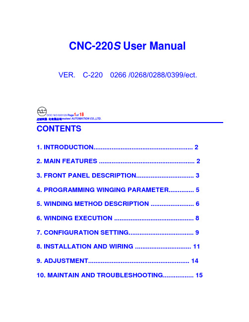
CNC-220S User Manual VER. C-220 0266 /0268/0288/0399/ect.DOC NO:020129 Page1of 18迈维自動化有限公司maiwei AUTOMATION CO.,LTD.CONTENTS1. INTRODUCTION (2)2. MAIN FEATURES (2)3. FRONT PANEL DESCRIPTION (3)4. PROGRAMMING WINGING PARAMETER (5)5. WINDING METHOD DESCRIPTION (6)6. WINDING EXECUTION (8)7. CONFIGURATION SETTING (9)8. INSTALLATION AND WIRING (11)9. ADJUSTMENT (14)10. MAINTAIN AND TROUBLESHOOTING (15)迈维自動化有限公司maiwei AUTOMATION CO.,LTD.1. INTRODUCTIONCNC-220S is a series of COIL WINDING MACHINE CONTROLLERdeveloped by MAIWEI AUTOMATION . It not only retains all the features ofprevious designs, it also has a low noise level and is less sensitive to externalpower fluctuation.CNC-220S also features an integrated design: putting stepper motor driver,DC motor speed controller, brake and power supplier control circuits into onecontrol box, simultaneously achieving size reduction, high performance andlow cost.CNC-220S Series offers CNC-220S “Standard Model” and CNC -220S EXD"External Connection Model”, depending on whether a close -loop driver isprovided for various applications.2. MAIN FEATURES◆ Single chip DSP Microprocessor design, has further higher performance and higher functions; it also has less sensitive to external power fluctuation orto external electromagnetic interference.◆ Memory capacity capable storing up to 0- 1000 steps winding data, 9 winding parameters, and 5 options can be independentlyassigned for each step. Off-power memory retention without battery.◆ Winding speed can be specified using the front panel keypad, resulting ineasy programming of multi-step, multi-speed settings.◆ Guiding traverse shaft stepper motor with a constant-current driver offeringfast wire guiding speeds.◆ Power input AC100V~120V 、220V~240V 600VA(max).迈维自動化有限公司maiwei AUTOMATION CO.,LTD.3. FRONT PANEL DESCRIPTION3.1. Power switchPower:Power supplier equipped, controls the AC power to the controller.3.2. Key pads0-9:10 key, for entering numerical values.『QTY SET』:Enter into EDIT mode.『EDIT』:Specify target production quantity.『START STEP』:Specify starting step in memory.『END STEP』:Specify ending step in memory.『DATA SEL』:Select parameter to be programmed, or to switch display mode. 『FEED DIR』:Select guiding direction for each step.『WIND DIR』:Select winding direction for each step.『EDGE STOP』:To specify whether to suspend winding when the guiding traverse moves to the two edges of the width.『AUTO HOME』:Select whether to have auto-positioning function for each step. 『AUTO START』:Select whether to have auto-starting function for each step. 『-』:Reduce step number by one, or reduce PIECE COUNTER by one.『CLR』:During programming, clear current data to zero.『COPY』:Copy the data of previous step into current step.『ENT』:Write data into memory.『RPM』:Switch display to shows PIECE COUNT or RPM.『ZERO』:Hold down this key for two seconds to reset PIECE COUNTER to zero. 『AUTO』:To switch between AUTO and NON-AUTO mode.『BRAKE』:Switch whether brake will be applied to the win spindle during stopping.迈维自動化有限公司maiwei AUTOMATION CO.,LTD.『NEXT』:Skip current step and go to the next step.『PREV IOUS』:Discard current step and go to the previous step『RESET』:At any time, discontinues current operation and return to ready mode. 『STOP』:Pause during winding.『START』:Restart during pause, or pause during winding.←:guiding traverse moves to the left.→:guiding traverse moves to the right.:Show the current step number being wound or beingprogrammed.:During programming, in combination with LED, shows the parameter being programmed. During winding or ready mode, show thecurrent number of turns or show the guiding traverse shafts position.Shows PIECE COUNT or RPM.3.4. Status indicators□READY: lit means in READY mode, flash means PAUSE mode ,not litmeans winding or programming in progress.□RUN: lit means winding in progress; not lit means not in progress.□SLOW: during winding, lit means low speed winding; not lit means high speed winding.□MOVE: lit means guiding traverse is fixing the starting position forwinding or is returning to the home position.□O.S: lit means winding operation is over speeding, guiding traverseand winding spindle shaft are out of synchronization.□LAN: lit means currently communicating with network.□FINISH: will lit when reaching the preset piece count.□ RPM: lit means the PIECE COUNT DISPLAY shows RPM.□ QTY: lit means the PIECE COUNT DISPLAY shows the piece count.3.5. Winding parameters definitions□SHIFT : Starting position of the guiding traverse.[Setting range 0.00~ 999.99 mm].□WIDTH : The traverse of the copper wire led by the traverse duringwinding. [Setting range 0 ~999.99 mm].□PITCH : Diameter of the copper wire. [Setting range 0~ 9.999mm].□TURNS: Total number of turns to be wound.[Setting range 0.0~9999.9 or 0~99999 turns].□S.SLOW : Number of turns to be wound at low speed, when start winding.[Setting range 0~999.9 turns].□E.SLOW : Number of turns to be done at low speed prior to stopping.[Setting range 0 ~999.9 turns].□H.S.: High winding speed. [Setting range from 0~99%].□L.S. : Low winding speed. [Setting range from 0~25%].□FUN : Winding complete output signal setting.4. PROGRAMMING WINGING PARAMETER4.1. MEMORY RANGE SELECTIONCNC-220S contains 1000 memory step, By defining the region, users caneffectively manage the memory. Various winding parameter can be stored indifferent regions and can be retrieved instantaneously. After specifying theregions, programming and winding can be done in those regions; allun-selected regions will retain their original contents and unmodified. Whensetting the STEP number, the Ending step number must be larger than theStarting step number, or the winding operation will not startSpecifying starting stepIn ready mode, press to select. [Setting range 0 ~ 999].Specifying ending stepIn ready mode, press to select. [Setting range 0 ~ 999].4.2. Programming winding parameterIn “READY” mode, press invokes the programming mode. First the“START STEP” number will shows at “Procedures displayer”, the parameter indicator 『SHIFT』will lit, the starting position will shows at “Documents dispayer”. The starting position can be changed to the new position by pressing thenumerical keys followed by the key.After that the STEP number will automatically increase by one, to continue setthe starting position for next step. When the STEP number larger then the“END STEP”number, the STEP number will restore to the “START STEP”number and the indicator light will change from『SHIFT』to 『WIDTH』foruser to specifying the width for each STEP. Repeat the same procedure using numerical keys and the key, all winding parameters for each STEP canThe following functions are also available::To select guiding direction, forward or reverse.:To select winding direction, clockwise or counter-clockwise.:To specify whether to suspend winding when the guiding traversemoves to the two edges of the width.:To select whether guiding traverse returns to the starting positionautomatically or upon a manual pressing of the key.:Select whether to have auto-starting function for each step.:Clear the current value to zero.copy:Copy the content of the previous step to the current step.—:Go back to the previous programming step.:To scroll through different parameters.Each time when change the PARAMETER or OPTIONS, key mustpressed to effect the change.4.3. Guiding traverse shaft introduce settingDuring set the 『SHIFT』, 『WIDTH』and 『guiding traverse travel limit』,can use numeric keypad to set location data or can also use ,←or→keysTo leading the guiding traverse shaft location.4.4. Clear all winding parameterIn the”READY”mode, press will clear all the winding parameter inthe memory. Be cautious in using this function or all the data will be lost. 5. WINDING METHOD DESCRIPTIONPrior to winding, the general winding principles are explained below so the operators can have a better understanding of the performance of the controller and make better use of it.5.1. Counting mode(Refer to the section 7.1. Counting mode).◆Absolute counting modeWinding spindle shaft is capable of fixed-point stopping. Upon each restart,the turn count will reset only the integer portion of the turn’s to zero, with the decimal unchanged. For example, for a previous number of 100.3 turns, when restarting the next step winding, the counting will start with 0.3 turn to avoid accumulation of spindle shaft free play error from consecutive windings. This counting method may cause insufficient winding by one turn. Therefore, when starting from 0.5~0.9, the spindle will turn to the 0.0 before it starts counting.◆Relative counting modeThis counting method zeros the counter upon each restart, therefore it is easy to understand and will not cause insufficient winding.5.2. Wire-guiding mode◆Interlace wire-guidingIf the『幅宽』of the step is zero, the wire-guiding becomes interlace mode. When it begins winding, the wire-guiding will follow the wire direction to proceed two wire diameters and regress one wire diameters cyclically until the step of winding ends. This mode especially suits the inductor winding.◆Non wire-guidingSometimes, the winding device may be used to winding adhesive tapes or copper foil. When the wire-guiding is not needed, 『PITCH』may be adjusted to zero and the wire-guiding won't be move.5.3. Operation mode(Refer to the section 7.1. Operation mode).◆Single click modeWhen press the start switch, the motor start winding, and when you releasethe start switch, the motor stop winding immediately.◆Double click modeWhen press the start switch, the motor start winding, and if you want to pause the motor, you have to release the start switch then press it again.5.4. Running mode◆Continual modeBefore it begins winding, if『SHIFT』of the step set as 999.99, then the starting position, the width , the wire-guiding direction and the winding direction won't be re-read. The values are not changed, that is the wire guiding will continue guiding wires on the same position. The width and left-right margins are the same as the ones of the previous section. Both the wire-guiding and winding directions are not changed either. This mode especially suits to winding which have the multiple drawing tops in the same sets of coils.◆Edges slow modeThe winding speed will slow down before the guiding traverse reach to the two edges of the width (work with『E.SLOW』turns). After the guiding traverseCNC-220S USER MANUAL VER. Page 8 of 18迈维自動化有限公司maiwei AUTOMATION CO.,LTD.veered, then restore to hi-speed winding. (Refer to the section 7.1. edge slow mode).◆Automatically circularly modeIf key set to on, it means Automatically circularly mode, in this modewhen finish a step of winding it will automatically get into next step and start winding without press key (work with and keys).5.5. How to Correct setting turns◆Preset methodSet the 『E.SLOW』to zero first and then set the 『TURNS』to the desired number. Set proper parameters according to copper wire, bobbin, tension, etc, then press to start winding. When finished, obtain the actual number ofturns and calculate the number of overshot turns. Go into programming modeand subtract the number of the overshot turns from the 『TURNS』to obtainthe required setting.This method has a higher throughput, however, the resulting stopping location may not be precise.◆High-Low speed methodThis method uses a combination of 『H.S.』/『L.S』and 『E.SLOW』to achieve the desired number of turns.The『L.S.』should not be too high. The number of 『E.SLOW』turns must be adequate to allow the spindle shaft to slow down to low speed before reachingthe total number of turns. This can result in precise stopping location.◆Double-brake methodAs the winding turns of the winding shaft reach the numbers of the『E.SLOW』, brake for a short period first. After the winding shaft stops, continue winding atlow speed. Therefore the numbers of the slow speed may be reduced and the efficiency of winding may be increased, (Refer to the section 7.1. braking mode).6. WINDING EXECUTION6.1. To start windingAfter set up all data items, press key,the winding process begins in accordance with the set-up content. Press key to pause winding. During winding, press the key, the winding speed can be switch between highspeed and low speed.The following key functions are available during PAUSE mode::Give up the numbers of the winding turns and regress one step.:Finish current step and proceed to next step.CNC-220S USER MANUAL VER. Page 9 of 18迈维自動化有限公司maiwei AUTOMATION CO.,LTD.Continue winding.: Give u p winding and go back to the”READY ”mode.6.2. Change the display modeDuring winding or during PAUSE mode, press key, the“Documents displayer ” can be change the display mode between turns or guiding traverse position.6.3. Winding speed (RPM) displayPress ing key will cause the”QTY displayer ” to display the spindleshaft “RPM ” without interrupting the counting. Pressing again will change the“QTY displayer ” back to displaying the piece count.6.4. Piece counter managementUpon turning on the “POWER ”, “QTY displayer ” will showsthe number of piece produced. During wining, each time the CONTROLLERgoes from the “Stert step ” to the “End step ”, the piece counter willautomatically increase by one.◆ Preset piece counterIn “ready ” mode, press key once and key in desired values followedby the key. When the “QTY displayer ”reaches the preset value, theFINISH led will lit. [Setting range 0~99999].◆ Decrease piece counterDuring “READY ”or PAUSE mode, press the key and hold down for twoseconds the piece counter will decrease by one.◆ Reset piece counterIn any time holding down key for two seconds, it will set the piececounter to zero.7. CONFIGURATION SETTINGCNC-220s is a multi-purpose design, to meet various requirements;additional settings are configured to provide flexibility for additionalapplications.In the “READY ” mode, press the following keys combination as section[7.1.~7.8], the “Documents displayer ” will show corresponding setting value. If no change is necessary, press the key get back to “READY ” mode. Orpress key to get into change mode, then the parameter can be changed bypressing the numerical key followed by the key. 7.1. Winding mode selection 『EDIT 』 『DATA SEL 』In this function the STEP display and the DATA display will shows eight digits, representing eight winding mode selections respectively.Press numerical keys as below to set each digit.CNC-220S USER MANUAL VER. Page 10 of 18邁維自動化有限公司maiwei AUTOMATION CO.,LTD.7 6 5 4 3 2 1 :The guiding traverse moving speed.0 represents high speed ; 1 represents low speed.2 Moving increment :The travel increment of the guiding traverse.1 represent 0.01mm (4 mm per revolution).2 represent 0.02mm (8 mm per revolution).3 represent 0.01mm (5mm per revolution).4 represent 0.04mm(16 mm per revolution. 3Counting mode :Select the counting mode of the winding spindle shaft. 0 represents with zero point and using absolute counting mode.1 represents without zero point and using relative counting mode. 4Edge slow :Slow down the winding speed before the guiding traverse reach to the two edges of the width.0 represents not slow down ; 1 represents to slow down. 5Braking mode :Select the braking mode of the winding spindle. 0 represents single brake mode ; 1 represents double brake mode. 6Counting unit :Select 0.1 or 1 turns as your count unit. 0 represents 0.1(0.0 to 9999.9 turns); 1 represents 1(0 to 99999 turns). Guiding traverse unit :Select the basic unit of guiding traverse.0 represents mm; 1 represents inch (must using lead screw in imperial). Operation mode :Select operation mode for the START switch.0 represents Single click mode ; 1 represents Double click mode.The key on the front panel always as the Double click mode.7.2. Password 『EDIT 』 『DATA SEL 』 2This password is used to protect the setting data in memory. After you set this password, you cannot change any winding parameter and configuration data in normal sequence. You have to key in four numbers of password before press the ,『ENT 』『START STEP 』,『END STEP 』,『QTY SET 』 keys. If the password has been passed once, youcan change any data in normal sequence until you turn off the power or press key. You must to remember the password or you cannot change any data.[Setting range 0000~9999]. Set 0000 means no password.7.3. Travel limit 『EDIT 』 『DATA SEL 』 3Set the maximum travel distance of guiding traverse. During winding when the guiding traverse reaches this position, the motor stop winding immediately,and the “Documents displayer ” shows error massage, then “RESET ” and goback to the“READY ” mode. [Setting range 000.00~999.99]. 999.99 Means no limit. 7.4. Fixed location 『EDIT 』 『DATA SEL 』 4To set how often, must be correct the guiding traverse location. Each time when finish this number of product pieces, the guiding traverse will moves to the home position to correct the location before moving to starting position. [Setting range 00~ 99]. Set 00 means not to do this function.7.5. Limited winding speed 『EDIT 』 『DATA SEL 』 5 This value is to limited winding speed and make sure the winding spindle shaft and guiding traverse are in synchronization. The controller uses this value to calculate with wire PITCH of current step, and then to limited maximum winding speed of current step.[Setting range 0~ 99999]. Set 0 means no limit speed.7.6. Brake holding time 『EDIT 』 『DATA SEL 』 6 To set the hold times for brake. [Setting range 0.1~9.9 sec].7.7. Acceleration times 『EDIT 』 『DATA SEL 』00 means shortest acceleration times ;99 means longest acceleration times. 7.8. Deceleration times 『EDIT 』 『00 means shortest deceleration times ;99 means longest deceleration times.8. INSTALLATION AND WIRING◆The controllers should be operated in an environment that is protected from moisture, corrosive gases, or liquid, and free from airborne dust, metallic particles, and magnetic noise.◆Do not block the intake/exhaust ports of the controller. Otherwise, a fault may occur.◆Make sure that the power source supplies the correct voltage and is capable of supplying the required current to the controllers.◆Do not connect or disconnect wires and connectors while power is applied to the controller.Make sure the machine and controllers are properly grounded. Make sure that the leads and connectors are connected correctly.◆Normally operate under 10℃ ~ 40℃ environment ; over 40℃ should perform under good ventilation, avoid heating.8.2. Wiring diagram for CN3~CN6FOOT SWITCH Operate Switches Home Sensor Turn Counter AUX I/O邁維自動化有限公司maiwei AUTOMATION CO.,LTD.8.3. Wiring diagram for CNC-220SAC Input DC90-180V/90-400W DC24V 12W 2Phase 6V 2ADC MOTOR BRAKE STEP MOTOR Drive STEP Motor in directlyAC Input Motor Driver DC24V 12W 2Phase 6V 2ABRAKE STEP MOTOR External connect STEP Motor driver邁維自動化有限公司maiwei AUTOMATION CO.,LTD.AC Input Motor Driver DC24V 12W Step Motor DriverBRAKE9. ADJUSTMENT9.1. Adjustments for CNC-220SACC: Acceleration timesRotate ACC to set the accelerate times for the winding spindleCL:Output current limit.1. Connect a DC Amperes meter between terminal and DC motor as below.2. In ready mode press to make the DC motor starting rotate andthen press to holding the winding spindle.3. Rotate CL to set limited current, show on Amperes meter.( 2A for 180v DC motor、4A for 90v DC motor).(The CL have been set by factory before delivery. Only adjust it when change DC motor and replace 220-DVR driver board.)IR:Torque compensation.1. Set the winding parameter “H.S”、”L.S”. in 20, then press to change the DISPLAY shows RPM. Then press key to start winding.2. Rotate IR potentiometer to make it in same speed during the winding spindle shaft in full-load and unload. Then press key to stop winding.MAX:Maximum winding speed.3. Set the winding parameter“H.S”、”L.S”. in 99, and press key to change the DISPLAY shows RPM. Then press key to start winding.4. Rotate MAX potentiometer to make the winding speed (RPM) as you wantThen press key to stop winding.CNC-220S CNC-220S EXD9.2. Adjustments for CNC-220S EXDSpeed Mode selectionTo select the speed signal output mode for winding driver.Selected by JP1.1. Vout mode:Represents the speed signal with DC 0~10v output.2. H/L mode:Represents the speed signal with HI/LOW lever output.Hi speed with HI lever, low speed with LOW lever.Vout adjust1. Set the winding parameter “H.S”、”L.S”.in 99, and press“MAX” key to change the DISPLAY shows RPM. Then press key to start winding.2. Rotate Vout potentiometer to make the winding speed (RPM) as you want.Then press key to stop winding.3. This function only worked in Vout mode.110.MAITAIN AND TROUBLESHOOTING110.1. Periodically maintain◆Please periodically clean up the controller inner accumulate dust and dopants.◆Please periodically check the wire connection between controller and machine if have loose or bad contact.◆The following parts must be maintained or changed periodically as listbelow. If any part is found faulty, it must be changed immediately evenwhen it has not yet reached the end of its life, which depends on theoperating method and environmental condition.◆For parts replacement, please contact your sales representative.10.2. Error messageWhen a fault occurs during operation, the DATA DISPLAY shows errormassage, stop wi nding and then “RESET”go back to the “READY” mode.Err-0:The parameters or data in memory are fault.Err-1:The『SHIFT』value sets exceed the Travel Limit.Err-2:During winding, the guiding traverse to exceed the Travel Limit.Err-3:During winding, the guiding traverses reach to the Home sensor.10.3. To abort seeks the original positionAt boot and reset procedures, if because of unknown reason howeverengender the winding shaft and guiding traverse can't find out the originalposition and make the controller can't get into ready mode, can press keyto abort seeks the original position, make controller get into ready mode.10.4. TroubleshootingThis section provides information to guide the user in understanding differentfault condition and their general troubleshooting procedures, and with their possible solutions.◆Do not connect or disconnect wires and connectors while power is appliedto the controller.◆Make sure that the leads and connectors are connected correctly, beforedoing the troubleshooting procedures.◆Do not remove welded parts on the PC board without appropriate tools.CNC-220S USER MANUAL VER. Page 17 of 18邁維自動化有限公司maiwei AUTOMATION CO.,LTD.CNC-220S USER MANUAL VER. Page 18 o18邁維自動化有限公司maiwei AUTOMATION CO.,LTD.。
太阳能热水器控制器说明书

太阳能热水器控制器说明书关键信息项:1、产品名称:太阳能热水器控制器2、产品型号:________________________3、工作电压:________________________4、控制功能:________________________5、显示方式:________________________6、防护等级:________________________11 产品概述本太阳能热水器控制器是专门为太阳能热水器系统设计的智能化控制设备,能够实现对太阳能热水器的自动化控制和监测,提高热水器的使用效率和安全性。
111 主要特点1、精准的温度和水位检测,确保系统运行稳定可靠。
2、智能化的控制算法,根据天气和用水情况自动调整工作模式。
3、直观的显示界面,方便用户随时了解热水器的工作状态。
4、具备多种保护功能,如过热保护、漏电保护等,保障用户使用安全。
112 技术参数1、工作电压:具体电压值2、工作温度:温度范围3、水位检测精度:精度值4、温度检测精度:精度值12 安装与连接121 安装位置选择应选择干燥、通风良好、易于操作和观察的位置,避免阳光直射和雨淋。
122 连接线路按照控制器上的标识,正确连接电源线、传感器线、负载线等,确保连接牢固可靠。
13 操作说明131 开机与关机接通电源后,控制器自动开机,进入工作状态。
长按关机按钮可实现关机操作。
132 功能设置通过控制面板上的按键,可以设置水温、水位、加热时间等参数。
133 手动控制与自动控制切换可根据需要在手动控制和自动控制模式之间切换,手动控制时可单独操作加热、上水等功能。
14 显示界面141 水温显示实时显示热水器内的水温,单位为摄氏度。
142 水位显示以图形或数字的方式显示热水器内的水位高度。
143 工作状态指示显示加热、上水、保温等工作状态的指示灯。
15 故障报警与处理151 常见故障包括传感器故障、漏电故障、过热故障等。
152 报警方式通过声音、灯光等方式进行报警提示。
SR-L系列_太阳能智能型控制器使用说明书(英文版)

SR-L Series solar power intelligent PV controllerInstruction bookMain features1.Intelligent control is realized by using microprocessor and dedicated control calculation.2. Four load working modes: Pure lighting control, lighting control & timing control, hand operation and debug mode.3. Scientific management of battery: as it is overcharged, the battery will get booster tension charge. As a result compulsory maintenance is available for the battery. In normal working state, the direct charge and floating charge are both available, so that the battery life-span is increased. Besides, the adoption of high precision temperature compensation makes the charging more accurate.4. Comparing with the charging loops using diodes, the one that adopts double MOS series circuit control makes the voltage loss dropped by 50%. With the PWM fuzzy control in charging, the charge efficiency is improved a lot.5. LED screen shows the working state of solar battery, storage battery and load. LED shows the adjusted parameter. In this way, users can learn the operation state in ream time. Besides, there are various choices for parameter; users can select the proper working mode based on the different conditions.6. Various protections include over-charge, over-discharge and over-load, as well as unique electron short circuit protection and connection-reverse protection. All the protections are harmless to any parts and fuse. TVS thunder proof protection is also available. Non wire jumpers design improves the reliability and durability of the products.7. Technical grade chips and precision components are adopted for all the controls. Therefore, the controller performs well in very low and high temperature, as well as humid environment. At the same time, with the use of crystal timing control, the timing function of controller is much more reliable.8. Digital LED display and one button setup make the device easy to handle.9. Discharge rate revision controls: Different discharge rate matches with different cut-off voltage, which is in compliance with the characters of storage battery.System descriptionOur controllers are specially designed for solar power DC supply system, solar power DC street lamp system and mini solar power station system. Intelligent control is realized by using dedicated computer chips. The controllers can be used in hard environment, since its adoption of technical grade chips. To the controllers with 12V/24V automatic identification function, the system will identify the voltage when the controllers are charged initially. When LED shows “0”, it means the system voltage is 12V. While shows “1”, means 24V.The short circuit, over-load, connection-reverse protection, as well as over-charge, over-discharge protection are available. Besides, the complete indications are usable, including indications for states of charge, storage battery and faults.Through the computer chips, the controllers take samples from the parameters of storage battery voltage, photo battery, discharge current and environment temperature, and then use the dedicated control mode calculation to control the discharge rate and make it matched with the characters of storage battery, realize the high accurate temperature compensation. PWM fuzzy charge mode and 7 phase voltage control are available for the storage battery, so that storage battery is always in the perfect working state .The various working modes of controllers can meet customers’ different requirements.Installment and use1.The controller must be well fixed. The dimension of the controller is as following:Outside dimension: 140×90×25 (mm); installation dimension: 133.5×69.5 (mm) 2.Leads: the leads must be matched with the current. The length of stripped leads at theend of controller should be about 5mm. The longer the leads, the more the loss.3.The connection to storage battery: Pay attention to the “+” and “–” in case of reverseconnection. If it is connected well, the indication light will be on. Otherwise, please check the connection.4.The connection to solar panel: Pa y attention to the “+” and “–” in case of reverseconnection. If it is connected well, the indication light will be on. Otherwise, please check the connection.5. The connection to load: connect the leads with load of controller . The two interfaces are in parallel connection, and the total current must be less than rated current. Pay attention to the “+” and “–” in case of reverse connection which may damage of the device.outside view of the controllerParameter LED Nixie tubeOperation procedureA. Working state indication:①. Charged state indication : the solar indicator light is on, as the input voltage of solar battery panel reaches a certain point. The indicator light flashes slowly, as the storage battery is charging. The indicator light will flash quickly, as the system is over voltage.②. Storage battery indication: when the battery is under voltage, the indicator light flashes slowly. Over-charged for more than 10 seconds, the indicator light flashs quickly and the load is off. In normal working state, the indicator light is on continually.③. Load indication: when the load is in normal working state, indicator light is on continually. In over current, indicator light flashs slowly. In short circuit, the load is off at once and the indicator light flashs quickly. While the current is more than 1.25 times of rated current or more than 1.5 times for 5 seconds, the load of controller will be off.state Indicator light Off On Flash slowly Flash quickly Solar panel Low voltage (at night ) Fullvolta (daytime ) Charging Over voltage Storage battery - Norm Under voltage Over discharge load Load is off Norm Over current Short circuitstate of indicator lightB. Setting methods:To press the button for 3 seconds, the LED flashes and the system of the device is under mode of regulation. After releasing the key, the datain the LED changes along with every key-press till matches with the model designated by customers. To finish the setting, please wait until the LED stops to flash. Or just press the button for 3 seconds.C. Modes description①.Lighting control: without sunshine the light intensity decreases to start point. Then the controller recognizes the start signal after 10 minutes. Based on the parameter , the load is on. While under sunshine, the light intensity increase to start point, and then the controller recognizes the close signal after 3 minutes. The load is off.② Time control: The starting procedure is the same with that of pure lighting control. Timing control is dual period control; hence the double load can be regulated respectively. The load-on and load-off are alternated till the load is off in daytime. The time for the load-on and load-off can be adjusted to realize the different control effect. If the time for load-on is zero, the load will be off at night till the time for load-off is past. If the time for load-off is zero, the control effect will be the same with that of pure lighting control.③Manual mode: Regardless of the daytime or night, users can control the load-on and load-off by key-press under this mode. This mode is used for some special load or regulation. Charging for battery Indicator lightBattery Indicator ligntLoad Indicator ligntParameter LED Nixie tubebutton+ - + - + - Solar panel Battery Load④Test mode: this mode is designed for system regulation. It is almost the same with pure optical mode except that the cancelation of 10 minutes delay (Please refer to pure lighting control). The load is on with optical signal. In reverse, without optical signal, the load is off. This feature makes it easier to check the system installation.Working mode setting tableParameter DescriptionData in LEDModeData in LED Mode0 Dusk-to-Dawn, light is on all light 99 hours light is turn on after sundown 1 1 hours light is turn on after sundown 0. 10 hours light is turn on after sundown 2 2 hours light is turn on after sundown 1. 11 hours light is turn on after sundown 3 3 hours light is turn on after sundown 2. 12 hours light is turn on after sundown 4 4 hours light is turn on after sundown 3. 13hours light is turn on after sundown 5 5 hours light is turn on after sundown 4. 14 hours light is turn on after sundown 66 hours light is turn on after sundown 5.Manual mode7 7 hours light is turn on after sundown 6. Test mode, lights on after it detects no light, lights off after it detects light. 88 hours light is turn on after sundown7.Load open all timesModelSR-L seriesrated charging current □5A □10A □15A □20A Rated discharging current □5A □10A □15A □20AVoltage□12V ; □24V ; □12V/24V AutoNo load losses<5mA ; Charging circuit voltage dropLess than or equal to 0.20V Discharge circuit voltage dropLess than or equal to 0.15VOver voltage protection 17V ;×2/24V ;boost charge voltage 14.6V; ×2/24V (time of duration: 30 minutes) Direct charge voltage 14.4V ;×2/24V (time of duration: 30 minutes)Float charge voltage 13.6V ;×2/24V Charge recover voltage 13.2V ;×2/24VOver discharge recover voltage12.5V ;×2/24V Lower voltage indication12.0V ;×2/24VOver discharge voltage 11.1V ;×2/24VTemperature compensation -4.0mV/℃/2V(boost voltage, direct charge, float charge and charge returnvoltage compensation) Control methodPWM Smart Charging Working temperature From -35℃ to +65℃;Over-load and short circuit protectionOver-load protection: when the current of controller is 1.25 times of the rated current, the controller works for 30 seconds; 1.5 times of rated current, works for 5 seconds Short circuit protection: when the current of controller is more than or equal to 3 times of rated current, the protection starts. Circuit protectionOver-charge, over-discharge, shortcircuit and over-load protectionAll the protections are harmless to any parts and fuse of controller Anti- connection-reverse protection for solar battery and storage battery.FAQphenomenon solutionUnder the sunshine, the indicator light (NO.1) of solar panel is off Please check the line connected to photocell and make sure the proper connectionAs the cell panel is charged, the indicator light (NO.1) flashes quickly. The system is over-voltage. Please check whether the storage battery is well connected, or its voltage is too high.The indicator light (NO.2) of storagebattery is off Please check whether the storage battery is well connected. The indicator light (No.2) of storagebattery flashes quickly without output.The storage battery is over-discharged.The indicator light (No.3) of load flashes slowly without output. The load power is higher than the rated power. Please stop the operation of some equipment which consumes power, and then press the key for a longer time.The indicator light (No.3) of load flashes quickly without output. The load is short circuit and need to be adjusted. Then press the key for a longer time or wait till the next day, it will restart to work.The indicator light (No.3) is on continually without output. Please check whether the equipment which consumes power is well connected.Others Please check the connection, 12/24v Auto identified。
solar controller Manual说明书

■常见故障现象及处理方法:在出现下列现象时,请按照下述方法进行检查:■技术指标:光合太阳能控制器使用说明书■主要特点:1、使用了单片机和专用软件,实现了智能控制;2、利用蓄电池放电率特性修正的准确放电控制。
放电终了电压是由放电率曲线修正的控制点,消除了单纯的电压控制过放的不准确性,符合蓄电池固有的特性,即不同的放电率具有不同的终了电压。
3、具有过充、过放、电子短路、过载保护、独特的防反接保护等全自动控制;以上保护均不损坏任何部件,不烧保险;4、采用了串联式PWM充电主电路,使充电回路的电压损失较使用二极管的充电电路降低近一半,充电效率较非PWM高3%-6%,增加了用电时间;过放恢复的提升充电,正常的直充,浮充自动控制方式使系统有更长的使用寿命;同时具有高精度温度补偿;5、直观的LED发光管指示当前蓄电池状态,让用户了解使用状况;6、所有控制全部采用工业级芯片(仅对带I工业级控制器),能在寒冷、高温、潮湿环境运行自如。
同时使用了晶振定时控制,定时控制精确;7、取消了电位器调整控制设定点,而利用了Flash存储器记录各工作控制点,使设置数字化,消除了因电位器震动偏位、温漂等使控制点出现误差降低准确性、可靠性的因素;8、使用了数字LED显示及设置,一键式操作即可完成所有设置,使用极其方便直观,9、全密封防水型(-S)具有完全的防水防潮性能。
■控制器面板图:到浮充电压,并保持浮充电压。
如果没有发生过放,将不会有提升充电方式,以防蓄电池失水。
这些自动控制过程将使蓄电池达到最佳充电效果并保证或延长其使用寿命。
■系统说明:本控制器专为太阳能直流供电系统、太阳能直流路灯系统设计,并使用了专用电脑芯片的智能化控制器。
采用一键式轻触开关,完成所有操作及设置。
具有短路、过载、独特的防反接保护,充满、过放自动关断、恢复等全功能保护措施,详细的充电指示、蓄电池状态、负载及各种故障指示。
本控制器通过电脑芯片对蓄电池的端电压、放电电流、环境温度等涉及蓄电池容量的参数进行采样,通过专用控制模型计算,实现符合蓄电池特性的放电率、温度补偿修正的高效、高准确率控制,并采用了高效PWM蓄电池的充电模式,保证蓄电池工作在最佳的状态,大大延长蓄电池的使用寿命。
- 1、下载文档前请自行甄别文档内容的完整性,平台不提供额外的编辑、内容补充、找答案等附加服务。
- 2、"仅部分预览"的文档,不可在线预览部分如存在完整性等问题,可反馈申请退款(可完整预览的文档不适用该条件!)。
- 3、如文档侵犯您的权益,请联系客服反馈,我们会尽快为您处理(人工客服工作时间:9:00-18:30)。
ContentsContents----------------------------------------------------------------------------------1 1. Safety information --------------------------------------------------------------2 1.1 Installation and commissioning -----------------------------------------------2 1.2 About this manual ----------------------------------------------------------------2 1.3 Liability waiver ---------------------------------------------------------------------3 1.4 Important remark-------------------------------------------------------------------31.5 Description of symbols-----------------------------------------------------------32. Installation -------------------------------------------------------------------------4 2.1 Installing the controller ----------------------------------------------------------4 2.2 Power connection -----------------------------------------------------------------42.3 Terminal connection -------------------------------------------------------------63. Function setting------------------------------------------------------------------8 3.1 Illustration of controller panel--------------------------------------------------8 3.2 Setting the time--------------------------------------------------------------------8 3.3 Manual heating -------------------------------------------------------------------93.4 Timing heating--------------------------------------------------------------------104. Installation system diagram------------------------------------------------125. Protection function -----------------------------------------------------------13 5.1 Memory protection--------------------------------------------------------------13 5.2 Screen protection --------------------------------------------------------------135.3 Trouble protection---------------------------------------------------------------136. Quality guarantee -------------------------------------------------------------137. Technical data------------------------------------------------------------------148. Delivery scope-----------------------------------------------------------------149. Device matchable to this controller ------------------------------------151. Safety information1.1 Installation and commissioning•When laying cables, please ensure that no damage occurs to any of the constructional fire safety measures presented in the building. •The controller can not be installed in rooms where easily inflammable gas mixtures are present or may occur.•The permissible environmental conditions can not be exceeded at the site of installation.•Before connecting the device, make sure that the energy supply matches the specifications that controller requires.•All devices connected to the controller must conform to the technical specifications of the controller.•All operations on an open regulator are only to be conducted cleared from the power supply. All safety regulations for working on the power supply are valid. Connecting and /or all operations that require opening the regulator (e.g. changing the fuse) are only to be conducted by specialists.1.2 About this manualThis manual describes the installation, function and operation of a solar thermal controller. When installing the remaining components e.g. the solar collectors.and the storage unit, are sure to observe the appropriate installation instructions provided by each manufacturer. Installation, electrical connection, commissioning and maintenance of the device may only be performed by trained professional personnel. The professional personnel must be familiar with this manual and follow the instructions contained herein.1.3 Liability waiverThe manufacturer cannot monitor the compliance with these instructions or the circumstances and methods used for installation, operation, utilization and maintenance of this controller. Improper installation can cause damages to material and persons. This is the reason why we do not take over responsibility and liability for losses, damages or cost that might arise due to improper installation, operation or wrong utilization and maintenance or that occurs in some connection with the aforementioned. Moreover we do not take over liability for patent infringements or infringements – occurring in connection with the use of this controller- on third parties rights. The manufacturer preserves the right to put changes to product, technical date or installation and operation instructions without prior notice. As soon as it becomes evident that safe operation is no longer possible (e.g. visible damage). Please immediately take the device out of operation. Note: ensure that the device cannot be accidentally placed into operation.1.4 Important remarkWe have carefully checked the text and pictures of this manual and provided the best of our knowledge and ideas, however inevitable errors maybe exist. Please note that we can not guarantee that this manual is given in the integrity of image and text, they are just some examples, and they apply only to our own system. Incorrect, incomplete and erroneous information and the resulting damage we do not take responsibility.1.5 Description of symbolsSafety instruction:The safety instructions in the manual are marked with a warningtriangle. It indicates measures, which can lead to personal injury and safety risks.Operation steps: small triangle “►”is used to indicate operation step. Notes: Contains important information about operation or function. 2.InstallationController can only be installed indoors, and is far away from dangerous place and away from the electromagnetic field. Controller should be equipped with an additional plug, which should have minimum 3mm distance between the pole of the plug or effective compliance with the provisions of the installation. For example, switch or fuse, please note wires should be separated, and use the AC.2.1 Installing the controllerNote: the controller can only be installed in an area having an adequate level of protection.►Choosing a suitable site►Drilling the up fixing hole►Screwing on the screw►Taking away the cover plate►Hanging the bottom plate on the fixing hole ①②③►Marking the position of fixing hole &►Taking away the bottom plate②③►Drilling the hole &►Rehanging the bottom plate on screw ①►Fixing bottom plate with & screw②③2.2 Power connectionPower can only be switched on only when the housing of controller is closed; an installer must make sure that the IP protection class of the controller is not damaged during installation.Depending on the type of installation, the cables may enter the devicethrough the rear hole of the case or the lower side hole of the case④⑥④Cable come from the rear : remove the plastic flaps from the rear side of the case using an appropriate tool.Cable come from the below ⑥: Cut the left and right plastic flaps using an appropriate tool (e.g. knife) and break them out of the case.Notes: the flexible wire must be fastened to the case using thestrain-relief clamps provided2.3 Terminal connectionBefore to open the terminal, please be sure to switch-off thepower supplier and pay attention to the local electricity supplyrules.•Terminal layoutFU1 is the fuse of controller, AC250V/0.5A“Reset”button: This button is on the terminal connection panel, when system program is out of working, press “Reset” to recover the program of system to the factory settings.•Power connectionPower connection terminals are 10A current, please sure to connect to ground.•Output portsElectrical heater output H1: Electromagnetic relay, max. Switching current 20A, for electrical heater•input portsInput port T1:for NTC10K, B=3950 sensor, for measuring the temperature of tank.•Advice regarding the installation of temperature sensorOnly original factory equipped NTC10K,B=3950 temperature sensor are approved for use with tank, it is equipped with 20m PVC cable, and they are temperature resistant up to 105oC, not necessary to distinguish the positive and negative polarity of the sensor connection.All sensor cables carry low voltage, and it is necessary to take measures to avoid inductive effects, so sensor cables should not be laid close to 230 volt or 400 volt cables (minimum separation of 100mm)If external inductive effects are existed, e.g. from heavy current cables, overhead train cables, transformer substations, radio and television devices, amateur radio stations, microwave devices etc, then the cables to the sensors must be adequately shielded.Sensor cables may be extended to a maximum length of ca. 100 meter,when cable ’s length is up to 50m, and then 0.75mm 2 cable should be used. When cable ’s length is up to 100m, and then 1.5mm 2 cables should be used.3. Function settingConnect the sensor, electrical heater to the controller beforeyou connect the power supply!After switching on power to the controller, firstly it will ask for to set the time and set the parameter of system.3.1 Illustration of controller panel3.2 Setting time►Press “Clock” button, time displays on the screen, hour selection area “00” blinks on the screen.►Press “▲▼” button to set hour ofclock►Repress “Clock”, minute selectionarea“00”blinks► Press “▲▼” button to set minute of clock.► After setting, press “Clock” to exit program, or waiting for 12 seconds, controller exits automatically, the setup parameters are saved automatically.3.3 Manual heatingDescription:Electrical heater can be integrated into solar system as back-up, and it can be controlled by temperature, when controller checks the tank temperature T1 is 3o C below the preset temperature, electrical heater will be triggered. When tank temperature T1 reaches to the preset temperature, electrical heater is ceased.Condition for triggering heating: tank temperature is 3 o C below the the preset temperatureActivate/deactivate this function:► Press “manual” button, temperaturearea “60o C” blinks on the screen.► Press “▲▼” button to adjust theswitch-on temperature, adjustablerange: 30o C ~ 80o C, factory default: 60o C.After 12 seconds, this heating function is activated, heating signal displays on the screen.►Press “manual” button to switch-off manual heating function.Note: manual heating can only heat tank one time, after manual heating is triggered, when temperature of tank reaches to the setting temperature, manual heating ceases, and manual heating function will be deactivated automatically, if customer wants to heat again, you need redo according to above steps.3.4 Timing heatingFunction description:Electrical heater can be integrated into solar system used as back-up of system, and they can be triggered automatically at preset time by preset temperature. Within a preset time sections, when the temperature (T1) of tank drops below the preset switching-on temperature of this function, back-up heating starts to work, when T1 rises up to the preset turning off temperature, back-up heating is stopped. Within 24 hours, three time sections can be set with this controller.The adjustable range of switch-on temperature of heating is 30o C ~ (OFF-3o C), the adjustable range of switch-off temperature (On+3o C) ~ 80o C.Setup steps:►Press “SET” button for 3 seconds, to access the setting program, set the switch-on time of the first time section and its switch-on temperature, hour area blinks on the screen.►Press “▲▼” button, to set hour of the swith-on time of heating►Press “”button to transfer to minute area, minute blinks on thescreen►Press “▲▼” button, to set minuteof the swith-on time of heating►Press “” button to transferto temperature area, temperatureblinks on the screen,►Press “▲▼” button, to set the swith-on temperature of heating►Repress “SET” button, to access the setting program, set the switch-off time of the first time section and its switch-off temperature, hour areablinks on the screen.►Press “▲▼” button, to set hour of the swith-off time of heating►Press “”button to transfer to minute area, minute area blinks on the screen►Press “▲▼” button, to set minuteof the swith-off time of heating►Press “” button to transfer totemperature area, temperatureblinks on the screen,►Press “▲▼” button, to set the swith-off temperature of heating►Press “SET” button again, to access the setting program, set the switch-on time of the second time section and its switch-on temperature. Doling like above description, to set the second / third time section and its corresponding switch-on/ switch-off temperature.If you want to shut off one timing heating, then you can set the turning on time and turning off time same value ( for example, the second time section no this function, then you can set turning on/off time is 10:00 ~ 10:00)① Heating signal displays on the screen, it indicates timing heating is activated.Note:When time is outside of the preset time section, back-up heating doesn’t work automatically even when the tank temperature reaches the switch–on temperature of heating.The time in this controlled is 24 hours, when you set time section, the switch-off time of heating should be later than switch-on time. Forexample: if you set the switch-on time of heating is at 17:00, but switch-off time of heating is 6:00, then this setting doesn’t take effect, that means within this time section, heating function doesn’t work. The correct set is like flowing: it should be divided into two time sections, one time section is from 17:00 to 23:59, the other time section is from 00:00 to 06:00.When user selects electrical heater as back-up device, we recommend using SR801 unit connecting controller and electrical heater. (Detailed see )4. Installation system diagram5. Protection function5.1. Memory protectionIn case power failure occurs, controller keeps the parameter settings unchanged.5.2 Screen protectionWhen no any press on button for 3 minutes, screen protection is activated automatically, and then LCD lighting lamp is switched-off. Through press any button to light LCD lamp again.5.3 Trouble protectionWhen temperature sensor’s (T1) wiring is interrupted, not connected or short circuit, controller switchs off the corresponding signal output, and simultaneousely “ E1” error code displays on the screen.6. Quality GuaranteeManufacturer provides following quality responsibilities to end users: within the period of quality responsibilities, manufacturer will exclude the failure caused by production and material selection. A correct installation will not lead to failure. When a user takes incorrect handling way, incorrect installation, improper or crud handling, wrong connection of sensor in system and incorrect operation, the quality responsibility is invalid for them.The warrantee expires within 24 months after the date of purchasing the controller.7. Technical data•Appearance of controller: see product itself ( dimension: 179mm x120mm x43mm)•Power supply:AC230V ±10%•Power consumption:< 3W•Accuracy of temperature measuring:± 2o C•Range of tank temperature measuring:0 ~100 o C•Suitable power of electrical heater, ≤ 2000W•Inputs:1 piece NTC10K, B3950 sensor (≤ 135o C) for tank, (PVC cable ≤105o C),•Outputs:1 relay, for electrical heating•Ambient temperature :-10o C ~ 50o C.•Water proof grade:IP40.8. Delivery scope•Controller 1 piece •Power cable 1 piece •Customer manual 1 piece •NTC10K sensor(size: φ6*50mm,cable length20 m) 1 pieces •Plastic expansion screw 3 pieces •Screw 3 pieces •Strain-relief clamp 4 pieces9. Device matchable to this controllerl Contactor unit of high power: SR802When user selects electrical heater as back-up device, we recommend using SR802 unit connecting controller and electrical heater.Technical data of SR802Dimension: 100mmx100mmx65mmPower supply:180V~264V/AC 50/60HzSuitable power: ≤ 4000WAvailable ambient temperature: -10 ~ 50o CWater proof grade: IP43SR802 CONNECTION DIAGRAM:。