时序控制器英文说明书
Fadal控制器用户手册说明书
Section 6: Fixed SubroutinesDefinition Fixed Subroutines are dedicated cycles, standard in the memory of the control.They are called by the use of an L word (L9101 - L9901) and will useparameters (R0-R4, Z, & F). Fixed subroutines can be used during programsrun from memory or DNC operations. Subroutine calls are not allowed in MDI.L9101 ProbeFunctionsSee the Probe section for L9101 applications.EngravingL9201 EngravingFunctions Engraving functions are invoked by using the L9201 code. The L9201 function is capable of engraving either a constant text/number string or a serialized text/ number string. All lettering is uppercase.Parameters1) A tool must have been specified by an H or D word.2)The Z word defines the final depth of cut for the cycle. The maximum Zdepth from R0 plane to final is 2.5 inches.3)The R0word is used to define the clearance plane for the tool to moveabove the part. The tool retracts to this plane when moving betweencharacters, changing position to continue the same character, or after thelast character is engraved.4)R1 defines mode selection of four options:a. A value of 0 for standard Gothic font (R1+0.).b. A value of 1 for stencil type Gothic font (R1+1.).c. A value of 2 for serialization standard font (R1+2.).d. A value of 3 for serialization stencil font (R1+3.).5)R2 represents the height of characters to be engraved minus the tooldiameter. The maximum character height is 2.5 inches.6)R3 represents the angle at which the characters are to be engraved.(seefigure7)R4 is the serialization increment selector (1-9). Enter the R4 value for theincrement amount. R4+1. increments the number by one for each part. R1must be R1+2 or R1+3 to allow R4 to function.8)F is the feed rate.9)The comment or words typed after the ( (left parenthesis) will be engraved. Restrictions1)The maximum number of characters (including spaces) that can be engraved in each use of the L9201 code is 63 minus the number ofcharacters used to code the first part of the L9201 line itself.2)When serializing, the last part of the text/number string must be thenumber to increment.Engraving a Constant String The procedure to engrave the word “ENGRAVE” .125 inch high, using a .015 inch diameter engraving tool, is shown below:1)Position the X and Y to the start position (see Computing Start Position onpage 6-6).Note: This is true for engraving at an angle of zero degrees (see figure above).When engraving on a non-zero angle the X and Y axis must be shifted properly for the angle programmed.2)Position the Z axis to the Initial Plane.3)Set up the engraving cycle.EXAMPLE:N1 O1 (SAMPLE ENGRAVING PROGRAMN2 M6 T1N3 (TOOL #1 ENGRAVING TOOL .015 CENTER DRILLN4 G0 G90 S10000 M3 E1 X.375 Y-.6175N5 H1 D1 M8 Z.05 (DIAMETER .015 IN OFFSET PAGEN6 L9201 R0+.05 R1+0 R2+.125 R3+0 Z-.005 F40. (ENGRAVEN7 M5 M9N8 G90 G0 H0 Z0N9 E0 X0 Y0N10 M2Engraving a Serialized String Serialization is used to engrave numbers on a series of parts while changing the number on each part. The R1 value must be either a 2 or 3 to identify the serialized engraving style. The R4 value must be used to identify the increment amount. This amount is in whole numbers only (to increment decimal numbers, the decimal point must be engraved as a separate character). The numbers to be serialized MUST be at the end of the engraving characters. When serialization is coded, the machine changes the program code to reflect the next number to be engraved. The program code is changed after the control processes the engraving line. To reset the number, the operator must manually change the program code.Note: When the same number is to be engraved on each part, DO NOT use serialized engraving.EXAMPLE:N1 O1 (SAMPLE ENGRAVING PROGRAMN2 M6 T1N3 (TOOL #1 ENGRAVING TOOLN4 G0 G90 S10000 M3 E1 X.375 Y-.6175N5 H1 D1 M8 Z.05N6 L9201 R0+.05 R1+2. R2+.125 R3+0 R4+1. Z-.005 F40. (ENGRAVE 1N7 M5 M9N8 G90 G0 H0 Z0N9 E0 X0 Y0N10 M2Serialization Range Serialized engraving uses the number of digits at the end of the initial engraving string to set the range of serialization. For instance, if the end of thestring is 5 digits (00001), the maximum number engraved will be 99999, andthe number engraved after 99999 will be 00000.The preceding example engraves ENGRAVE 1 on the first part and ENGRAVE 2on the second and so on. This example will engrave the numbers 1, 2, 3, 4, 5,6, 7, 8, 9, and 0. After the 0 the number 1 is engraved again. Further, themaximum number of digits that could be coded in this example is five (00000through 99999), because 58 characters on the L9201 line are used byprogram code, including the spaces, right parenthesis, and constant portion ofthe engraving text.EXAMPLE:ENGRAVE 01 serializes the numbers 01 through 99, then 00, and then restarts at 01.ENGRAVE 0001 serializes the numbers 0001 through 9999, then 0000, andthen restarts at 0001.Spacing, Positioning,& Tool PathCalculations The L9201 Fixed Subroutine uses the Letter Box (the rectangular area around each character) to calculate the tool path for the engraving, beginning at the X, Y position specified in the program.Computing Actual Letter Height from the R2 Variable The L9201 Fixed Subroutine calculates the actual height of the tool path as follows:Actual height = (desired letter height) - (tool diameter)Computing StartSpacing The L9201 Fixed Subroutine calculates the start spacing for each character as follows:Start spacing = (actual height) * (start factor)Computing EndSpacing The L9201 Fixed Subroutine calculates the end spacing for each character as follows:End spacing = (actual height) * (end factor)Computing StartPosition X: The L9201 Fixed Subroutine will move to the X position specified in the program, and then move in X the amount calculated for the start spacing of the first character, before beginning the engraving cut.Y: The program must specify a starting Y position that takes into account the tool diameter, so that the tool is initially positioned one-half the tool diameter above the desired baseline of the engraving.X and Y should be specified together before each L9201 line.Computing Engraving Length Occasionally, it is necessary to calculate the length of the engraving. The procedure for calculating the length is as follows:1)Establish a desired height for the engraving.2)Choose the tool diameter. A recommended value is a diameter equal to .14times the desired height. Remember to place this diameter in the offset page.3)Calculate the width factor for the engraving, using the Letter Width Table tosum the width for each character or space.4)Calculate the total engraving length using the formula:Engraving length = (actual height) * (total width factor)EXAMPLE:Calculate the length of the word “ENGRAVE” to be engraved at a height of .125 inches with a tool diameter of .015 inches.1)Tool diameter = .015 inches2)Actual height = (desired letter height) - (tool diameter) = .125 - .015 inches= .110 inches3)Total width factor = the sum of the Letter Width Table’s width factors foreach character or space.E(.8853)+N(.9573)+G(.9588)+R(.9749)+A(1.0506)+V(1.0147)+E(.8853)=6.72694)The actual engraving length is now given by:Engraving length = (actual height) * (width factor)or, in this example, engraving length = (.110) * (6.7269) = .73996 Note: The tool diameter must be entered in the offset page, and an H word and/or D word must be used in the program prior to calling the L9201.Letter Width FactorValues The letter width is based on the box space for each letter. The Start and End factors are used to calculate the distance from the edge of the letter box to the start and end points of the letter.Table 1: Letter Width Factor TableCharacter Width Start EndA 1.0506 .2279.2279B.9455 .2279.1284C.9471 .1837.2677D.9441 .2279.1927E.8853 .2279.2280F.9118 .2279.2294G.9588 .2153.2282H.9706 .2279.2353I.4559 .2279.2280J.95 .2279.2280K 1.0249 .2279.2278L.8941 .2279.2280M 1.0824 .2279.2280N.9573 .2279.2279O.9647 .1779.1779P.9485 .2279.2279Q.9647 .1779.1779R.9749 .2279.2278S.9853 .2279.2280T.9485 .2279.2279U 1.0000 .2279.2280V 1.0147 .2279.2280W 1.2059 .2279.2279X.9559 .2279.2280Y 1.0441 .2279.2280Z.9441 .2279.2280The letter width is based on the box space for each letter. The Start and Endfactors are used to calculate the distance from the edge of the letter box to thestart and end points of the letter.Table 2: Letter Width Factor TableCharacter Width Start End\.9559 .2279.2280!.7353 .3676.3677# 1.0441 .1926.1927$.9559 .2276.2280%.8676 .2279.2280‘.7353 .3676.3677&.9853 .2345.1453(.5855 .2279.2279).5855 .2279.2279*.9559 .2279.22801.1029 .2279.2280, .7353.2941.2960- 1.1029 .2279.2280..7353 .3676.3677/.9559 .2279.22800.9647 .1779.17791.6059 .2279.22802.8926 .2279.22713.9632 .2279.22814 1.0779 .2279.22795.9485 .2279.20896.9118 .2153.22677.9691 .2279.22798.9706 .2271.22829.9118.2259.2123:.7353.3676.3677;.7353.2941.2957“.7704.2274.2274= 1.1029.2279.2280.9853.2279.2280Space.8823Bolt CircleL93NN Bolt Circle1)R0 represents the I definition of a circle. This is the X direction anddistance from the starting position to the center.2)R1 represents the J definition of a circle. This is the Y direction anddistance from the starting position to the center.3)R2 represents the angular step between holes. A positive angular stepwill move CCW around the bolt circle, while a negative angular step willmove CW around the bolt circle.4)NN is the number of holes to be drilled. For example, L9304 is for 4 holes.Figure 6-3 1st Hole DrilledThe drawing above is a 3.0" diameter, 8 hole, evenly spaced bolt circle. Theprocedure is as follows:1)Position the X,Y axes to the starting position (the last hole of the bolt circleto be drilled) and the Z axis to the I plane.2)Select desired Fixed Cycle.3)Start Bolt Circle subroutine.EXAMPLE:(Format 1):N1 O1 (BOL T HOLE EXAMPLEN2 G0 G90 S2000 M3 X0 Y1.5 Position to starting positionN3 H1 M7 Z.1N4 G81 G99 R0+.1 Z-1.0 F10. Set up Fixed CycleN5 L9308 R0+0 R1-1.5 R2-45. Call Bolt Circle SubroutineN6 M5 M9N7 G80Mill BoringL94NN Mill BoringCycleCounterclockwise1) A tool must have been specified by an H or D word and the tool diameter MUST be in the tool table.2)R0 represents the feed rate.3)R1 represents the diameter of hole to be bored.4)NN represents the number of repetitions desired.The drawing above is a 1.5 diameter hole to be mill bored. The procedure is as follows:1)Position the X,Y axes to the center. 2)Position the Z axis to finished depth. 3)Start Mill Boring Cycle.EXAMPLE:N1 O1 (MILL BORING CCW EXAMPLE N2 M6 T1N3 G0 G90 S2000 M3 X1.0 Y-1.0 N4 H1 D1 M7 Z.1N5 G1 F10. Z-1.N6 L9401 R0+10. R1+1.5 N7 M5 M9N8 G0 H0 G90 Z0Figure 6-4 Boring Cycle Counter ClockwiseL95NN Mill Boring Cycle Clockwise1) A tool must have been specified by an H or D word and the tool diameter MUST be in the tool table.2)R0 represents the feed rate.3)R1 represents the diameter of hole to be bored.4)NN represents the number of repetitions desired.The drawing above is a 1.5 diameter hole to be mill bored. The procedure is as follows:1)Position the X,Y axes to the center.2)Position the Z axis to finished depth, selecting the proper H word or D word to specify the diameter the tool is using. 3)Start Mill Boring Cycle.EXAMPLE:N1 O1 (MILL BORING CW EXAMPLE N2 M6 T1N3 G0 G90 S2000 M3 X1.0 Y-1.0 N4 H1 D1 M7 Z.1N5 G1 F10. Z-1.N6 L9501 R0+10. R1+1.5 N7 M5 M9N8 G0 G49 G90 Z0Figure 6-5 Hole DiameterRectangular Pocket Clean-outL9601 Rectangular Pocket Clean-out Counterclockwise 1) A tool must have been specified by an H or D word and the tool diameterMUST be in the tool table.2)R0 represents the feed rate.3)R1 represents the radius on the corner of the tool.Note: This can be used to regulate the step over distance. The larger this number, the less the amount of step over.4)R2 represents the overall X dimension.5)R3 represents the overall Y dimension.The tool path drawing above shows how a 3.25 by 1.75 rectangular pocket would be cleaned out with a .25" diameter tool. The procedure is as follows:1)Position the X,Y axes to the center of the pocket.2)Position the Z axis to finished depth, selecting the proper H or D word tospecify the diameter the tool is using.3)Start Rectangular Pocket Subroutine.Figure 6-6 Counterclockwise Rectangular Pocket Clean-OutEXAMPLE:N1 O1 (RECT CLEANOUT CCW EXAMPLEN2 M6 T1N3 G0 G90 S2000 M3 X1.0 Y1.0N4 H1 D1 M7 Z.1N5 G1 F10. Z-1.N6 L9601 R0+10. R1+.01 R2+3.25 R3+1.75N7 M5 M9N6 G0 G49 G90 Z0L9701 Rectangular Pocket Clean-outClockwise 1) A tool must have been specified by an H or D word and the tool diameterMUST be in the tool table.2)R0 represents the feed rate.3)R1 represents the radius on the corner of the tool.Note: This can be used to regulate the step over distance. The larger this number, the less the amount of step over.4)R2 represents the overall X dimension.5)R3 represents the overall Y dimension.The tool path drawing above shows how a 3.25 by 1.75 rectangular pocket would be cleaned out with a .25" diameter tool. The procedure is as follows:1)Position the X,Y axes to the center of the pocket.2)Position the Z axis to finished depth, selecting the proper H or D word tospecify the diameter the tool is using.Figure 6-7 Clockwise Rectangular Pocket Clean-Out3)Start Rectangular Pocket Subroutine. EXAMPLE:N1O1 (RECT CLEANOUT CW EXAMPLEN2 M6 T1N3 G0 G90 S2000 M3 X1.0 Y1.0N4 H1 D1 M7 Z .1N5 G1 F10. Z-1.N6 L9701 R0+10. R1+.01 R2+3.25 R3+1.75N7 M5 M9N8 G0 G49 G90 Z0Circular PocketClean-outL9801 CircularPocket Clean-outCounterclockwise 1) A tool must have been specified by an H or D word and the tool diameter MUST be in the tool table.2)R0 represents the feed rate.3)R1 represents radius on the corner of the tool.Note: This can be used to regulate the step over distance. The larger thisnumber, the less the amount of step over.4)R2 represents diameter of the pocket.The tool path drawing above shows how a 1.75 diameter circular pocket would be cleaned out by a .25" diameter tool. The procedure is as follows:1)Position the X,Y axes to the center.2)Position the Z axis to finished depth, selecting the proper H or D word tospecify the diameter the tool is using.3)Start Pocket Subroutine.EXAMPLE:N1 O1 (CIRC CLEANOUT CCW EXAMPLEN2 M6 T1N3 G0 G90 S2000 M3 X1.0 Y-1.0N4 H1 D1 M7 Z.1N5 G1 F10. Z-1.Figure 6-8 Counterclockwise Circular Pocket Clean-OutN6 L9801 R0+10. R1+.01 R2+1.75N7 M5 M9N8 G0 G49 G90 Z0L9901 CircularPocket Clean-outClockwise 1) A tool must have been specified by an H or D word and the tool diameter MUST be in the tool table.2)R0 represents the feed rate.3)R1 represents radius on the corner of the tool.Note: This can be used to regulate the step over distance. The larger thisnumber, the less the amount of step over.4) R2 represents the diameter of the pocket.The tool path drawing above shows how a 1.75 diameter circular pocket would be cleaned out by a .25" diameter tool. The procedure is as follows:1)Position the X,Y axes to the center.2)Position the Z axis to finished depth, selecting the proper H or D word tospecify the diameter the tool is using.3)Start Pocket Subroutine.EXAMPLE:N1 O1 (CIRC CLEANOUT CW EXAMPLEN2 M6 T1Figure 6-9 Clockwise Circular Pocket Clean-OutN3 G0 G90 S2000 M3 X1.0 Y-1.0 N4 H1 D1 M7 Z.1N5 G1 F10. Z-1.N6 L9901 R0+10. R1+.01 R2+1.75 N7 M5 M9N9 G0 G49 G90 Z0。
LBC POWER系列电源控制器产品说明书
目录一般性概要 (1)产品简介 (2)应用选型 (2)面板功能 (3)时序器拔码举例 (3)控制器拔码举例 (3)接线说明 (4)单机与电脑/中控联接 (4)时序器外接I/O口控制 (4)多机级联接线 (4)混合级联控制(通过RS232口控制) (5)串口通信协议 (6)8005外观示意图 (9)8003外观示意图 (10)注意事项 (11)★一般安全性概要了解下列安全性预防措施,以避免受伤,并防止损坏本产品或与本产品连接的任何产品。
为避免可能的危险,请务必按照本规定使用本产品。
●只有合格人员才能执行维修程序。
●避免起火和人身伤害●使用正确的电源线。
只能使用所在国家认可的或厂家原配的专用电源线。
●将产品接地。
本产品通过电源线的接地导体接地。
为避危险,接地导体必须与地相连,使用前,请务必将本产品接地。
●查看所有终端额定值。
为避免起火或过大电流冲击,请查看产品上所有的额定值和标记说明。
●请勿开盖操作。
外盖或面板打开时请勿运行本产品。
●使用合适的保险丝。
只能使用本产品指定的保险丝类型。
●怀疑产品出现故障时,请勿进行操作。
如果您怀疑此产品已被损坏,可请合格的维修人员进行检查。
●保持适当的通风。
本产品在使用中,请保持适当的通风。
LBC品牌电源控制器产品包括8003、8005两个型号。
通过面板上的拨码开关设置,本系列产品均可工作在电源控制器和时序器两种状态。
系统设计时,您可以使用232串口控制本产品,通过中控一个232口实现时序器及电源控制器混合级联控制。
设备作时序器使用时:可外接I/O口控制。
多台级联时可将I/O口设置在任意一台时序器上。
其功能与设备面板上的时序器开关键功能相同。
可无限级联,只需将设备后面板232级联线按顺序串接即可。
设备作控制器使用时:通过中控一个串口,可串接7台控制器。
设备以ID号区分为1~7号设备。
单路可开/关操作。
另外:产品具有0.5级指针式交流输入电压表。
设备面板设有手动控制开/关按钮。
控制器英文说明书(英文面板)
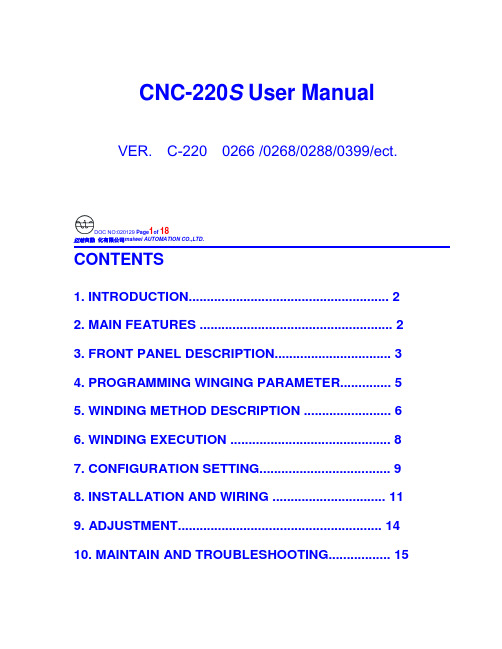
CNC-220S User Manual VER. C-220 0266 /0268/0288/0399/ect.DOC NO:020129 Page1of 18迈维自動化有限公司maiwei AUTOMATION CO.,LTD.CONTENTS1. INTRODUCTION (2)2. MAIN FEATURES (2)3. FRONT PANEL DESCRIPTION (3)4. PROGRAMMING WINGING PARAMETER (5)5. WINDING METHOD DESCRIPTION (6)6. WINDING EXECUTION (8)7. CONFIGURATION SETTING (9)8. INSTALLATION AND WIRING (11)9. ADJUSTMENT (14)10. MAINTAIN AND TROUBLESHOOTING (15)迈维自動化有限公司maiwei AUTOMATION CO.,LTD.1. INTRODUCTIONCNC-220S is a series of COIL WINDING MACHINE CONTROLLERdeveloped by MAIWEI AUTOMATION . It not only retains all the features ofprevious designs, it also has a low noise level and is less sensitive to externalpower fluctuation.CNC-220S also features an integrated design: putting stepper motor driver,DC motor speed controller, brake and power supplier control circuits into onecontrol box, simultaneously achieving size reduction, high performance andlow cost.CNC-220S Series offers CNC-220S “Standard Model” and CNC -220S EXD"External Connection Model”, depending on whether a close -loop driver isprovided for various applications.2. MAIN FEATURES◆ Single chip DSP Microprocessor design, has further higher performance and higher functions; it also has less sensitive to external power fluctuation orto external electromagnetic interference.◆ Memory capacity capable storing up to 0- 1000 steps winding data, 9 winding parameters, and 5 options can be independentlyassigned for each step. Off-power memory retention without battery.◆ Winding speed can be specified using the front panel keypad, resulting ineasy programming of multi-step, multi-speed settings.◆ Guiding traverse shaft stepper motor with a constant-current driver offeringfast wire guiding speeds.◆ Power input AC100V~120V 、220V~240V 600VA(max).迈维自動化有限公司maiwei AUTOMATION CO.,LTD.3. FRONT PANEL DESCRIPTION3.1. Power switchPower:Power supplier equipped, controls the AC power to the controller.3.2. Key pads0-9:10 key, for entering numerical values.『QTY SET』:Enter into EDIT mode.『EDIT』:Specify target production quantity.『START STEP』:Specify starting step in memory.『END STEP』:Specify ending step in memory.『DATA SEL』:Select parameter to be programmed, or to switch display mode. 『FEED DIR』:Select guiding direction for each step.『WIND DIR』:Select winding direction for each step.『EDGE STOP』:To specify whether to suspend winding when the guiding traverse moves to the two edges of the width.『AUTO HOME』:Select whether to have auto-positioning function for each step. 『AUTO START』:Select whether to have auto-starting function for each step. 『-』:Reduce step number by one, or reduce PIECE COUNTER by one.『CLR』:During programming, clear current data to zero.『COPY』:Copy the data of previous step into current step.『ENT』:Write data into memory.『RPM』:Switch display to shows PIECE COUNT or RPM.『ZERO』:Hold down this key for two seconds to reset PIECE COUNTER to zero. 『AUTO』:To switch between AUTO and NON-AUTO mode.『BRAKE』:Switch whether brake will be applied to the win spindle during stopping.迈维自動化有限公司maiwei AUTOMATION CO.,LTD.『NEXT』:Skip current step and go to the next step.『PREV IOUS』:Discard current step and go to the previous step『RESET』:At any time, discontinues current operation and return to ready mode. 『STOP』:Pause during winding.『START』:Restart during pause, or pause during winding.←:guiding traverse moves to the left.→:guiding traverse moves to the right.:Show the current step number being wound or beingprogrammed.:During programming, in combination with LED, shows the parameter being programmed. During winding or ready mode, show thecurrent number of turns or show the guiding traverse shafts position.Shows PIECE COUNT or RPM.3.4. Status indicators□READY: lit means in READY mode, flash means PAUSE mode ,not litmeans winding or programming in progress.□RUN: lit means winding in progress; not lit means not in progress.□SLOW: during winding, lit means low speed winding; not lit means high speed winding.□MOVE: lit means guiding traverse is fixing the starting position forwinding or is returning to the home position.□O.S: lit means winding operation is over speeding, guiding traverseand winding spindle shaft are out of synchronization.□LAN: lit means currently communicating with network.□FINISH: will lit when reaching the preset piece count.□ RPM: lit means the PIECE COUNT DISPLAY shows RPM.□ QTY: lit means the PIECE COUNT DISPLAY shows the piece count.3.5. Winding parameters definitions□SHIFT : Starting position of the guiding traverse.[Setting range 0.00~ 999.99 mm].□WIDTH : The traverse of the copper wire led by the traverse duringwinding. [Setting range 0 ~999.99 mm].□PITCH : Diameter of the copper wire. [Setting range 0~ 9.999mm].□TURNS: Total number of turns to be wound.[Setting range 0.0~9999.9 or 0~99999 turns].□S.SLOW : Number of turns to be wound at low speed, when start winding.[Setting range 0~999.9 turns].□E.SLOW : Number of turns to be done at low speed prior to stopping.[Setting range 0 ~999.9 turns].□H.S.: High winding speed. [Setting range from 0~99%].□L.S. : Low winding speed. [Setting range from 0~25%].□FUN : Winding complete output signal setting.4. PROGRAMMING WINGING PARAMETER4.1. MEMORY RANGE SELECTIONCNC-220S contains 1000 memory step, By defining the region, users caneffectively manage the memory. Various winding parameter can be stored indifferent regions and can be retrieved instantaneously. After specifying theregions, programming and winding can be done in those regions; allun-selected regions will retain their original contents and unmodified. Whensetting the STEP number, the Ending step number must be larger than theStarting step number, or the winding operation will not startSpecifying starting stepIn ready mode, press to select. [Setting range 0 ~ 999].Specifying ending stepIn ready mode, press to select. [Setting range 0 ~ 999].4.2. Programming winding parameterIn “READY” mode, press invokes the programming mode. First the“START STEP” number will shows at “Procedures displayer”, the parameter indicator 『SHIFT』will lit, the starting position will shows at “Documents dispayer”. The starting position can be changed to the new position by pressing thenumerical keys followed by the key.After that the STEP number will automatically increase by one, to continue setthe starting position for next step. When the STEP number larger then the“END STEP”number, the STEP number will restore to the “START STEP”number and the indicator light will change from『SHIFT』to 『WIDTH』foruser to specifying the width for each STEP. Repeat the same procedure using numerical keys and the key, all winding parameters for each STEP canThe following functions are also available::To select guiding direction, forward or reverse.:To select winding direction, clockwise or counter-clockwise.:To specify whether to suspend winding when the guiding traversemoves to the two edges of the width.:To select whether guiding traverse returns to the starting positionautomatically or upon a manual pressing of the key.:Select whether to have auto-starting function for each step.:Clear the current value to zero.copy:Copy the content of the previous step to the current step.—:Go back to the previous programming step.:To scroll through different parameters.Each time when change the PARAMETER or OPTIONS, key mustpressed to effect the change.4.3. Guiding traverse shaft introduce settingDuring set the 『SHIFT』, 『WIDTH』and 『guiding traverse travel limit』,can use numeric keypad to set location data or can also use ,←or→keysTo leading the guiding traverse shaft location.4.4. Clear all winding parameterIn the”READY”mode, press will clear all the winding parameter inthe memory. Be cautious in using this function or all the data will be lost. 5. WINDING METHOD DESCRIPTIONPrior to winding, the general winding principles are explained below so the operators can have a better understanding of the performance of the controller and make better use of it.5.1. Counting mode(Refer to the section 7.1. Counting mode).◆Absolute counting modeWinding spindle shaft is capable of fixed-point stopping. Upon each restart,the turn count will reset only the integer portion of the turn’s to zero, with the decimal unchanged. For example, for a previous number of 100.3 turns, when restarting the next step winding, the counting will start with 0.3 turn to avoid accumulation of spindle shaft free play error from consecutive windings. This counting method may cause insufficient winding by one turn. Therefore, when starting from 0.5~0.9, the spindle will turn to the 0.0 before it starts counting.◆Relative counting modeThis counting method zeros the counter upon each restart, therefore it is easy to understand and will not cause insufficient winding.5.2. Wire-guiding mode◆Interlace wire-guidingIf the『幅宽』of the step is zero, the wire-guiding becomes interlace mode. When it begins winding, the wire-guiding will follow the wire direction to proceed two wire diameters and regress one wire diameters cyclically until the step of winding ends. This mode especially suits the inductor winding.◆Non wire-guidingSometimes, the winding device may be used to winding adhesive tapes or copper foil. When the wire-guiding is not needed, 『PITCH』may be adjusted to zero and the wire-guiding won't be move.5.3. Operation mode(Refer to the section 7.1. Operation mode).◆Single click modeWhen press the start switch, the motor start winding, and when you releasethe start switch, the motor stop winding immediately.◆Double click modeWhen press the start switch, the motor start winding, and if you want to pause the motor, you have to release the start switch then press it again.5.4. Running mode◆Continual modeBefore it begins winding, if『SHIFT』of the step set as 999.99, then the starting position, the width , the wire-guiding direction and the winding direction won't be re-read. The values are not changed, that is the wire guiding will continue guiding wires on the same position. The width and left-right margins are the same as the ones of the previous section. Both the wire-guiding and winding directions are not changed either. This mode especially suits to winding which have the multiple drawing tops in the same sets of coils.◆Edges slow modeThe winding speed will slow down before the guiding traverse reach to the two edges of the width (work with『E.SLOW』turns). After the guiding traverseCNC-220S USER MANUAL VER. Page 8 of 18迈维自動化有限公司maiwei AUTOMATION CO.,LTD.veered, then restore to hi-speed winding. (Refer to the section 7.1. edge slow mode).◆Automatically circularly modeIf key set to on, it means Automatically circularly mode, in this modewhen finish a step of winding it will automatically get into next step and start winding without press key (work with and keys).5.5. How to Correct setting turns◆Preset methodSet the 『E.SLOW』to zero first and then set the 『TURNS』to the desired number. Set proper parameters according to copper wire, bobbin, tension, etc, then press to start winding. When finished, obtain the actual number ofturns and calculate the number of overshot turns. Go into programming modeand subtract the number of the overshot turns from the 『TURNS』to obtainthe required setting.This method has a higher throughput, however, the resulting stopping location may not be precise.◆High-Low speed methodThis method uses a combination of 『H.S.』/『L.S』and 『E.SLOW』to achieve the desired number of turns.The『L.S.』should not be too high. The number of 『E.SLOW』turns must be adequate to allow the spindle shaft to slow down to low speed before reachingthe total number of turns. This can result in precise stopping location.◆Double-brake methodAs the winding turns of the winding shaft reach the numbers of the『E.SLOW』, brake for a short period first. After the winding shaft stops, continue winding atlow speed. Therefore the numbers of the slow speed may be reduced and the efficiency of winding may be increased, (Refer to the section 7.1. braking mode).6. WINDING EXECUTION6.1. To start windingAfter set up all data items, press key,the winding process begins in accordance with the set-up content. Press key to pause winding. During winding, press the key, the winding speed can be switch between highspeed and low speed.The following key functions are available during PAUSE mode::Give up the numbers of the winding turns and regress one step.:Finish current step and proceed to next step.CNC-220S USER MANUAL VER. Page 9 of 18迈维自動化有限公司maiwei AUTOMATION CO.,LTD.Continue winding.: Give u p winding and go back to the”READY ”mode.6.2. Change the display modeDuring winding or during PAUSE mode, press key, the“Documents displayer ” can be change the display mode between turns or guiding traverse position.6.3. Winding speed (RPM) displayPress ing key will cause the”QTY displayer ” to display the spindleshaft “RPM ” without interrupting the counting. Pressing again will change the“QTY displayer ” back to displaying the piece count.6.4. Piece counter managementUpon turning on the “POWER ”, “QTY displayer ” will showsthe number of piece produced. During wining, each time the CONTROLLERgoes from the “Stert step ” to the “End step ”, the piece counter willautomatically increase by one.◆ Preset piece counterIn “ready ” mode, press key once and key in desired values followedby the key. When the “QTY displayer ”reaches the preset value, theFINISH led will lit. [Setting range 0~99999].◆ Decrease piece counterDuring “READY ”or PAUSE mode, press the key and hold down for twoseconds the piece counter will decrease by one.◆ Reset piece counterIn any time holding down key for two seconds, it will set the piececounter to zero.7. CONFIGURATION SETTINGCNC-220s is a multi-purpose design, to meet various requirements;additional settings are configured to provide flexibility for additionalapplications.In the “READY ” mode, press the following keys combination as section[7.1.~7.8], the “Documents displayer ” will show corresponding setting value. If no change is necessary, press the key get back to “READY ” mode. Orpress key to get into change mode, then the parameter can be changed bypressing the numerical key followed by the key. 7.1. Winding mode selection 『EDIT 』 『DATA SEL 』In this function the STEP display and the DATA display will shows eight digits, representing eight winding mode selections respectively.Press numerical keys as below to set each digit.CNC-220S USER MANUAL VER. Page 10 of 18邁維自動化有限公司maiwei AUTOMATION CO.,LTD.7 6 5 4 3 2 1 :The guiding traverse moving speed.0 represents high speed ; 1 represents low speed.2 Moving increment :The travel increment of the guiding traverse.1 represent 0.01mm (4 mm per revolution).2 represent 0.02mm (8 mm per revolution).3 represent 0.01mm (5mm per revolution).4 represent 0.04mm(16 mm per revolution. 3Counting mode :Select the counting mode of the winding spindle shaft. 0 represents with zero point and using absolute counting mode.1 represents without zero point and using relative counting mode. 4Edge slow :Slow down the winding speed before the guiding traverse reach to the two edges of the width.0 represents not slow down ; 1 represents to slow down. 5Braking mode :Select the braking mode of the winding spindle. 0 represents single brake mode ; 1 represents double brake mode. 6Counting unit :Select 0.1 or 1 turns as your count unit. 0 represents 0.1(0.0 to 9999.9 turns); 1 represents 1(0 to 99999 turns). Guiding traverse unit :Select the basic unit of guiding traverse.0 represents mm; 1 represents inch (must using lead screw in imperial). Operation mode :Select operation mode for the START switch.0 represents Single click mode ; 1 represents Double click mode.The key on the front panel always as the Double click mode.7.2. Password 『EDIT 』 『DATA SEL 』 2This password is used to protect the setting data in memory. After you set this password, you cannot change any winding parameter and configuration data in normal sequence. You have to key in four numbers of password before press the ,『ENT 』『START STEP 』,『END STEP 』,『QTY SET 』 keys. If the password has been passed once, youcan change any data in normal sequence until you turn off the power or press key. You must to remember the password or you cannot change any data.[Setting range 0000~9999]. Set 0000 means no password.7.3. Travel limit 『EDIT 』 『DATA SEL 』 3Set the maximum travel distance of guiding traverse. During winding when the guiding traverse reaches this position, the motor stop winding immediately,and the “Documents displayer ” shows error massage, then “RESET ” and goback to the“READY ” mode. [Setting range 000.00~999.99]. 999.99 Means no limit. 7.4. Fixed location 『EDIT 』 『DATA SEL 』 4To set how often, must be correct the guiding traverse location. Each time when finish this number of product pieces, the guiding traverse will moves to the home position to correct the location before moving to starting position. [Setting range 00~ 99]. Set 00 means not to do this function.7.5. Limited winding speed 『EDIT 』 『DATA SEL 』 5 This value is to limited winding speed and make sure the winding spindle shaft and guiding traverse are in synchronization. The controller uses this value to calculate with wire PITCH of current step, and then to limited maximum winding speed of current step.[Setting range 0~ 99999]. Set 0 means no limit speed.7.6. Brake holding time 『EDIT 』 『DATA SEL 』 6 To set the hold times for brake. [Setting range 0.1~9.9 sec].7.7. Acceleration times 『EDIT 』 『DATA SEL 』00 means shortest acceleration times ;99 means longest acceleration times. 7.8. Deceleration times 『EDIT 』 『00 means shortest deceleration times ;99 means longest deceleration times.8. INSTALLATION AND WIRING◆The controllers should be operated in an environment that is protected from moisture, corrosive gases, or liquid, and free from airborne dust, metallic particles, and magnetic noise.◆Do not block the intake/exhaust ports of the controller. Otherwise, a fault may occur.◆Make sure that the power source supplies the correct voltage and is capable of supplying the required current to the controllers.◆Do not connect or disconnect wires and connectors while power is applied to the controller.Make sure the machine and controllers are properly grounded. Make sure that the leads and connectors are connected correctly.◆Normally operate under 10℃ ~ 40℃ environment ; over 40℃ should perform under good ventilation, avoid heating.8.2. Wiring diagram for CN3~CN6FOOT SWITCH Operate Switches Home Sensor Turn Counter AUX I/O邁維自動化有限公司maiwei AUTOMATION CO.,LTD.8.3. Wiring diagram for CNC-220SAC Input DC90-180V/90-400W DC24V 12W 2Phase 6V 2ADC MOTOR BRAKE STEP MOTOR Drive STEP Motor in directlyAC Input Motor Driver DC24V 12W 2Phase 6V 2ABRAKE STEP MOTOR External connect STEP Motor driver邁維自動化有限公司maiwei AUTOMATION CO.,LTD.AC Input Motor Driver DC24V 12W Step Motor DriverBRAKE9. ADJUSTMENT9.1. Adjustments for CNC-220SACC: Acceleration timesRotate ACC to set the accelerate times for the winding spindleCL:Output current limit.1. Connect a DC Amperes meter between terminal and DC motor as below.2. In ready mode press to make the DC motor starting rotate andthen press to holding the winding spindle.3. Rotate CL to set limited current, show on Amperes meter.( 2A for 180v DC motor、4A for 90v DC motor).(The CL have been set by factory before delivery. Only adjust it when change DC motor and replace 220-DVR driver board.)IR:Torque compensation.1. Set the winding parameter “H.S”、”L.S”. in 20, then press to change the DISPLAY shows RPM. Then press key to start winding.2. Rotate IR potentiometer to make it in same speed during the winding spindle shaft in full-load and unload. Then press key to stop winding.MAX:Maximum winding speed.3. Set the winding parameter“H.S”、”L.S”. in 99, and press key to change the DISPLAY shows RPM. Then press key to start winding.4. Rotate MAX potentiometer to make the winding speed (RPM) as you wantThen press key to stop winding.CNC-220S CNC-220S EXD9.2. Adjustments for CNC-220S EXDSpeed Mode selectionTo select the speed signal output mode for winding driver.Selected by JP1.1. Vout mode:Represents the speed signal with DC 0~10v output.2. H/L mode:Represents the speed signal with HI/LOW lever output.Hi speed with HI lever, low speed with LOW lever.Vout adjust1. Set the winding parameter “H.S”、”L.S”.in 99, and press“MAX” key to change the DISPLAY shows RPM. Then press key to start winding.2. Rotate Vout potentiometer to make the winding speed (RPM) as you want.Then press key to stop winding.3. This function only worked in Vout mode.110.MAITAIN AND TROUBLESHOOTING110.1. Periodically maintain◆Please periodically clean up the controller inner accumulate dust and dopants.◆Please periodically check the wire connection between controller and machine if have loose or bad contact.◆The following parts must be maintained or changed periodically as listbelow. If any part is found faulty, it must be changed immediately evenwhen it has not yet reached the end of its life, which depends on theoperating method and environmental condition.◆For parts replacement, please contact your sales representative.10.2. Error messageWhen a fault occurs during operation, the DATA DISPLAY shows errormassage, stop wi nding and then “RESET”go back to the “READY” mode.Err-0:The parameters or data in memory are fault.Err-1:The『SHIFT』value sets exceed the Travel Limit.Err-2:During winding, the guiding traverse to exceed the Travel Limit.Err-3:During winding, the guiding traverses reach to the Home sensor.10.3. To abort seeks the original positionAt boot and reset procedures, if because of unknown reason howeverengender the winding shaft and guiding traverse can't find out the originalposition and make the controller can't get into ready mode, can press keyto abort seeks the original position, make controller get into ready mode.10.4. TroubleshootingThis section provides information to guide the user in understanding differentfault condition and their general troubleshooting procedures, and with their possible solutions.◆Do not connect or disconnect wires and connectors while power is appliedto the controller.◆Make sure that the leads and connectors are connected correctly, beforedoing the troubleshooting procedures.◆Do not remove welded parts on the PC board without appropriate tools.CNC-220S USER MANUAL VER. Page 17 of 18邁維自動化有限公司maiwei AUTOMATION CO.,LTD.CNC-220S USER MANUAL VER. Page 18 o18邁維自動化有限公司maiwei AUTOMATION CO.,LTD.。
Intel Agilex 时钟和 PLL 用户指南说明书

Intel® Agilex™时钟和PLL用户指南针对Intel® Quartus® Prime设计套件的更新:20.3本翻译版本仅供参考,如果本翻译版本与其英文版本存在差异,则以英文版本为准。
某些翻译版本尚未更新对应到最新的英文版本,请参考英文版本以获取最新信息。
在线版本ID: 683761内容内容1. Intel® Agilex™时钟和PLL概述 (4)1.1. 时钟网络概述 (4)1.2. PLL概述 (4)2. Intel Agilex 时钟和PLL架构和功能特性 (5)2.1. 时钟网络架构和功能特性 (5)2.1.1. 时钟网络架构 (5)2.1.2. 时钟资源 (7)2.1.3. 时钟控制功能 (8)2.2. PLL架构和功能特性 (10)2.2.1. PLL功能特性 (10)2.2.2. PLL使用 (11)2.2.3. PLL位置 (12)2.2.4. PLL架构 (12)2.2.5. PLL控制信号 (13)2.2.6. PLL反馈模式 (14)2.2.7. 时钟乘法和除法 (18)2.2.8. 可编程相移 (19)2.2.9. 可编程占空比 (19)2.2.10. PLL级联 (19)2.2.11. PLL输入时钟切换 (20)2.2.12. PLL重配置和动态相移 (24)2.2.13. PLL校准 (24)3. Intel Agilex 时钟和PLL设计考量 (26)3.1. 指南:时钟切换 (26)3.2. 指南:时序收敛 (27)3.3. 指南:复位PLL (27)3.4. 指南:配置约束 (27)3.5. 指南:I/O PLL重配置 (27)3.6. 时钟约束 (28)3.7. IP核约束 (28)3.8. 指南:使用从LVDS SERDES Intel FPGA IP来的tx_outclk端口,实现f OUT_EXT≥ 300Mhz的5%占空比 (28)4. Clock Control Intel FPGA IP核 (29)4.1. Clock Control Intel FPGA IP的发布信息 (29)4.2. Clock Control IP核参数 (29)4.3. Clock Control IP核端口和信号 (30)5. IOPLL Intel FPGA IP核 (31)5.1. IOPLL Intel FPGA IP的发布信息 (31)5.2. .mif文件生成 (31)5.2.1. 生成一个新的.mif文件 (32)5.2.2. 对现有.mif文件添加配置 (32)5.3. IP-XACT文件生成 (32)内容5.3.1. 生成一个新的IP-XACT文件 (32)5.4. IOPLL IP核参数 (32)5.4.1. IOPLL IP核参数:PLL选项卡 (33)5.4.2. IOPLL IP核参数:Settings选项卡 (35)5.4.3. IOPLL IP核参数:Cascading选项卡 (36)5.4.4. IOPLL IP核参数 - Dynamic Reconfiguration选项卡 (36)5.4.5. IOPLL IP核参数 - Advanced Parameters选项卡 (37)5.5. IOPLL IP核端口和信号 (37)6. Intel FPGA IP核 (39)6.1. IOPLL Reconfig Intel FPGA IP的发布信息 (39)6.2. 实现IOPLL Reconfig IP核中的I/O PLL重配置 (40)6.2.1. IOPLL与IOPLL Reconfig IP核之间的连接 (40)6.2.2. 连接IOPLL和IOPLL Reconfig IP核 (40)6.3. IOPLL Reconfig IP核重配置模式 (41)6.3.1. .mif流重配置 (41)6.3.2. 高级模式重配置 (42)6.3.3. 时钟门控重新配置 (43)6.3.4. 动态相移重配置 (43)6.4. IOPLL Reconfig IP核中的Avalon Memory-Mapped Interface端口 (43)6.5. 地址总线核数据总线设置 (44)6.5.1. 高级模式重配置的地址总线和数据总线设置 (44)6.5.2. 针对时钟门控重配置的输出时钟和相应数据位设置 (50)6.5.3. 针对IOPLL Reconfig IP核动态相移的数据总线设置 (51)6.6. 设计实例 (51)6.6.1. 重配置选项:使用IOPLL Reconfig IP核的.mif流重配置 (52)6.6.2. 重配置选项:使用IOPLL Reconfig IP核的高级模式重配置和重新校准 (52)6.6.3. 重配置选项:使用IOPLL Reconfig IP核的时钟门控重配置 (53)7. Intel Agilex 时钟和PLL用户指南存档 (54)8. Intel Agilex 时钟和PLL用户指南文档修订历史 (55)1. Intel® Agilex™时钟和PLL概述1.1. 时钟网络概述Intel® Agilex™器件包含将信号分布到整个架构的专用资源。
控制器安装说明书

控制器安装说明书控制器(英文名称:controller)是指按照预定顺序改变主电路或控制电路的接线和改变电路中电阻值来控制电动机的启动、调速、制动和反向的主令装置。
由程序计数器、指令寄存器、指令译码器、时序产生器和操作控制器组成,它是发布命令的“决策机构”,即完成协调和指挥整个计算机系统的操作。
控制器的分类有很多,比如LED控制器、微程序控制器、门禁控制器、电动汽车控制器、母联控制器、自动转换开关控制器、单芯片微控制器等。
在这里重点介绍的是电动汽车控制器的工作原理。
电动汽车控制器是用来控制电动车电机的启动、运行、进退、速度、停止以及电动车的其它电子器件的核心控制器件,它就象是电动车的大脑,是电动车上重要的部件。
电动车主要包括电动自行车、电动二轮摩托车、电动三轮车、电动三轮摩托车、电动四轮车、电瓶车等,电动车控制器也因为不同的车型而有不同的性能和特点。
一、高标科技电动车控制器安装步骤:首先确定电源正负极,和电门锁线:方法是先把万用表打直流档上,再把万用表的负极[黑线]接在电池的负极上[地线],然后用万用表的正极[红线]一个一个量,有电压的是正极[稍微比电源电压高点]。
无电压的是负极,这里说明一下,有电源是三根线,其中那跟是电门锁线,这根线的特点是,打开钥匙和电源电压一样,关上钥匙没电压。
其次关上钥匙连接电源线和电门锁线这三根线:控制器电源线粗红色的是正极,粗黑色的是负极。
接好后打开钥匙,再量量电源电压和电门锁线的电压是不是正常,然后在分别量转把线的电源电压5V左右[红黑线],霍尔线的电源电压5V左右[红黑线][别忘了万用表打到直流档上]。
第三各个电压正常对接白色学习线:若反转拔开在对接一次,电机正转后拔开学习线。
接转把线,一般按颜色接就可能了,若还不可以有可能转把坏掉了,那么拔掉转把线,直接连接控制器转把线的红线和绿线。
电机正常转,证明转把有问,换个转把。
第四电机正常转后,刹车断电线,霍尔线,仪表线等等。
FAB2 系列智能控制器用户手册说明书
序言序言感谢您选购了本公司FAB2使用前花些时间阅读一下本手册,您将会更方便地使用本产品。
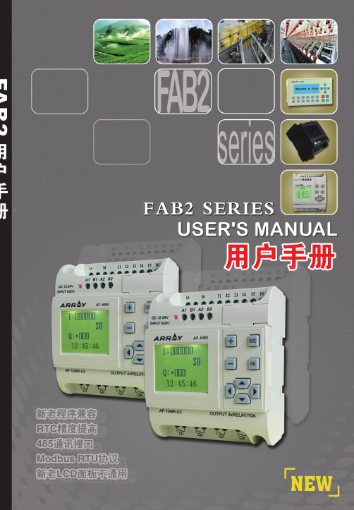
FAB2系列智能控制器是一种采用功能块(FBD)LCD液晶显示面板的智能控制器。
它将以往PLC工作大大地简化。
FAB2生活的每个空间。
本手册将详细介绍FAB2用方法。
注意:(1)不得影印或转载本手册全部或部分内容。
FAB2 Intelligent Controller目录目录第一章F A B2简介1.1 FAB2的结构 (1)1.2 规格型号 (2)1.3 FAB2特点 (3)第二章F A B2的安装与接线2.1 FAB2的安装 (5)2.1.1 FAB2的安装方法 (5)2.1.2 FAB2的安装尺寸 (5)2.2 FAB2的接线 (6)2.2.1 FAB2的电源接线 (6)2.2.2 FAB2的输入接线 (7)2.2.3 FAB2的输出接线 (8)第三章功能模块概述3.1 基本功能模块(GF) (11)3.1.1 AND (12)3.1.2 OR (13)3.1.3 NOT (13)3.1.4 NAND (14)USER'S MANUAL3FAB2 Intelligent Controller目录4.3.1.3 FAB2_Addr 读写/修改地址界面 (38)4.3.2 Set 设置界面 (38)4.4 编辑FAB2功能程序 (39)4.4.1 编程规则 (39)4.4.2 中间继电器 (40)第五章通讯连接5.1 FAB2 的下载口 (43)5.2 FAB2 的485 接口 (43)5.2.1 FAB2 的A1B1 接口 (43)5.2.1 FAB2 的A1B1 接口 (43)5.3 FAB2通讯模块使用说明 (45)第六章应用6.1 学校上课或者工厂上班铃声的控制 (47)6.2 楼梯、大厅或者走廊照明多功能开关 (49)6.3 自动门控制要求 (49)6.4 通风系统 (50)6.5 霓虹灯控制系统控制要求 (51)6.6 展示橱窗照明系统 (54)6.7 FAB2在楼宇管理中的应用 (55)6.8 FAB2在二极管耐压计数及包装流水线上的引用 (56)USER'S MANUAL5FAB2 Intelligent Controller目录3.1.6 帮助 (72)3.1.7 编辑 (72)3.1.8 搜索 (72)3.1.9 FAB2操作 (73)3.1.10 窗体 (73)3.2 工具栏 (74)3.2.1 标准工具栏 (74)3.2.2 控制工具栏 (74)3.3 模块库 (75)3.3.1 模块库操作 (77)3.3.2 模块分类 (77)3.3.3 模块属性的设置 (77)3.3.3.1 通用属性 (77)3.3.3.2 特殊属性设置 (78)第四章基本操作4.1 开启文档 (86)4.1.1 开启新文档 (86)4.1.2 开启原有文档 (87)4.2 编写功能图程序 (88)4.2.1 放置模块 (88)USER'S MANUAL7FAB2 Intelligent Controller目录2.6 AF-10MR-E2/AF-20MR-E2 (114)2.7 AF-10MT-GD2/AF-20MT-GD2 (115)附录3 保用说明 (117)附录4 关于USB驱动说明 (119)USER'S MANUAL9FAB2 Intelligent Controller第一章 FAB2简介第一章 FAB2简介FAB2系列PLC 是老FAB 系列PLC 的升级版,它也采用功能块FBD (Function Block Diagram)的方式编写程序,比起传统的PLC 编程(梯形图和指令)更为简单易学。
讯维电源时序器 Power Timing Z8 可编程强电控制系统安装使用手册说明书
中文版XUNWEI安装使用手册www.xunwei.tm绪言感谢您购买和使用XUNWEI的产品在使用本机前请细阅这本用户手册以便能正确使用并且请妥善保存这本手册万一有不了解或故障时这本手册会带给您很大的帮助。
开关量控制,可级连到244台设备前面板带红色电源指示和红色继电器开关指示灯具有手动和中控同时管理功能设备可以安装到标准机柜断电复位功能设备可以顺序开,反序关,具有时序器功能XW-Z8可编程强电控制系统(XUNWEI Programmable Standard Voltage Control System)是最新开发的高科技产品,是继单纯面板硬件控制和单纯计算机软件控制之后的第三种控制方式既有简单面板又有计算机软件或中央控制系统集中管理的理想升级换代产品。
设备电源时序开关控制应用范围:配套XW系列中控、CRESTRON、AMX等中控系统产品用于礼堂、报告厅、大中型高档会议室、多功能厅控制所有的会议室多媒体设备(包括声、光、电、像)自动化控制及其他控制。
第一章、设备使用注意事项为确保设备可靠使用及人员的安全,请在安装、使用和维护时,请遵守以下事项:1、在设备安装时,应确保电源线中的地线接地良好,请勿使用两芯插头,。
确保设备的输入电源为220V50Hz的交流电。
2、当电源开关处于关的状态时,机箱内的电源线仍然带电,非专业人员请勿随意打开机箱,以免发生触电事故。
3、不要将电源时序器设备置于过冷或过热的地方。
4、电源时序器在工作时会发热,因此要保持工作环境的良好通风,以免温度过高而损坏机器。
5、阴雨潮湿天气或长时间不使用时,应关闭设备电源总闸。
6、非专业人士未经许可,请不要试图拆开设备机箱,不要私自维修,以免发生意外事故或加重设备的损坏程度。
第二章、绪言感谢您购买和使用本公司的XW(控制)产品。
在使用本机前,请细阅这本用户手册,以便能正确使用。
并且请妥善保存这本手册,万一有不了解或故障时,这本手册会带给您很大的帮助。
时序控制器说明书
时序控制器操作說明一、 用途顺序时间控制器是用于使用阀针式热流道系统时,用以控制模具热咀注塑时间先后的设备。
顺序时间控制器能使热流道系统的各个浇口得以控制,具有以下优势:·使成形产品表面引发瑕疵的熔接痕消除,或重新设置产品表面熔接痕的位置,从而达到改善成形产品的质量;·通过对每一个浇口的注射量的调节,达到改善品质,以防产品瑕疵出现或产品填充未到位等现象的发生;·受时间控制器的控制,所有的浇口并不是同时开放,故注塑可在最小锁模力的情况下进行;·通过浇口处注射率的提高,使产品流痕达到最佳状态。
二、电源配置主电源输入单相交流电95-240VAC50/60HZ注射信号输入直流24VDC、交流110V/220V、开关信号可选电磁阀电压直流24VDC、交流110V/220V、操作温度范围(-10 - +50度)PCB结构 1.PCB主板 2.显示PCB板时间控制器电源注塑信号输入,注射信号输出。
切换信号输入,状态显示。
三、面板操作說明A —蜂鸣器B —A模式指示灯C —B模式指示灯D —显示关闭时间E —显示开启时间F —关闭指示灯G —打开指示灯H —待机指示灯J —设定值调节功能键(上)K —设定值调节功能键(下)I —手动键L —参数设置键M —电源开关键N —模式信息对照表二.时序控制器操作步骤。
1.按ON/OFF键打开时序控制卡电源,2.功能参数设置,1>A/B模式设置按住MODE SET键1秒进入参数设置,上端显示器会显示A-B,下端显示器显示模式A或B,通过按上键或下键可调整为B模式或A模式;按按住MODE SET 键1秒可退出参数设置。
2>0.1与0.01秒定时分辨率选择按住MODE SET键1秒进入参数设置,上端显示器会显示A-B,下端显示器显示模式A或B,然后再点击MODE SET键1次,此时上端显示器会显示dot, 下端显示器分辨率0.01或0.1,通过按上键或下键可调整分辨率为0.1或0.01;按住MODE SE T键1秒可退出参数设置。
斯波尔安Level-Master控制器说明书
for Valve TypesP-H-M-V-W-D-AThe SPORLAN Level-Master Control is a positive liq-uid level control device suitable for application to all flooded evaporators.The LMC is a standard thermostatic expansion valve equipped with a Level-Master Element. The combina-tion provides a simple, economical and highly effective liquid level control. The bulb of the conventional ther-mostatic element has been modified to an insert type of bulb which incorporates a low wattage heater. A 15 watt heater is supplied as standard. For applications below -60°F evaporating temperature specify a spe-cial 25 watt heater.The insert bulb is installed in the accumulator or surge drum at the point of the desired liquid level. As the level at the insert bulb drops, the electrically added heat in-creases the pressure within the thermostatic element and opens the valve. As the liquid level at the bulb rises, the electrical input is balanced by the heat transfer from the bulb to the liquid refrigerant and the LMC either modulates or eventually shuts off. The evaporator pres-sure and spring assist in providing a positive closure.The Level-Master control can be applied on any system that has been specifically designed for flooded operation.Sporlan is not responsible for system design and, there-fore is not liable for any damage arising from faulty de-sign or improper piping, or for misapplication of its prod-ucts. Figures 2 through 8 are piping schematics only to illustrate possible methods of applying the LMC valves.If these valves are applied in any manner other than as described in this bulletin, the Sporlan warranty is void. The system piping should be designed to protect the compressor at all times. This includes protection against overheating, slugging with liquid refrigerant,and trapping oil in various system locations. Sporlan recommends that recognized piping references, such as equipment manufacturers’ literature and the ASHRAE Handbooks be consulted for assistance.The valve is usually connected to feed into the surge drum above the liquid level. It can also feed into the liquid leg or coil header.The insert bulb can be installed directly in the shell, surge drum or liquid leg on new or existing installations. Existing float systems can be easily converted by install-ing the LMC insert bulb in the float chamber.The Level-Master Control may be installed at any ambi-ent temperature. A thermostatic switch in the heater assembly protects the element from the excessive tem-perature created by the heater.The insert bulb should be installed at the point where the liquid level is to be maintained. The bulb must be in contact with the refrigerant, i.e., NOT installed in a well. If the insert bulb is projected directly into the surge drum, it should be shielded from possible splash from either the valve feed or the return from the coil. While generally in-stalled in a horizontal position, see Figure 1, it will operate effectively at any angle or vertical position.Minor adjustments in liquid level can be made with the expansion valve adjustment stem. The insert bulb assem-bly is provided with a lock ring and gasket joint so the bulb can be removed without breaking the pipe joint.GeneralInsert BulbDESCRIPTION and OPERATIONFOR USE ON REFRIGERATION and/or AIR CONDITIONING SYSTEMS ONLYThe heater comes with a two wire neoprene covered cord two feet in length. It runs through a moisture-proof grommet and a 1/2” male conduit connection af-fixed to the insert bulb assembly, see Figure 2.On installations where the valve is isolated from the surge drum by a hand valve, and a 2 to 3 pound pressure drop from the valve outlet to the bulb location is likely, we recommend using an externally equalized valve.General - All reciprocating compressors allow some oil to pass into the discharge line along with the dis-charge gas. Mechanical oil separators are used exten-sively; however, they are never completely effective. The untrapped oil passes through the condenser, liquid line, expansion device and finally into the evaporator. In a properly designed direct expansion system, the refrigerant velocity in the evaporator tubes, and in the suction line, is high enough to insure a continuous re-turn of oil to the compressor crankcase. But, this is not characteristic of flooded systems. Here we purposely design the surge drum for a relatively low vapor veloc-ity to prevent entrainment of liquid refrigerant droplets and consequent carry over into the suction line. This design prevents oil from returning to the low side in the normal manner.If oil is allowed to concentrate at the insert bulb loca-tion of the Sporlan Level-Master Control, overfeeding with possible floodback can occur. The tendency tooverfeed is caused by the fact that oil does not convey the heat from the low wattage heater element away from the bulb as rapidly as does pure liquid refrigerant. The bulb pressure is higher than normal and the valve remains in the open or partially open position. Oil and Ammonia Systems - Liquid ammonia For flooded chillers that do not use a surge drum, a sump with a drain valve is usually provided at the bot-tom of the chiller shell.The above methods are quite satisfactory, except on some low temperature systems, where the drain leg or sump generally has to be warmed prior to attempting to draw off the oil since the trapped oil becomes quite viscous at lower temperatures.Electrical ConnectionsHand ValvesOil ReturnFigure 4TYPICAL INSTALLATIONPAGE 2If oil is not drained from a flooded ammonia system a reduction in the evaporator heat transfer rate can oc-cur due to an increase in the refrigerant film resistance. Difficulty in maintaining the proper liquid level with any type of flooded control can also be expected.With a float valve you can expect the liquid level in the evaporator to increase with high concentration of oil in a remote float chamber.If a Sporlan Level-Master Control is used with the inset bulb installed in a remote chamber, oil concentration at the bulb can cause overfeeding with possible flood-back. The lower or liquid balance line must be free of traps and must be free draining into the surge drum or chiller as shown in Figure 4. The oil drain leg or sump must be located at the lowest point in the low side. Oil and HFC/HCFC Systems - With HFC and HCFC systems - Refrigerants 134a, 22, 507, etc, the oil and refrigerant are miscible under certain conditions. Mineral oil is partially miscible in liquid R-22 and POE lubricant tends to be more miscible in R-134a and R-507 and other HFC refrigerants. In R-22 systems, a 5% (by weight) of napthenic mineral oil in liquid refriger-ant will remain in solution to approximately 0°F. But at temperatures below 0°F a liquid phase separation occurs. An oil rich solution will appear at the top and a refrigerant rich solution will lie at the bottom of any relatively placid remote bulb chamber. Keep in mind miscibility data for systems using R-22 and HFC refrig-erants depends on the oil used and the percentage of oil present in the refrigerant.In HFC systems, the miscibility of the POE oil depends on the oil approved for the system. Different POE oils will yield different results. POE oils formulated with low-er molecular weight alcohols tend to be more miscible than those with higher molecular weights. Depending on the system,the POE lubricant and refrigerant can be completely miscible at all temperatures normally en-countered, or some liquid phase separation could exist for a particular POE oil/ refrigerant combination.Oil in flooded evaporator applications can produce many effects. Oil as a contaminant will raise the boiling point of the liquid refrigerant if it exists in significant quantity in the evaporator. Oil can change the heat transfer properties with a consequent loss in system capacity. In addition, oil can affect the liquid level con-trol and produce “foaming”, potentially carrying liquid into the suction line.With a float valve you can normally expect the liquid level in the evaporator to decrease with increasing concentration of oil in the float chamber. This is due to the difference in density between the lighter oil in the chamber and lower balance leg, and the heavier refrig-erant/oil mixture in the evaporator. A lower column of dense mixture in the evaporator will balance a higher column of oil in the remote chamber and piping, in a manner similar to a “U” tube manometer with a differ-ent liquid in each leg.With the Sporlan level Master Control the heat trans-fer rate at the bulb is decreased producing overfeed-ing and possible flood back. In order to minimize that, we must keep the oil concentration as low as possible in the evaporator, surge drum, and remote insert bulb chamber - if one is used. With HFC/POE oil systems, the oil/refrigerant mixture is likely homogenous (but not necessarily) and you can drain from almost any lo-cation in the chiller,surge drum, or remote chamber that is below the liquid level. With R-22 or a possible HCFC/POE oil mixture that is not homogenous, the drain must be located at, or slightly below the surface of the liquid since the oil rich layer is at the top. There are many types of oil return devices:1. Direct drain into the suction line.2. Drain through a high pressure liquid warmedheat exchanger.3. Drain through a heat exchanger with the heat sup-plied by an electric heater.The following Figures 5, 6, 7, and 8 are representative of these three methods.Draining directly into the suction line, as shown in Fig-ure 5, is the simplest method but the hazard of possible floodback to the compressor remains.DIRECT DRAIN - of oil to the suction line isone of three ways to recover oil in flooded sys-tems. Heat from the environment or a liquid-suc-tion heat exchanger is required to vaporize theliquid refrigerant so drained. Vapor velocitycarries oil back to the compressor.Draining through a heat exchanger as indicated in Figure 6, is a popular method since liquid refrigerant floodback problems are minimized by using the warm liquid to vaporize the liquid refrigerant in the oil/re-frigerant mixture.The use of a heat exchanger with an insert electric heater, as shown in Figure 7, is a variation of the pre-ceding method.In all of the oil return arrangement discussed a solenoid valve should be installed in the drain line and arranged to close when the compressor is not in operation. Oth-erwise liquid refrigerant could drain from the low sideinto the compressor crankcase during the off cycle.PAGE 3PAGE 4OIL RETURN - by draining oil-refrigerant mix-ture through a heat exchanger is illustrated here. Heat in incoming liquid vaporizes refrigerant to prevent return of liquid to compressor. Liquid feed is controlled by a hand expansion valve.If the insert bulb is installed directly into the surge drum or chiller, then oil return from this point only is necessary. However, if the insert bulb is located in a remote chamber which is tied to the surge drum or chiller with liquid and gas balance lines then oil return should be made from both locations as shown in Fig-ures 5, 6, and 8.ELECTRIC HEATER - may also be used to sepa-rate oil and refrigerant. This system is similar to that of Figure 6 except that heat required for vaporization is added electrically.Conclusions - The problem of returning oil from a flooded system is not highly complex and there are undoubtedly other methods in use today that are com-parable to those outlined above. Regardless of how it is accomplished, oil return must be provided , for proper operation of any flooded system – not only with the Sporlan Level-Master Control but with a float or other type of level control device.Manual CrankcaseFigure 7Figure 8SD-28-705© Copyright 2005 Parker Hannifin Corporation, Washington, Missouri。
GOYEN TBMM时序脉冲控制仪 说明书
技术说明书 TBMM 时序脉冲控制仪概况:高原公司的GC1200(带盒子)和TBMM(线路板)系列清灰 系统控制器是专为操作脉冲 除尘器阀门而设计的首选系列。
控制器提供连续信号给控制清灰脉冲频率和间隔的电磁阀以设定清灰时间。
以TBMM 电路板为基础的微处理机结合控制器程序的数字显示,能独立调节: o 阀门“通电”时间 o 阀门“停电”时间 o 工作的阀门数量 o 除尘器停止过滤后的吹净周期数(自动吹净功能)适用范围:适用于除尘器,特别是逆吹风脉冲清灰过滤系统包括各种滤袋、滤筒、扁袋、陶瓷管和金属纤维滤袋。
结构标准的GC1200 密封盒是用聚碳酸酯做成,为电子组装件提供总体安全保护,达到IP65 (Nema 4) 的保护等级。
客户也可以选用具有同等 保护功能 的金属密封盒。
TBMM 数显电子计时器已经被有关部门验证而且厂家提出保证, 决不会影响其他电子设备的安全运作。
GC1200 控制器是很结实的装置, TBMM 线路板表面已经过一种特殊处理,可经受高湿度、高温度环境。
各组件均经过严格挑选,可以隔离电子信号噪音,并具有输入电源超压保护和输出信号超载保护功能。
控制器具有自动吹净功能,计时器在除尘器风机停止后能继续运行,以完成整个预设定的程序周期。
当风机停止后,风机马达 启动器上的 辅助接触自动打开,开始吹净周期。
吹净周期的程序编制数为0~25。
当预编程序的周期数完成后,计时器就自动停止。
当除尘器风机再次开启后,吹净功能计时器也会自动开启。
图1 阀门控制技术参数输入电压 100-260 Vac 操作温度: -40℃至+60℃ 输出电压 与主供电匹配负荷输出指示器: 红色 LED控制接头数10, 20, 30, 40, 50 预编程序设定选择器: 三位数字电子显示器(LED) 阀门“通电”时间: 30~350 毫秒,每次可调节5 毫秒 吹净周期数: 0~25阀门“停电”时间: 5~180秒,每次可调节1秒 密封盒:铭牌 IP65/Nema 4 国际标准保护 功率负荷: 2.5 Amp, 100~260 Vac 材料:粉末涂层金属(M)或聚碳酸酯(P)定时精确度:定点的正负5%GC1200/GC1300/GC1400宽 度 高 度深 度安装孔尺寸 控制盒尺寸大小 英寸 mm 英寸 mm 英寸 mm 宽mm×高mm 聚碳酸酯10输出口11 180 7.5 180 5.12 90 120×120 聚碳酸酯20~50 输出口15 380 11 280 5.12 130 354×254 金 属10 输出口 12 300 7.87 200 4.72 120 —— 金 属20-50输出口15380123006.10155——接线:请按照接线图连接。
- 1、下载文档前请自行甄别文档内容的完整性,平台不提供额外的编辑、内容补充、找答案等附加服务。
- 2、"仅部分预览"的文档,不可在线预览部分如存在完整性等问题,可反馈申请退款(可完整预览的文档不适用该条件!)。
- 3、如文档侵犯您的权益,请联系客服反馈,我们会尽快为您处理(人工客服工作时间:9:00-18:30)。
Contents
1、Environments …………………………………………………2 2、Composition of Control Module …………………………… 2 3、Central Processing Unit ………………………………………2 4、Input …………………………………………………………….2 5、Display………………………………………………………… 3 6、Output …………………………………………………………3 7、Start to Run ………………………………………………… 4 8、 Menu Setting ……………………………………………….…5 9、Wiring Specification…………………………………………… 7
to confirm.
a. Right digit in DEL panel blinks.
b. Set time using
.
c. Move between digits using
,
d. Hit to save, or keep idle for 4 seconds to automatic save. 8)Set OPEN time
2)Power LED is blinking while power on.
3)Press
a. POWER LED blinks
b. Display delay time value and open time value at each display panel.
4)Switch between MODE A/MODE B and gate off.Press
Move using
to get gate and its OPEN panel,
a. Right digit in OPEN panel blinks.
b. Set time using
.
c. Move between digit using
.
d. Hit
to save, or keep idle for 4 seconds to automatic save.
Connect to main input power, signal input from injection machine, output to mold.
Make sure the main input voltage (see rear of time case), output voltage to mold.
e. Move using
between GATE.
f. When move, MODE A or B LED is Blinking in the gate.
g. Press
to save, or keep idle for 4 seconds to automatic save.
h. When gate off, all display is off (MODE A/B LED,DEL/OPEN display panel off) 5)Switch between units(999/99.9/9.99)
up the open time and displays it in OPEN display panel. e. When injection signal is off ,delay set time will be display in DEL display panel, and
OPEN display panel displays counted open time until next injection signal comes on.
Move the gate using
, and press
for 4 seconds to confirm.
a. Buzzer rings and MODE LED Blinks.
b. “Unl” displays in DEL panel and 999 “or 99.9/9.99” display in OPEN panel.
c. Switch units using
.
d. Move gate using
.
e. Hit
to save, or keep idle for 4 seconds to automatic save.
6)Manual open
i): ALL OPEN
a. It keep open while ii):A gate OPEN
b. To set unit of each gate(999/99.9/9.99)
a. To open manually a gate or all gate.
POWER
a. To turn On/Off time
5、Display 1)Display delay time and open time of each gate in display panel. 2)Display LED on while output on. 3)Display MODE A or B of each gate with LED. 4)Display output voltage(DC240V or AC220V)to Solenoid Valve with LED. 5)Display LED on while signal on.
Sequence Injection Controller Version 3.0
Sequence Injection Controller
MANUAL TYPE MDS-808
English
USER’S MANUAL
Sequence Injection Controller Version 3.0
1
USER’S MANUAL
Sequence Injection Controller Version 3.0
1、Environments 1)Main Power Input:AC220V(50-60Hz) 2)Signal Input Power:DC24VorAC220V 3)Solenoid Valve Output Power:DC24V(Less than 100mA pet GATE)or AC220V(Total less than 1A)
to confirm.
8、Menu Setting 1)MODE A
i) Example a. In case injection signal =10sec and DEL time =4sec, then after DEL time, it opens
(Relay ON) for 6sec. b. For the delay time, it counts down and displays it in DEL display panel, and just after
Thank you for using our production
Before using the product ,please read this instruction manual carefully to avoid any damage due to improper usage. If you have any questions, please do not hesitate to contact our company technologist.
injection signal comes on, after DEL time, it opens for OPEN time (4sec). b. For the delay time, it count down and displays it in DEL display panel
a. Buzzer rings and mode LED blinks.
b. MODE LED of 1st gate blinks.
c. Hit
to switch MODE A/B and gate off.
d. MODE A or B LED blinks,Both MODE A and B LEDs blink when gate off.
DEL time, it opens (Relay ON). c. In case injection signal is off before delay time passed, it resets to set time. d. Even after DELAY time passed, injection signal is keeping on, it opens, and it counts
pressed.
a. Move using
,
to get gate.
b. It keeps open the gate while
pressed.
4
USER’S MANUAL
Sequence Injection Controller Version 3.0
7)Set DET time:
Move using Direction Key to get gate and its DEL panel,
5
USER’S MANUAL
2)MODE B
Sequence Injection Controller Version 3.0
Example a. In case injection signal=10sec, DEL time=4sec, and OPEN time=4sec, then when
A GATE8DEL OPEN
A
ENTER
4
B
B