BDCOM 1705_2605_2613_3605 All-in-One综合宽带路由器宣传彩页_v2.1
无线WiFi-BDCOM WSC6100-X256B配置手册
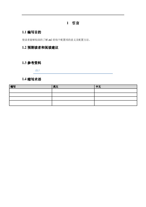
1引言1.1编写目的使读者能够较深的了解AC的每个配置项的意义及配置方法。
1.2预期读者和阅读建议1.3参考资料《X》1.4缩写术语2ACWEB登陆用网线连接PC和AC本地管理口,修改本地连接为自动获得IP地址;在浏览器地址栏中输入AC的IP地址后回车,弹出如下登陆界面:输入正确的用户名、口令后及验证码后,点击按钮即可登陆ACWEB管理界面,如下图所示:左侧栏为导航栏,点击配置树的相应节点可进入相关的配置界面,配置树主要分为四项配置内容,分别是:系统配置,系统管理,运行信息查询,WEB服务管理。
右侧为主显示窗口,可使用多标签页方式来显示当前的配置界面。
默认有【基本信息预览】和【快速配置向导】和【高级配置向导】三个标签页。
【基本信息预览】可查看当前AC概要信息,接入AP信息,接入用户信息,系统告警列表,AP设备管理,AP动态信息,用户注销的信息。
【快速配置向导】为主要开局配置项的快捷方式,如下图所示。
按按钮后弹出如下页面:此时设备的默认ESSID:bdcomGeneric加密方式修改成了WEP形式。
【高级配置向导】为主要开局配置项的快捷方式,如下图所示。
步骤一:AC端口IP配置在航栏中选择【步骤一:AC端口IP配置】,进入如下视图:选中条目点击按钮可修改该端口配置,点击按钮可刷新该端口配置。
选中要修改的端口类型,单击按钮或双击要配置的条目,弹出视图如下:可以修改接口配置:修改IP地址配置和地址池配置。
当启动DHCP服务时,就会在DHCP地址池配置中默认增加个名称为POOL_LAN0网关为192.168.0.1的一个地址池。
查看接口状态:步骤二:配置DHCP在导航栏中选择【步骤二:配置DHCP】进入如下视图:默认有两个条目AC分给AP的地址池POOL_LAN0,AP分给STA的地址池POOL_VLAN0。
具体如下:步骤3:无线业务(ESS)配置在的导航栏中选择【步骤3:无线业务(ESS)配置】,进入如下界面:如果AP是W AP2100-K机器默认的ESSID是bdcombdcom-wap2100-k;如果AP是W AP2100-SK机器默认的ESSID是bdcombdcom-wap2100-sk;如果不是这两种机型,默认的ESSID是bdcomGeneric。
DOM0000010 空气净化器系统说明书

PART NO. DOM0000010 INSTALLATION AND MAINTENANCESPECIFICATIONSSERVICE REQUIREMENTS: Air: minimum 60 psig (4 bar), maximum 116 psig (8 bar) at 5.0 CFM (140 dm3/m). Clean, dry, non-lubricated. Supply air must be 5 PSIG (0.3 bar) greater than inlet pressure for pressure transmitters (optional) to read properly.Electrical Controller: 115 VAC / 230 VAC (factory set) at 50/60 Hz.Motor: 220/380/480/575 V 50/60 Hz – 3 Phase. ¼ Horse Power Motor Load is 1.1 full load amps at 220VAC, 0.6 full load amps at 480VAC CONNECTIONS: Air: ¼” NPTIINSTALLATION INSTRUCTIONS1) This filter system is equipped with one motor per station that rotates ashaft that provides force to move the cleaning disc while a rotary typecylinder actuates the purge valve. Connect the air supply lines (customersupplied) to the inlet port (1/4” NPTI) of the solenoid stack mounted on the control panel.2) Connect the incoming single-phase electrical supply for the controller tothe panel mounted disconnect switch inside the automation enclosure.Please reference the units wiring diagram for the proper terminalconnections for the line and neutral wires. Ground connects to the ground terminal mounted on the face of the switch.3) Connect the incoming three-phase electrical supply for the motors to thepanel mounted disconnect switch inside the automation enclosure. Please reference the units wiring diagram for the proper terminal connections forthe line and neutral wires. Ground connects to the ground terminalmounted on the face of the switch.INSTALLATION CHECKLISTComplete this checklist before operating the system:☐Verify that the input power wiring is attached correctly to the main disconnect switch mounted inside the enclosure.☐Verify that the incoming automation electrical supply is the proper voltage.Improper voltage will cause serious damage to the filter’s electricalsystems. The proper voltage for the controller is factory set at 115 volts or 230 volts (single phase VAC).☐Verify that the incoming motor electrical supply is the proper voltage.Improper voltage will cause serious damage to the filter’s electricalsystems. The proper voltage is factory set at 220, 380, 480 or 575 volts(three phase VAC).START-UP VERIFICATION and OPERATIONBefore circulating fluids through the filter system, start the system dry and verify the following:1) Turn the controller power switch to the ON position (located on theenclosure door). Along with the illumination of the GREEN (power status)light, the display should show the main screen (image 1).2) Turn the motor power switch to the ON position (located on the enclosuredoor).3) Touch the ON/OFFbutton (lower left hand corner of screen). The status box on Image 1 will change from OFF to ON. The motor will also begin to start up one at a time. This prevents a large power surge, which wouldresult from trying to start all the motors at one time. After all the stations have been sequentially started, they all run independent of each other. 4) Touch the Purge button. The status box should now show PURGE. Theoptional purge header butterfly valve will open, the purge valve for the first station will open. After the purge duration the first station purge valve will close and this sequence will continue for all remaining stations. Theoptional header flush valve will flush the purge header. After the cycle is complete the status box will return to ON.Image 1: Display showing main screenImage 2: Display showing parameter adjustment screen ON Controller is OnDP DP switch has hit it set pointPURGE Purging Cycle is runningEXCESS DP Fault Due to High DPFAULTFault Due to Purge header valve or motorfailure. Check system status screen.OFF Controller is Off (See warning box below) Table 1: Status states that can be display on main screen. (For the Siemen’s Controller the states have their own display box that is grayed out when not in use. )WARNING: When the PLC is off, only the PLCcontrol is disabled. The green power light willstill be illuminated to indicate that all electricalcircuits are powered. Use caution whenworking on the system in this mode to preventelectrical shock. The ON/OFF button is notintended to be a replacement for followingproper lockout procedures.FAILURE TO FOLLOW THIS WARNING MAY LEAD TO DEATH OR SEVERE INJURY.BUTTON DESCRIPTIONSMAIN SCREENBelow is a description of each button function on the main screen (Image 1). A. ON/OFF button – See warning box to the right. Turns the PLC ON andOFF. In the event of power failure, the operator will have to turn thesystem back ON. To reset the system and clear all error messages, turn the system OFF and back ON.B. MANUAL PURGE button – Allows the operator to initiate a purgesequence. When the button is touched, PURGE will be displayed in the status box.C. PARAMETER ADJUST button – Touching this button will display thepurge sequences and motor timers.D. STATION ENABLE button – Touching this button will display the stationadjustment screen. This is where stations may be turned on or off.PARAMETER ADJUSTMENT SCREENBelow is a description of each button function on the Parameter Adjustment screen (Image 2).A. Purge Interval (min)intervals. Units are in minutes.the timed purge function.B. Purge Duration (0.1S) – Determines the amount of time that the purgevalve is open during the purge sequence. Units are in 0.1 seconds.C. Flush Duration (s) (optional) – The flush time determines the amount oftime the flush valve is open at the end of purge sequence to flush thepurge header.D. DP Delay (sec) – The DP Delay is the amount of time the system willpause after reaching the DP set point before beginning the purgesequence. While system is running the DP Delay, DP will be display inthe statue of the main screen. This time will be dependent on air andprocess pressure. Units are in seconds.E. Motor Up Max. (s) – The maximum amount of time that the motor will runin the up direction. Used to change the cleaning disc to the downdirection if the proximity switch is not sensed in the allotted time.F. MotorDown(s)- The maximum amount of time that the motor will run in the down direction. Used to change the clean disc to the up directionafter the allotted time.G. Main Screen button – Touching this button will return the user to theMain Screen (Image 1).STATION ENABLE SCREENand disable that station. Pressing the Main Screen button will return to the Main or previous set of stations.SYSTEM STATUS SCREENthe individual stations or valves. Pressing the Main Screen button will return to the Main screen and pressing Next Screen or Previous Screen button will cycle to the next or previous set of stations.For the Siemens controller (Image 4) the System Status screen will only displayeither up or down or the station is disabled. If there is a fault in the over current the motor will display FAULT. The valve with display OK if it is working anddetected see Fault Messages below.For the Allen-Bradly controller (Image 5) the System Status screen will display more detail information on the statuses of the motors, valves and proximityThe motor status will show UP if the cleaning disc is going up and DOWN if the cleaning disc is going down. TRIP will be displayed if there is an over current fault. The motor status will show OFF if the station or controller is turned off. The Prox status will show OK if it is working normally. If an OPEN or SHORT is display it mean that a fault was detected. The Prox status will show OFF if the station or controller is turned off.closed. FAULT will be display if a PHV Fault is detected see Fault Messages turned off. Image 3: Station Enable screenImage 4: System Status with an Siemens controller Image 5: System Status with an Allen-Bradley controllerO PERATIONThere are two distinct components to a DCF-2000 control system. The first is the control of the individual motors to produce the reciprocating motion of a cleaning disc required to keep the filter screen clean and move debris to the bottom of a station tube for purging. The second component is the actual purge cycle itself which moves the debris out of the system using system operating pressure and opening valves in a prescribed sequence.RUN CYCLEThe cleaning disc of an individual station is constantly cleaning the element in both directions of a reciprocating stroke. Controlling this motion uses both a sensor to determine the position at the top, and a timer to determine how far down to run the disc. The motors are initially started in the upwards direction. This lets the controller find the cleaning disc for the first time and reset the timers. A delay is performed at each end of the cycle. This allows the motors to fully stop, preventing a "slam into reverse," possibly damaging the motor. As the motor starts in the downward direction, a timer starts timing it's stroke down. When the timer times out, it stops the motor for another delay. When the motor is started in its upward direction, another timer starts. This timer is the backup or watchdog timer. It is set at slightly longer than the down timer is set at. Its purpose is to act as a safety in the event of a sensor or motor failure. If the backup timer times out before the sensor "sees" the cleaning disc, it acts as the turnaround point and sends out an alarm signal. The program is configured to run off this backup timer in the event of a sensor failure so that the unit will continue to clean the screen. However, this will run the cleaning disc assembly off the screw mechanism each cycle causing a premature drive nut failure if not corrected.PURGE CYCLEA purge cycle is used to move debris out of the DCF-2000 filter to disposalor reclamation. A purge cycle may be initiated three ways.1) The first is on a timed basis, roughly coinciding with the amount of timeit takes to fill the hemispherical bottom of a station. This is the normalmode of purge operation.2) The purge may also be manually initialed. This is done by pressing theMANUAL PURGE button . A manual purge may assist in clearingadditional debris loading due to process variances, on startup forinstance.3) A purge cycle may also be initiated by excessive differential pressuresensed by the optional differential switch. The DCF-2000 normallyoperates "flatline" or with constant, low, differential pressure. Highdifferential pressure is an indication that the filter is not functioningcorrectly. This could be caused by a system upset, worn out cleaningdiscs, or even the motors stopping for some reason.The purge cycle is essentially a sequence of valves opening and closing to move the debris out of each station, then to move it downstream to waste or reclaim. Each station is purged individually to allow the filter to remain on-line with no interruption to outlet flow. The cleaning disc continue to operate normally and independent of the purge cycle.Upon initiation of a purge cycle the statues of the controller changes to PURGE. This give a visual indication that the system is cleaning and alerts personnel around the filter that valves will be actuating.The purge header control valve is actuated open. It is given time to fully open before checking the purge header control valve safety switch, verifying an open valve. This switch must be verified open before proceeding with station purging. If this switch indicates that the purge header control valve has not opened, the cycle will be aborted and the PHV Fault is activated. If the cycle were to continue under these conditions the process fluid could be diluted or contaminated by the flush portion of the cycle.After the purge header control valve has been verified open, the first station purge valve will open for a short period of time, then close. This allows the system pressure to push the debris out of the vessel into the purge header. Each station is sequentially purged for the same period, with a delay between stations, until all stations have been purged. Next the optional flush valve opens for a predetermined time to push the debris into the drain or to reclamation. It then closes. The purge header control valve closes next, finishing the cycle. The purge interval timer is reset, and the controller statues returns to ON and timing starts toward the next timed cycle. FAULT MESSAGESBelow is a description of each fault message on the Eaton HM i operator interface. To reset the system and clear all fault messages and outputs, turn the system OFF and back ON.A. EXCESS DP – When the system initiates more than 2purging due to differential pressure within 30 minutes, afault is set and the message HIGH DP will flash on thedisplay. Possible causes: plugged elements, insufficientpurge frequency or insufficient inlet pressure to properlyclean the element.B. PHV FAULT – When equipped, the purge header valve ismonitored using a limit switch. A fault is set in the event ofvalve failure. Possible causes: Poor air supply, faultyactuator, faulty solenoid valve or failed limit switch. Note:The purge sequence is disabled when this fault ispresent.C. OVER CURRENT– Over current fault or “trip” is set whena short-circuit or excessive load is present for the motor.Possible causes: wiring issue, high or low voltage issue,the clean disc being jam in place.D. OPEN – When the proximity switch is not sensed with inthe time limit set in the Motor Up Max setting. Possiblecauses: Time limit is too short. Motor or switch hasmalfunctioned.E. SHORT – When the proximity switch is continuouslybeing sensed. Possible causes: Motor or switch hasmalfunctioned.Optional DIFFERENTIAL PRESSURE SWITCH ADJUSTMENTThe differential pressure switch senses a difference in pressure between the inlet and outlet piping. When the factory pressure preset has been reached, it triggers a cleaning sequence. The factory preset is 15 PSID (1 bar).To adjust the preset, remove the DP switch cover and turn the hex-adjusting nut. Turn it clockwise to decrease the allowable differential pressure between the inlet and outlet piping. Turn the hex nut counterclockwise to increase the allowable differential pressure between the inlet and outlet piping. One flat turn (1/6thof a turn) of the hex-adjusting nut changes the setting by approximately 2 PSID (0.14 bar).CUSTOMER INTERFACEA. GENERAL FAULT (RL1) – This relay is energized duringnormal operation. It will de-energize to indicate powerloss, system is OFF, purge header valve failure or if anexcess differential pressure condition exists (purge isdisabled if there are more than two differential pressurepurge sequences in 30 minutes). See electrical schematicfor connection details. The contact rating is 7A at 30 VDCor 110 VAC.B. REMOTE PURGE START – Supplying a momentary24VDC signal to input I:0/15 will start a purge sequence.C. PURGE IN PROCESS – Output O:0/6 will be set duringthe purge sequence.North America - HQ44 Apple Street,Tinton Falls, NJ 07724Toll Free: 800 656-3344(North America only)Voice: +1 732 212-4700Europe/Africa/Middle EastAuf der Heide 253947 Nettersheim, Germany Voice: +49 2486 809-0 Internormen Product Line Friedensstraße 4168804 Altlussheim, Germany Voice: +49 6205 2094-0 Begerow Product LineAn den Nahewiesen 2455450 Langenlonsheim, Germany Voice: +49 6704 204-0ChinaNo. 7 Lane 280 Linhong Road,Changning District,Shanghai 200335, ChinaVoice: +86 21 5200 0422Singapore4 Loyang Lane #04-01/02Singapore 508914Voice: +65 6825 1668BrazilAv. Julia Gaioli, 474 - Bonsucesso07251-500 – Guarulhos BrazilVoice: +55 11 2465 8822For more information, please e-mail us at********************or visit /filtration© 2016 Eaton Corporation.All rights reserved. All trademarks and registered trademarks arethe property of their respective owners. All information andrecommendations appearing in this brochure concerning the use ofproducts described herein are based on tests believed to be reliable.However, it is the user’s responsibility to determine the suitability for hisown use of such products. Since the actual use by others is beyond ourcontrol, no guarantee, expressed or implied, is made by Eaton as to theeffects of such use or the results to be obtained. Eaton assumes noliability arising out of the use by others of such products. Nor is theinformation herein to be construed as absolutely complete, sinceadditional information may be necessary or desirable when particular orexceptional conditions or circumstances exist or because of applicablelaws or government regulations.WARRANTYAll products manufactured by Seller are warranted against defects in material andworkmanship under normal use and service for which such products weredesigned for a period of eighteen (18) months after shipment from our factory ortwelve (12) months after start up, whichever comes first. OUR SOLEOBLIGATION UNDER THIS WARRANTY IS TO REPAIR OR REPLACE, AT OUROPTION, ANY PRODUCT OR ANY PARTS OR PARTS THEREOF FOUND TO BEDEFECTIVE. SELLER MAKES NO OTHER REPRESENTATION OR WARRANTY,EXPRESS OR IMPLIED, INCLUDING, BUT NOT LIMITED TO, ANY IMPLIEDWARRANTY OF MERCHANTABILITY OR FITNESS FOR A PARTICULARPURPOSE. WE SHALL NOT BE LIABLE FOR CARTAGE, LABOR,CONSEQUENTIAL DAMAGES OR CONTINGENT LIABILITIES. OUR MAXIMUMLIABILITY SHALL NOT IN ANY EVENT EXCEED THE CONTRACT PRICE FOR THEPRODUCT.If you are interested in ordering spare parts or having service performed onyour filter, please contact Customer Service.Eaton reserves the right to change specifications, dimensions and model designationswithout prior notice.。
MB1504中文资料

When the last bit is low level and LE is high level, data is transferred to the 18-bit latch.
Load enable input (with internal pul LE is high level (or open), data stored in the shift register is transferred to the latch depending on the
16 ØR 15 ØP 14 fP 13 fr 12 FC 11 LE 10 Data 9 Clock
ABSOLUTE MAXIMUM RATINGS (see NOTE)
Rating
Symbol
Condition
Value
Unit
Power Supply Voltage
Output Voltage Open-drain Output Output Current Storage Temperature
–Binary 7-bit swallow counter (Divide ratio: 0 to 127)
–Binary 11-bit programmable counter (Divide ratio: 16 to 2047)
• Serial input 15-bit programmable reference divider consisting of:
4
VCC
— Power supply voltage input
Charge pump output
5
DO
O The phase characteristics can be inversed depending upon the FC input.
01-配置准备(bdcom配置手册)

配置准备目录第1章配置准备 (1)1.1 交换机端口编号 (1)1.2 启动交换机之前 (1)1.3 获得帮助 (2)1.4 命令模式 (2)1.5 撤销命令 (3)1.6 保存配置 (3)第1章配置准备本文档主要描述了您在第一次配置交换机时需要熟悉的信息,包括端口编号、启动交换机之前需要的工作以及命令行界面介绍。
交换机的端口编号启动交换机之前获得帮助命令模式撤销命令保存配置1.1 交换机端口编号交换机物理端口的编号按照<type><slot>/<port>的形式,类型与名称的对照表为:接口类型名称简称10M以太网Ethernet e100M快速以太网FastEthernet f1000M以太网GigaEthernet g标配端口的扩展槽号固定为0,其它扩展槽依照自左至右的次序从1开始编号。
在同一扩展槽的端口号一律由下至上,从左至右依次从1开始编号。
如果只存在一个端口,port号为1。
注:对于各种模块内的端口,由下至上,从左至右按顺序依次编号。
1.2 启动交换机之前在你打开交换机电源开始配置之前,请确认以下几步:(1) 按照手册的要求设置好交换机的硬件。
(2) 配置PC终端仿真程序。
(3) 对于IP网络协议,首先决定IP地址规划。
1.3 获得帮助使用问号(?)和方向键,可以帮助您输入命令:输入一个问号,获得当前可用的命令列表Switch> ?输入若干已知字符,紧接着输入问号(无空格),显示当前可用的已知字符开头的命令列表。
Switch> s?输入命令,紧跟空格和问号,获得命令参数列表Switch> show ?按下up方向键,可显示以前输入的命令。
您可以继续按up方向键获得更多的命令。
按过up方向键以后,按down键,可显示当前显示命令的下一条输入命令。
1.4 命令模式交换机命令行界面可分为多种模式。
每种命令模式允许你在交换机上配置不同的组件,当前可用的命令取决于您所处的命令模式。
95365防伪网产品身份信息智能管理系统中国商品防伪查询中心 中国产品质量365防伪中心 365防伪 中国商品编码

中国商品防伪查询中心95365防伪网产品身份信息智能管理系统,是专业为企业提供产品数字身份管理方面的技术服务的第三方企业服务机构,是为品牌制造企业打造的一个全国性电信级的产品数字化综合服务信息平台。
该平台将400呼叫中心、防伪查询、防窜查询、防盗查询、积分查询、物料查询、保质期查询、保养期查询、物流溯源查询、进销存管理查询等产品身份信息管理融合在一起。
包括从全国统一的特服号码(400、800)资源与呼叫中心到产品的数字数码条码标识、会员营销积分管理系统等;可根据企业不同规模类型需求,从单一模块到整体解决方案的服务平台;企业可以按需求来定制自己的全国产品信息智能管理产品模块。
其中,部分功能模块介绍如下【400、800特服号与企业客服呼叫中心系统】400电话是全国统一、终身不变的电话,可作为企业对外永不改变的集团电话,相当于是公司的呼叫中心、企业总机,彰显企业实力的同时又能统一企业通信方式防止客户流失,是企业不可或缺的通信工具。
400电话适合做公司总机、咨询热线、售后服务热线、招商热线、会员热线、订购热线、销售热线、竟猜热线等,是全国统一呼叫中心接入号码!针对中小企业,还可以量身打造简单企业信息平台,建立大企业形象,创造立杆见影的竞争优势;针对大企业,优化企业业务流程的畅通,减少人力延迟,使服务更有效率,保证不遗失每个有价值的来电。
【企业物流防窜货管理系统】企业物流防窜货管理系统是通过物流标签中的物流码对产品进行区域确认,通过电话方式进行全国实时查询,迅速确认产品销售区域,而系统则会根据产品大小包装上不同标识间的关联关系和消费者查询电话信息,自动记录相关信息,管理人员足不出户就能在系统上了解到该商品是否窜货,从而达到预防窜货、稳定销售体系的作用。
该系统是国内最好的,也是唯一一个在线并具有二级管理功能的物流防窜货系统,即可在经销商处建立系统进行实时查询。
【企业产品防伪系统】企业产品防伪系统是以防伪标签和验证标签等的方式,通过400、 800等国家级信息平台,以电话、手机短信、网站等方式实行全国实时查询,确认物品的归属权,提高防伪性能,更进一步增加保密性,从而有效杜绝假冒伪劣,让顾客更信赖企业的产品。
毯浩伊龙系统自动化控制有限公司商品说明书

ECODRIVE DKC03.1 Drive Controller
ECODRIVE DKC03.1 Drive Controller
ECODRIVE DKC03.1 Drive Controller
ECODRIVE DKC03.1 Drive Controller
ECODRIVE DKC03.1 Drive Controller
ECODRIVE DKC03.1 Drive Controller
ECODRIVE DKC03.1 Drive Controller
ECODRIVE DKC03.1 Drive Controller
ECODRIVE DKC03.1 Drive Controller
ECODRIVE DKC03.1 Drive Controller
ECODRIVE DKC03.1 Drive Controller
ECODRIVE DKC03.1 Drive Controller
ECODRIVE DKC03.1 Drive Controller
ECODRIVE DKC03.1 Drive Controller
PDP 03VRS
DOK-ECODRV-PDP-03VRS**-FKB1-EN-P • 11.96 **********************************************************(+34)960624301
ECODRIVE DKC03.1 Drive Controller
ECODRIVE DKC03.1 Drive Controller
ECODRIVE DKC03.1 Drive Controller
Allied Automation 产品目录说明书
Wieland
safety relays and controllers, circuit protection and electrical connection
Robotunits
world class fastening and extrusion systems for machine bases, safety guarding, conveyors and linear motion
ROEQ
solutions for MiR robots
Rotomation
Socomec
fusible and non-fusible disconnect switches, manual and remote operated transfer switches, single and multi-circuit power monitoring/metering
Soft Roboticcs
pneumatic rotary actuators
Schmalz
vacuum technology for automation, clamping and lifter systems
Secomea
secure communication made easy for remote access to industrial equipment
Wago
terminal blocks and I/O modules
WEG
electric motors, drives, and controls
ON ICON 自动清洗 III 产品说明书
AUTO-purge IIIProven solutions for the power industryPrecision Airflow MeasurementAn ON I CON BrandAir Monitor’s AUTO-purge III is designed for applications where the continuous exposure to airborne particulate might impair the measurement accuracy of Air Monitor’s Combustion Air (CA) Station or VOLU-probe/SS array. When activated by an Air Monitor flow transmitter (such as the VELTRON II, MASS-tron II or VELTRON DPT-plus ) or a distributed control system, a combination of valves are operated to introduce highpressure/high volume air to the flow measurement device’s sensing ports for a short duration while simultaneously isolating the transmitter from over-pressurization. This periodic purging assists in maintaining the sensing ports of the total and static pressure manifolds in a clear, unobstructed condition.Product Description• NEMA 4X Stainless Steel Enclosure• Vortex Cooler. Requires 80-100 psi air supply • Enclosure Heater. Requires 120VAC power supply •Viewing WindowPower Capacity • 24VAC • Standard• 24VDC • Low – Model SP • 120VAC • High – Model HCOptional ConstructionDimensional SpecificationsBrass and Copper Construction • All wetted tubing, fittings, and valves constructed of copper and/or brass.• Enclosure is NEMA 4 painted steel.• External connection fittings are stainless steel FPT.Stainless Steel Construction • All wetted tubing, fittings, and valves constructed of 316 stainless steel.• Enclosure is NEMA 4 painted steel.• External connection fittings are stainless steel FPT.Standard ConstructionSequence of OperationAutomatic purging at regular field selectable intervals utilizes short duration, high pressure (up to 125 psig) air to maintain signal lines and the sensing ports of the total and static press ure manifolds in a clean, unobstructed condition. If accompanied with a VELTRON II, MASS-tron II or VELTRON DPT-plus transmitter, the last transmitted process outputs are maintained for the purge cycle. At the start of the purge cycle solenoid piloted spool valves are activated to isolate the transmitter from the process signal lines, followed by the energizing of a separate purge air solenoid valve thatallows high pressure purge air to flow to the measurement station or probe array, forcefully flushing out all particulate contaminants.At the end of the timed purge cycle the purge air valve is de-energized to shut off the supply of compressed air. After a short period to allow the pressures in the signal lines to bleed down to process levels, the spool valves are shuttled to reconnect process signal lines to the attached transmitter and active process measurement resumes.Installation GuideAccumulator Tank (strongly recommended)• Requires coalescing filter, pressure regulator, and checkvalve at the tank inlet. 120 gallons – All CA stations.120 gallons – Multiple VOLU-probes having a combinedlength greater than 10'. 80 gallons – One or more VOLU-probes having acombined length less than 10'.Line from Accumulator Tank to AUTO-purge Panel• 25' maximum length, 1/2" pipe (minimum).• Recommend locating accumulator tank as close aspossible to AUTO-purge Panel.Electrical Power Requirement• 74VA at 24VAC; 28W at 24VDC; 77VA at 120VAC.• 120VAC, 5 amp when an optional enclosure heater isinstalled.Air Requirement• 80 to 175 psig at 20 ACFM, oil and dirt free.Line Size• If the distance from the AUTO-purge Panel to the airflow measuring station or probe array is less than 25', tube size to be 1/2" O.D. with a wall thickness no greater than 0.065".• If the distance from the AUTO-purge Panel to the airflow measuring station or probe array is 25' to 50', tube size to be 3/4" O.D. with a wall thickness no greater than 0.065".• If the distance from the AUTO-purge Panel to the airflowmeasuring station or probe array is greater than 50', tube size to be 1.0" O.D. with a wall thickness no greater than 0.065".Ambient Temperature • 40ºF to 140ºF. For ranges above or below this ambienttemperature, the use of an enclosure heater and/or cooler is required.The VELTRON II ultra-low differential pressure and flow transmitter, with its 0.1% of Natural Span accuracy, is intended for the most critical and demanding industrial applications that require the utmost accuracy and long-term stability. The VELTRON II’s long list of features include: AUTO-purge management; microprocessor based configuration and calibration; four lines of process data display via the graphical LCD; four analog outputs individually configurable for 0-10VDC or 4-20mA; AUTO-zero capability; electronic re-spanning; adjustable digital low pass filter; membrane keypad interface; 10:1 turndown capability; and nine different standard and bi-polar natural spans covering a range of 25.0 to 0.05 Inches w.c.Via the addition of process temperature and pressure compensation, the ultra high accuracy VELTRON II becomes the MASS-tron II multi-variable flow transmitter. For process temperature the input is an analog signal from a remote 4-wire or loop powered tempe rature transmitter with the MASS-tron II having the capability of performing the linearization. The process pressure is measured by means of an internal absolute pressure transducer connected to the transmitter’s static pressure signal input.The CAMM is an ultra-low differential pressure mass flow transmitter designed to convert the low magnitude pressure signals generated by airflow stations or probes - plus process temperature and static pressure inputs - into multiple output signals (4-20mA, 0-5VDC or 0-10VDC) linear to mass flow, temperature, and pressure.When combined with the AUTO-purge III, the CAMM multivariable transmitter becomes theCAMS. Please refer to the CAMS brochure for additional detail on this product.P.O. Box 6358 • Santa Rosa, CA 95406 • P: 800-airflow • F: 707-526-9970 •***********************IBAM TM – Individual Burner Airflow MeasurementThe IBAM TM – Individual Burner Airflow Measurement probe is ideally suited for new or retrofit applications where a reduction in plant emissions and improvement in efficiency can be obtained through accurate measurement of burner secondary airflow. The IBAM TM probe has been designed to accurately measure in the particulate laden, high operating temperature conditions found in burner air passages.CEMS TM – Continuous Emissions Monitoring SystemAir Monitor's CEMS TM – Continuous Emissions Monitoring Systems assist in complying with the Clean Air Act’s stringent emission measurement standards and the requirements of 40 CFR 75. Air Monitor has assembled a cost effective integrated system consisting of in-stack flow measurement equipment and companion instrumentation to provide continuous, accurate,and reliable volumetric airflow monitoring of stacks and ducts of any size and configuration.CA TM – Combustion Airflow Measuring Station & VOLU-probe/SS TM Traverse Probes . Air Monitor's duct mounted airflow measurement devices have beendesigned to accurately and repeatedly measure air mass flow in power plants. The Combustion Air (CA) Station TM includes honeycomb air straightener to accurately measure in shorter straight duct runs than any other flow measurement device. The VOLU-probe/SS TM delivers accurate airflow measurement performance in the form of an insertion probe. Both devices feature Type 316 stainless steel flow sensing arrays.Engineering & Testing Services. Air Monitor offers complete engineering and testing to analyze air and coal deliverysystems. Air Monitor's field testing services use 3D airflow traversing and flow measurement systems for the highest possible accuracy. To ensure cost effective and accurate solutions, Air Monitor Power has full scale model fabrication and certified windtunnel testing is used to develop application specific products that will measure accurately where no standard flow measurement can.VOLU-probe/SS TM Stainless Steel Airflow Traverse ProbesMulti-point, self-averaging, Pitot-Fechheimer airflow traverse probes with integral airflow direction correcting design. Constructed of Type 316 stainless steel and available in externally and internally mounted versions for harsh, corrosive or high temperature applications such as fume hood, laboratory exhaust, pharmaceutical, and clean room production and dirty industrial process applications.125-501-10 (03/20)Precision Airflow MeasurementAn ON I CON BrandCAMS TM – Combustion Airflow Management Systems .The CAMS TM – Combustion Airflow Management System has been designed to reliably and accurately measure airflow in combustion airflow applications. The CAMS TM contains the microprocessor based instrumentation to measure the airflow and manage the AUTO-purge. The AUTO-purge is a high pressure air blowback system that protects the duct mounted flow measurement device from any degradation in performance due to the presence of airborneparticulate (flyash).。
Genelec 8351B 智能活动监控器操作手册说明书
8351BSmart Active Monitor Operating Manual2IntroductionThank you for choosing Genelec! Fulfilling your dreams by offering the most truthful sound reproduction has been the source of our enthusiasm since 1978. Already over one million Genelec monitors are in use around the world - welcome to our story!Genelec monitors are designed to last long our spare part support extends far into future. They are hand-built in Iisalmi, Finland, using certified sustainable methods. They are individually tested and calibrated for the highest performance. They have also all been designed for low power consumption in use and in standby.Please register your monitor atmunity. /and receive an extended five-year warranty for spare parts. For more information about our service and technical support, please visit/customer-service.System CharacteristicsEach 8351B is supplied with a mains power cable, five-meter GLM network cable and this operating manual. The Genelec 8351B is suitable for all professional monitoring applications calling for very high precision and reliability. The 8351B combines many remarkable Genelec technologies to provide the benefits of a point source and controlled directivity over an extraordinarily wide audio bandwidth. The 8351B may be oriented horizontally or vertically. Listening distances can vary from less than one meter to more than 4 meters, depending on the room size and maximum sound level requirements. Genelec Loudspeaker Manager™ (GLM™) Software and GLM User KitThe GLM software tailor-fits the 8351B to your room. It is downloadable free of charge at /glm. Check regularly for updates and new features, and consider using the cloud-based GLM services for the most up-to-date methods.A GLM User Kit, comprising a USB adapter device and measurement microphone, enables precise acoustic calibration and operation of the GLM loudspeaker management network.Minimum Diffraction Coaxial (MDC™)The minimum diffraction coaxial transducer MDC design implements a coaxial driver with unparalleled acoustic directivity control. A powerful midrange transducer surrounds a high output tweeter transducer, enabling a high resolution response extending to ultrasonic frequencies. The MDC minimizes acoustic diffraction, produces a flat frequency response on the acoustical axis, and a neutral off-axis sound character. Directivity Control Waveguide (DCW™) and Acoustically Concealed Woofers (ACW™) The 8351B has an exceptionally large Directivity Control Waveguide extending over the whole enclosure front. The midrange transducer cone forms a part of this DCW. Two woofers radiate low frequencies through openings at the enclosure edges and sum acoustically placing bass on the same acoustical axis with the coaxial transducer. This unique design enables directivity control of all audio down to low bass frequencies.Smart Active Monitoring (SAM™) Smart Active Monitors automatically tune several parametricfilters in themselves to precisely compensate for room colorations using Genelec Loudspeaker Manager (GLM) software. This enables SAM monitors to sound neutral and achieve precise stereo imaging in all acoustical environments, improving accuracy of monitoring.Audio InputsThe 8351B inputs support balanced analog line-level audio and AES/EBU digital audio. At maximum sensitivity, -6 dBu analog and -30 dBFS digital audio signals produce 100 dB SPL level at one meter distance in free space.The analog input is selected when a digital signal is not present. The digital input is selected automatically when a digital signal is present even when the signal is silent. The GLM software can select either input.When the digital audio source can adjust level, it is advantageous to lower the output level of the 8351B using the rear panel controls or the GLM Master Fader. This enables a higher output level at the source with more resolution while taking full advantage of the impressively low self-generated noise of the 8351B.An AES/EBU digital audio signal carries two channels in one cable. A channel is selected using the DIP switches or GLM software. The DIGITAL OUT carries an unaltered copy of the input, enabling daisy-chaining of up to four monitors.Power ManagementThe mains power input supports any mains voltage (100-240 VAC, 50-60 Hz) and the 8351B always delivers full power even when the mains voltage fluctuates. When powered with a generator, inverter or UPS device, we recommend filtering the mains power to remove harmonics.The energy saving function Intelligent Signal Sensing (ISS™) puts the monitor to power educed sleep mode when no signal is present. Upon sensing an input, the monitor wakes up. The function is activated using GLM software or the ISS dip switch on the monitor. With GLM the time before entering the sleep mode can be adjusted, the ISS dip switch activates a fixed 60 minute time.Setup Using The GLM™ Control Genelec recommends setting up the 8351B and other SAM monitors using GLM. This is described in the GLM System Operating Manual. Although it can be used without GLM and the network, the 8351B reaches its full potential with this method. GLM software runs on Mac or Windows computers. GLM also works as a monitor controller, for switching between sets of loudspeakers, soloing, muting, invoking calibrated levels, etc. Setup with the GLM User Kit consists of the following steps: 1. Connect a CAT5 (RJ45) cable to each monitor (and subwoofer) and finally to the GLM Adapter device (see Figure 1).2. Connect the GLM Adapter device to computer USB connector.3. Using a microphone stand, place the Genelec measurement microphone (in GLM Kit) at the listening location. Point microphone upwards. Place the microphone top at the ear3Figure 3. Connector panel detail.height for typical listener.4. Connect the microphone to the microphone input in the GLM Adapter device.5. Download and install the GLM software at the Genelec web site (). Follow instructions in the software to measure and set up your monitors.6. If you plan not to use a computer for managing monitors, store settings in monitors with GLM software (menu item “Store | Store the Current Group Settings…”).Enable stored settings by turning the DIP switch “Stored” on the monitor to ON after the network has been disconnected.The CONTROL NETWORK RJ-45 connectors are not Ethernet LAN compatible. Do not connect to Ethernet LAN.Stand-alone Mode: Setup Without UsingThe GLMYou can adjust the 8351B without GLM using the controls on the back of the monitor. These stand-alone settings are limited and provide some fundamental compensations for room acoustic effects, input selections and input sensitivity. To use, disconnect the GLM management network and set the DIP switch “Stored” to OFF position.Stand-Alone FunctionalityBass Roll-Off ControlThe Bass Roll-Off setting reduces bass level for spaces with strong low frequency reverberation. It reduces output near the4MonitorMounting Position Treble Tilt Bass Tilt Bass Roll-Off Desktop Flat anechoic response None None None None Free standing in a damped room None -2 dB None None Free standing in a reverberant room None -4 dB None None Near field ona reflective surface None -2 dB None -4 dB In a cornerNone-4 dB-4 dBNoneTable 1. Suggested Tone Control settings for some typical monitor placement positions.low cut-off. Attenuation can be selected by combining settings on one or more switches.Desktop reflection compensationThe desktop control reduces frequencies near 160 Hz by 4 dB. This compensates the boost when the monitor is placed on a meter bridge or table.Bass Tilt ControlThe Bass Tilt control offers three attenuation levels for the response below 800 Hz. This control is used when monitors are placed near wall or room corner. Attenuation can be selected by combining settings on one or more switches.Treble Tilt ControlThe Treble Tilt control adjusts the high frequencies above 5 kHz. It corrects bright or dull sound and compensates high frequency loss when a monitor is placed behind a screen.LED DisableThis switch turns off the front panel LED light.ISSThis switch activates and deactivates the ISS power saving function when the 8351B is used in a Stand Alone mode. The default time for going to power save mode is 60 minutes, but this can be adjusted in the GLM software.DigitalThe Digital switch selects the digital audio signals A and B carried in one AES/EBU cable. Turning on both switches reproduces the sum of the signals. When both are selected, a 6 dB attenuation is applied to avoid an overload.LevelThe Level switches reduce the monitor output in 10 dB steps (-10 dB, -20 dB and both switches -30 dB). The switches combine with the rotary level adjustment. The total adjustment range is 42 dB. GLM software enables wider level adjustment.StoredThe Stored switch selects between the controls on the monitor back panel (OFF position) or applying the settings stored in the monitor using the GLM software (ON position). Operating EnvironmentThis product is designed for indoor use only. The permissible ambient temperature is 15-35 degrees Celsius (50-95°F) and relative humidity 20% to 80% (non-condensing). To prevent condensation after the product has been in a cool environment, wait at least one hour before opening the packaging and connecting the mains power.Cooling of the 8351B must be ensured. The minimum clearance behind, above and on both sides of the monitor is 50 mm (2 in). When 8351B is installed in a recess, the recess space must be ventilated sufficiently to remove the heat.Mounting and Placing MonitorsMounting OptionsThe Isolation Positioner/Decoupler™ (Iso-Pod™) stand allows tilting of the monitor and isolates vibrations. As delivered from the factory, the Iso-Pod retainer spring is attached to the bottom of the enclosure for vertical orientation. If you want to use the monitor in horizontal position, remove the retainer spring and reattach it5Table 2. Monitor front panel light indications summaryColour IndicationSolid greed Normal state, normal operation Blinking greenGLM is adjusting the monitorGreen blink every 10 sec.Monitor is in an ISS power saving sleep stateRed blinkPower amplifier overload protection is active (audio is modified because of protection)Solid red Monitor is mutedYellowMonitor is not in the active (playing) groupYellow blinkingOverheat protection is active (audio is modified because of protection)to the side mounting threads (see fig. 6). Never use the iso-Pod without the retainer spring as this may cause the monitor to fall.Aim the acoustic axis of the monitor towards the listening position (see Figure 4). Place monitors symmetrically and at equal distances from the listening position. Preference should be made in placing the listening position on the left-right centerline of the room (see Figure 5). If a monitor is placed far (1.0-2.2 m, 3-7 ft) from the acoustically hard wall behind the monitor, a reflection from the wall may reduce bass output. Avoid these distances.Place monitors away from acoustically reflective surfaces. Reflections from desks, cabinets, computer monitors and such objects can colour audio and blur sound images. Place monitors on stands behind and above a mixing console as this usually improves audio compared to placing monitors on a meter bridge. Ceiling and wall mounts are available through Genelec dealers. Monitor mounts attach to four M6 x 10 mm threaded holes on the enclosure back. Consult the Genelec Accessories Catalogue at or distributor/dealer for information.Front Panel LightThe light on the front panel is normally green. Red and yellow colours indicate special situations. See Table 2.Use with SubwoofersGenelec recommends 7300 series subwoofers and the W371 Adaptive Woofer System for 8351B. Consult the on-line Genelec Product Selection Tool at .MaintenanceDo not open the monitor enclosure. Opening the monitor may lead to loss of the monitor calibration and may damage components. There are no user serviceable parts inside. Maintenance or repair can only be done by Genelec certified service.Safety ConsiderationsThe 8351B follows international safety standards. To ensure safe operation, the following warnings and precautions must be observed:• Servicing and adjustment must only be performed by certified Genelec service personnel. The monitor enclosure must not be opened.• Use the product only with a mains cable having a protective ground terminal and with a mains connection with a protective earth terminal. Failing to do so may lead to personal injury.• To prevent fire and electric shock, do not expose the unit to water or moisture.• Do not place objects filled with liquid, such as vases, on the monitor or near it.• Note that the device is not disconnected from the AC mains service unless the power cable is removed from the monitor or the mains outlet.• Free flow of air behind and around the monitor maintains sufficient cooling. Do not obstruct airflow around the monitor.WARNING!The 8351B is capable of producing sound pressure levels in excess of 85 dB, which may cause hearing damage. Sound exposure level integrated over eight contiguous hours should be limited to Leq=80dB(A) to reduce the risk of permanent hearing damage. For each 3 dB increase in this sound level, half this exposure time.GuaranteeThe Genelec 8351B is guaranteed for two years against manufacturing faults or defects altering performance. You can get an additional three-year guarantee covering spare part costs by registering your product at . Refer to your point of purchase for full sales and guarantee terms.Compliance to FCC RulesThis equipment has been tested and found to comply with the limits for a Class B digital device, pursuant to part 15 of the FCC Rules. These limits are designed to provide reasonable protection against harmful interference in a residential installation. This equipment generates, uses and can radiate radio frequency energy and, if not installed and used in accordance with the instructions, may cause harmful interference to radio communications. There is no guarantee that interference will not occur in a particular installation. If this equipment does cause harmful interference to radio or television reception, which can be determined by turning the equipment off and on, the user is encouraged to try to correct the interference by one or more of the following measures:Figure 6. Placing the Iso-Pod stand when the monitor is used in horizontal position.6Figure 7. The curves above show the horizontal directivity characteristics of the 8351B (monitor in vertical orientation).Figure 8. The curves above show the vertical directivitycharacteristics of the 8351B (monitor in vertical orientation). Figure 9. The curves above show the effect of the “Bass Tilt”, “Treble Tilt”, “Desktop Low Frequency” and “Bass Roll-Off” controls on the free field response of the 8351B.Figure 11. The curve above shows the delay variation of the 8351B as a function of frequency.Reorient or relocate the receiving antenna.Increase the separation between the equipment and receiver. Connect the equipment into an outlet on a circuit different from that to which the receiver is connected.Consult the dealer or an experienced radio/TV technician for help.Modifications not expressly approved by the manufacturer can void the user’s authority to operate the equipment under FCC rules.2020k501002005001k 2k 5k 10k Frequency HzGenelec Oy 8351BdB vs freq (Hz)10Sept 2019808590BASS ROLL OFFTREBLE TILT808590808590DESKTOP LFBASS TILTd B S P L20k501002005001k 2k 5k 10k Frequency HzGenelec Oy 8351B10Sept 2019m s 501015352025304057Figure 12. The signal path block diagram of the 8351B.Genelec Document D0160R001b Copyright Genelec Oy 9.2020. All data subject to change without prior notice.International enquiries: Genelec, Olvitie 5FIN-74100, Iisalmi, Finland Phone +358 17 83881Fax +358 17 812 267************************In the U.S. please contact: Genelec, Inc., 7 Tech Circle Natick, MA 01760, USA Phone +1 508 652 0900Fax +1 508 652 0909****************************In China please contact:Beijing Genelec Audio Co.Ltd B33 - 101Universal Business Park No. 10 Jiuxianqiao Road Chaoyang District 100015 Beijing, ChinaPhone +86 (10) 5823 2014, 400 700 1978******************************In Sweden please contact:Genelec Sverige Ellipsvägen 10B P .O. Box 2306S-127 02 Skärholmen Phone +46 8 449 5220Fax +46 8 708 7071********************** The notch and shelving filters adjustments, AutoCal and GLM manual system calibration features are part of the Genelec Loudspeaker Manager (GLM) software。
ACOPOS 8V1090.00-2 产品说明书
8V1090.00-21 General information•Modular mechanical design using plug-in modules•Integrated line filter•Integrated braking resistor•All connections are made using plug-in connectors•Integrated electronic restart inhibit2 Order dataTable 1: 8V1090.00-2 - Order dataTable 1: 8V1090.00-2 - Order data 3 Technical dataTable 2: 8V1090.00-2 - Technical data1)In the USA, TT and TN power mains are commonly referred to as "Delta/Wye with grounded Wye neutral".2)If the module is operated with a mains input voltage of 3x 230 VAC, then automatic nominal voltage detection doesn't work for the DC bus. The UDC_NOMINALparameter must be set to 325 [V] by the user in this case.3)Limit values from EN 61800-3 C3 (second environment).4)The permissible input voltage range is reduced when using motor holding brakes. The input voltage range should be selected so that the proper supplyvoltage for the motor holding brake can be maintained.5)The current consumption depends on the configuration of the ACOPOS servo drive.6)Valid in the following conditions: 400 VAC mains input voltage, nominal switching frequency, 40°C ambient temperature, installation elevation <500 m abovesea level.7)Value for the nominal switching frequency.8)If necessary, the stress of the motor isolation system can be reduced by an additional externally wired dv/dt choke. For example, the RWK 305 three-phasedv/dt choke from Schaffner () can be used. Important: Even when using a dv/dt choke, it is necessary to ensure that an EMC-compatible, low inductance shield connection is used!9)The module's electrical output frequency (SCTRL_SPEED_ACT * MOTOR_POLEPAIRS) is monitored to protect against dual use in accordance with ECregulation 428/2009 | 3A225. If the electrical output frequency of the module exceeds the limit value of 598 Hz uninterrupted for more than 0.5 s, then the current movement is aborted and error 6060 is output (Power element: Limit speed exceeded).10)OSSD (open signal switching device) signals are used to monitor signal lines for short circuits and cross faults.11)Continuous operation of ACOPOS servo drives at elevations ranging from 500 m to 2000 m above sea level is possible (taking the specified continuouscurrent reductions into consideration).12)Continuous operation of ACOPOS servo drives at ambient temperatures ranging from 40°C to max. 55°C is possible (taking the specified continuous currentreductions into consideration), but this will result in a shorter service life.4 Status indicatorsACOPOS servo drives are equipped with three LEDs for direct diagnostics:Figure 1: ACOPOS servo drives - Status indicatorsDescriptionGreen (lit)The module is operational andpresent and booted, no permanent or temporary errors).Green (blinking) 1)The module is not ready for operation.Examples:•No signal on one or both enable inputs•DC bus voltage outside the tolerance range•Overtemperature on the motor (temperature sensor)•Motor feedback not connected or defective•Motor temperature sensor not connected or defective•Overtemperature on the module (IGBT junction, heat sink, etc.)•Disturbance on networkOrange (lit)The module's power stage is enabled.Red (lit) 1)There is a permanent error on the module.Examples:•Permanent overcurrent•Invalid data in EPROMTable 3: LED status - ACOPOS servo drives1)Firmware V2.130 and higherIf no LEDs are lit, the ACOPOS servo drive is not being supplied with 24 VDC.Danger!After switching off the device, wait until the DC bus discharge time of at least five minutes has passed.The voltage currently on the DC bus must be measured with a suitable measuring device before be-ginning work. This voltage must be less than 42 VDC to rule out danger. An unlit Run LED does not indicate that voltage is not present on the device!4.1 LED statusThe following timing is used for the indication diagrams:Block size: 125 msRepeats after: 3000 msTable 4: Status changes when booting the operating system loaderTable 5: Error status with reference to the CAN plug-in module AC1101)Possible errors:- ACOPOS servo drive defect- Plug-in module defect- Plug-in module not inserted correctly in the slotTable 6: Error status with reference to the POWERLINK V2 plug-in module AC1141)Possible errors:- ACOPOS servo drive defect (plug-in module not recognized)- Plug-in module defect- Plug-in module not inserted correctly in the slot- Plug-in module functioning but not automatically recognized by the ACOPOS servo drive (old bootstrap loader)5 Dimension diagram and installation dimensionsHanging verticallyFigure 2: Dimension diagram and installation dimensions1)For proper air circulation, at least 80 mm clearance must be available above and below the ACOPOS servo drive.6 WiringFigure 3: ACOPOS 1022, 1045, 1090 - Pinout overview6.1 X1 - PinoutTable 7: X1 - Pinout1)The wiring is not permitted to exceed a total length of 30 m.6.2 X2 - PinoutTable 8: X2 - Pinout6.3 X3 - PinoutDanger!Servo drives are not permitted to be operated directly on IT and TN-S mains with a grounded phase conductor and protective ground conductor!Table 9: X3 - Pinout6.4 X4a, X4b - PinoutTable 10: X4a - Pinout1)If the holding brake is connected via an additional external relay contact (ground-in e.g. via the connections S1/S2) instead of via the internal transistor, thenthe internal quenching circuit has no effect! In this case, the customer must make sure that neither the relay contact nor the braking coil are damaged when switching off the brake. This can be done by interconnecting the coil or - better still - interconnecting the contact with a quenching circuit.Table 11: X4b - Pinout1)If the holding brake is connected via an additional external relay contact (ground-in e.g. via the connections S1/S2) instead of via the internal transistor, thenthe internal quenching circuit has no effect! In this case, the customer must make sure that neither the relay contact nor the braking coil are damaged when switching off the brake. This can be done by interconnecting the coil or - better still - interconnecting the contact with a quenching circuit.Danger!The connections for the motor temperature sensors and the motor holding brake are isolated circuits.Therefore, these connections are only allowed to be connected to devices or components with at least safe isolation in accordance with IEC 60364-4-41 or EN 61800-5-1.Caution!If B+ and B- are swapped when connecting the permanent magnet holding brakes, then the brakes cannot be opened! ACOPOS servo drives cannot determine if a holding brake is connected with reverse polarity!6.4.1 Wiring the connections for the motor holding brakeThe supply, activation and monitoring of the output for the motor holding brake can take place via the X4a connector in three different ways:Table 12: Activation for the external holding brake1)Both jumpers are already on the X4a connector delivered with the ACOPOS servo drives.2)External potential-free contacts can be connected between S1 and S2 as well as between S3 and S4. This makes it possible to activate the holding brakeusing an external safety circuit independent of the control integrated in the ACOPOS servo drive.3)The parameters are set using ParID 90 (1 ... internal monitoring active; 5 ... internal monitoring not active).4)Deactivation takes place using ParID 90 (5 ... internal monitoring not active).8V1090.00-2 6.5 X5 - PinoutTable 13: X5 - Pinout6.6 Additional protective ground connection (PE)The protective ground conductor is connected to the M5 threaded bolt provided using a cable lug.Terminal cross sectionsCable lug for M5 threaded boltTable 14: Protective ground conductor (PE) ACOPOS 1022, 1045, 1090Danger!Before turning on the servo drive, make sure that the housing is properly connected to ground (PE rail).The ground connection must be established even when testing the drive or operating it for a short time!8V1090.00-26.7 Input/Output circuit diagramFigure 4: TriggerFigure 5: LimitFigure 6: Enable8V1090.00-2Figure 7: ACOPOS 1022, 1045, 1090 - Input/Output circuit diagram。
- 1、下载文档前请自行甄别文档内容的完整性,平台不提供额外的编辑、内容补充、找答案等附加服务。
- 2、"仅部分预览"的文档,不可在线预览部分如存在完整性等问题,可反馈申请退款(可完整预览的文档不适用该条件!)。
- 3、如文档侵犯您的权益,请联系客服反馈,我们会尽快为您处理(人工客服工作时间:9:00-18:30)。
BDCOM 1705/2605/2613/3605 All-in-One综合宽带路由器
产品概述
BDCOM 1705/2605/2613/3605是上海博达数据通信有限公司采用ARM、IXP等成熟处理器,结合专业的交换芯片,为中小型网吧和企事业单位设计研发的一款性价比极高的综合型宽带路由器。
BDCOM 1705 BDCOM 2605/3605 BDCOM 1705/2605/2613/3605不仅拥有强大的数据处理能力、可灵活应用于各种主流宽带接入环境,满足多用户NAT共享上网;还可提供人性化的弹性带宽分配方案,让用户带宽资源更加有效利用。
此外,BDCOM 1705/2605/2613/3605路由器还提供上网行为管理、P2P 应用控制、VPN组网、防火墙、ARP欺骗防护和抗恶意攻击等全方位的增值功能。
BDCOM 1705/2605/2613/3605系列宽带路由器,集“多线路、NAT共享、安全、弹性限速”等特性于一身,是一套个性化的All-in-One综合解决方案;可广泛应用于网吧、企业、酒店、连锁、学校等典型场合。
主要特性
极高的稳定性和可靠性
凭借十多年的数通网络研发经验和对宽带用户需求的潜心研究,博达公司提供的宽带产品解决方案在软、硬件设计、系统健壮性等各个方面都值得信赖,能够在“高温、通风不畅、接地不良”等恶劣环境下长时间可靠运行。
强大的处理能力
博达百兆级宽带路由器采用ARM9、Intel IXP等业界成熟稳定的处理器方案,结合ASIC 专用交换芯片打造而成,具有良好的吞吐性能和极高的性价比。
为多用户、大流量情况下的NAT、VPN、P2P识别和控制、防火墙等核心功能模块的稳定高速运行提供了强有力的保障。
灵活的多WAN口接入
最大可用于四WAN口组网,支持以太网、FTTB光纤、ADSL、Cable等多种方式的接入;支持“带宽叠加”“智能选路”“主辅”等多种方案的多线路策略,可满足绝大多数的需求。
人性化的弹性限速策略
在为多用户提供宽带NAT上网服务的同时,还提供灵活的弹性限速策略:在网络带宽空闲时,自动增加每用户的带宽分配;在带宽紧张时,又保证资源平均分配,避免带宽被过度
抢占的情况。
此外,还提供了大流量主机抑制、流量突发因子、用户惩罚/抑制等辅助策略,为用户网络的管理提供了丰富的手段
丰富的行为管理策略
●基于应用层识别并控制QQ、MSN等常见IM软件,支持白名单技术,方便企业网络
管理
●基于应用层识别常见P2P应用程序,并实施阻断、限速等多种策略
●基于策略库实现对常见炒股、娱乐、购物等网站进行屏蔽
●相应策略数据库可免费在线更新
丰富的抗攻击策略
BDCOM宽带路由器具备丰富的抗攻击能力,可对ARP、IP、ICMP、TCP、UDP等各种类型的报文进行详细的统计和细致分析,发现攻击后自动阻断,并提供告警信息,使您的网络高枕无忧。
对于ARP欺骗,BDCOM宽带路由器提供了IP+MAC绑定、ARP-SCAN技术、免费ARP通告等多种手段,充分保障内网安全;若配合BDCOM专用交换机产品,还可部署DHCP-Snooping 技术,使ARP欺骗无处遁形,发现和预防率100%
完善的VPN功能
BDCOM路由器支持L2TP、PPTP、GRE、IPIP、IPSec等多种VPN协议和加密算法,为企业远程办公、移动办公和虚拟专网的建设提供了完整的解决方案。
友好的用户界面
提供简单易懂的web图形化界面,即便不是专业人士,也能轻松掌握;仅需五步,您就能把网络连通。
典型应用
酒店行业的典型应用
博达宽带路由器1705/2605/2613/3605全线产品采用业界成熟、稳定,且高性价比的通信模块,可轻松承担酒店网络的运营,能够在“高温、通风不畅、接地不良”等恶劣环境下长时间可靠运行,针对流动性大的特点,博达专门为酒店用户设计开发了PNP即插即用功能,同时支持多种策略的QoS弹性带宽控制,让酒店客人得到最佳的上网体验。
企业机构的典型应用
博达宽带路由器1705/2605/2613/3605全线产品针对企业办公特点,提供了丰富的行为管理策略,对QQ、MSN等常见的IM即时聊天软件进行识别和过滤;可对常见的P2P网络应用、娱乐、购物、股票等网站进行进行选择性的屏蔽。
同时提供全面的VPN支持,在VPN
组网时,可支持在静态IP、PPPoE动态IP接入情况下灵活实现,为企业用户复杂多变的远程组网提供了完美的解决方案。
网吧行业的典型应用
博达宽带路由器1705/2605/2613/3605全线产品针对网吧用户的需求,提供了灵活的多线路策略,利用“智能选路”可为网吧用户解决电信、网通之间的访问带宽瓶颈;利用“主辅模式”可支持多线路之间的自动备份;同时还支持人性化的弹性带宽管理,可自动检测网络的状态,在忙时按照紧缩策略限速,保证每个人都能正常上网;在闲时按照宽松策略限速,让用户畅游网络。