IP Camera User Manual(网络摄像头使用说明书-英文版)
网络摄像头指南书说明书

Quick Start GuideO8VB1WelcomeThank you for purchasing this network camera!This owner's manual is designed to be a reference tool for your system.Please read this manual carefully before operating the unit and retain it for future reference. Should you require any technical assistance, contact Speco Technologies Tech Support at1-800-645-5516Important Safeguards and Warning1. Electrical safetyAll installation and operation here should conform to local electrical safety codes.Use a certified/listed 12VDC Class 2 power supply only.Please note: Do not connect two power supplying sources to the device at the same time; it may result in device damage! The product must be grounded to reduce the risk of electric shock.Improper handling and/or installation could run the risk of fire or electrical shock.2. EnvironmentHeavy stress, violent vibration or exposure to water is not allowed during transportation, storage and installation.This product should be installed in a cool, dry place away from direct sunlight and heat sources.Do not install the product in extreme temperature conditions.Do not expose the camera to electromagnetic radiation. Otherwise it may result in CMOS sensor failure.Do not block any ventilation openings.Do not allow water and liquid intrusion into the camera.3. Operation and Daily MaintenancePlease shut down the device and then unplug the power cable before you begin any maintenance work.Do not touch the CMOS sensor optic component. You can use a blower to clean the dust on the lens surface.Always use the dry soft cloth to clean the device. If there is too much dust, use a clothWarningStatement This camera should be installed by qualified personnel only.All the examination and repair work should be done by qualified personnel.Any unauthorized changes or modifications could void the warranty..This guide is for reference only.Product, manuals and specifications may be modified without prior notice. Speco Technologies reserves the right to modify these without notice and without incurring any obligation.Speco Technologies is not liable for any loss caused by improper operation.Note:Before installation, check the package and make sure that all components are included.Contact your rep or Speco customer service department immediately if something is broken or missing in the package .dampened with a small quantity of neutral detergent. Finally use the dry cloth to clean the device.Please use a professional optical cleaning method to clean the enclosure. Improper enclosure cleaning (such as using cloth) may result in poor IR functionality and/or IR reflection. The grounding holes of the product are recommended to be grounded to further enhance the reliability of the camera.Dome cover is an optical device, please don't touch or wipe cover surface directly during installation and use, please refer to the following methods if dirt is found:Stained with dirt: Use oil-free soft brush or hair dryer to remove it gently.Stained with grease or fingerprint: Use oil-free cotton cloth or paper soaked with alcohol or detergent to wipe from the lens center outward. Change the cloth and wipe severaltimes if it is not clean enough.7213456* 1 It is recommended to install the security cap for outdoor installations .* 2 DC 12V power supply is not required if a PoE switch or injector is used to power the camera.► Connecting Network Cable① Loosen the nut from the main element.② Run the network cable (without RJ 45 connector) through both elements. Then crimp the cable with RJ 45 connector .③ Connect the cable to the hermetic connector . Then tighten the nut and the main cover .1* Before you start, please make sure that the wall or ceiling is strong enough to withstand three times the weight of the camera.① Open the mounting base and the upper cover of the junction box.② Install junction box onto the wall by using the screws provided.③Fasten the camera onto the mounting base.Mounting BaseUpper Cover④nstall the camera onto the junctionConnect the cables and then ibox as shown below.⑤ Bracket Adjustment-Loosen the fixed ring to adjust the view angle of the camera. After you get the optimum angle of view, tighten the fixed ring to complete the installation.Fixed Ring°③ In the device list, you can view the IP address, model number, and MAC address of each device. Select the applicable device and double click to open up the web viewer. You can also manually enter the IPaddress in the address bar of the web browser (it will only work with ● OperationIP Scanner can search for the device on the local network.① Make sure that the camera and the PC are connected to the same local network. The camera is set to DHCP by default.②Install IP Scanner from the CD and run it after installation.Microsoft Internet Explorer 8 and above).The login interface is shown above. Default user name is admin andpassword is 1234. After logging in, follow directions to installapplicable plugins.。
网络摄像头监控仪器用户手册快速启动指南说明书

Network Traffic Camera • User ManualBullet CameraQuick Start Guide© 2020 Hangzhou Hikvision Digital Technology Co., Ltd. All rights reserved.This Manual is the property of Hangzhou Hikvision Digital Technology Co., Ltd. or its affiliates (hereinafter referred to as “Hikvision”), and it cannot be reproduced, changed, translated, or distributed, partially or wholly, by any means, without the prior written permission of Hikvision. Unless otherwise expressly stated herein, Hikvision does not make any warranties, guarantees or representations, express or implied, regarding to the Manual, any information contained herein.About this ManualThe Manual includes instructions for using and managing the Product. Pictures, charts, images and all other information hereinafter are for description and explanation only. The information contained in the Manual is subject to change, without notice, due to firmware updates or other reasons. Please find the latest version of this Manual at the Hikvision website (https:///en/).Please use this Manual with the guidance and assistance of professionals trained in supporting the Product.Trademarks Acknowledgement●and other Hikvision’s trademarks and logos are the properties of Hikvision in various jurisdictions.●Other trademarks and logos mentioned are the properties of their respective owners.LEGAL DISCLAIMER●TO THE MAXIMUM EXTENT PERMITTED BY APPLICABLE LAW, THIS MANUAL AND THE PRODUCT DESCRIBED, WITHITS HARDWARE, SOFTWARE AND FIRMWARE, ARE PROVIDED “AS IS” AND “WITH ALL FAULTS AND ERRORS”.HIKVISION MAKES NO WARRANTIES, EXPRESS OR IMPLIED, INCLUDING WITHOUT LIMITATION, MERCHANTABILITY, SATISFACTORY QUALITY, OR FITNESS FOR A PARTICULAR PURPOSE. THE USE OF THE PRODUCT BY YOU IS AT YOUR OWN RISK. IN NO EVENT WILL HIKVISION BE LIABLE TO YOU FOR ANY SPECIAL, CONSEQUENTIAL, INCIDENTAL, OR INDIRECT DAMAGES, INCLUDING, AMONG OTHERS, DAMAGES FOR LOSS OF BUSINESS PROFITS, BUSINESS INTERRUPTION, OR LOSS OF DATA, CORRUPTION OF SYSTEMS, OR LOSS OF DOCUMENTATION, WHETHER BASED ON BREACH OF CONTRACT, TORT (INCLUDING NEGLIGENCE), PRODUCT LIABILITY, OR OTHERWISE, IN CONNECTION WITH THE USE OF THE PRODUCT, EVEN IF HIKVISION HAS BEEN ADVISED OF THE POSSIBILITY OF SUCH DAMAGES OR LOSS.●YOU ACKNOWLEDGE THAT THE NATURE OF INTERNET PROVIDES FOR INHERENT SECURITY RISKS, AND HIKVISIONSHALL NOT TAKE ANY RESPONSIBILITIES FOR ABNORMAL OPERATION, PRIVACY LEAKAGE OR OTHER DAMAGES RESULTING FROM CYBER-ATTACK, HACKER ATTACK, VIRUS INSPECTION, OR OTHER INTERNET SECURITY RISKS;HOWEVER, HIKVISION WILL PROVIDE TIMELY TECHNICAL SUPPORT IF REQUIRED.●YOU AGREE TO USE THIS PRODUCT IN COMPLIANCE WITH ALL APPLICABLE LAWS, AND YOU ARE SOLELYRESPONSIBLE FOR ENSURING THAT YOUR USE CONFORMS TO THE APPLICABLE LAW. ESPECIALLY, YOU ARE RESPONSIBLE, FOR USING THIS PRODUCT IN A MANNER THAT DOES NOT INFRINGE ON THE RIGHTS OF THIRD PARTIES, INCLUDING WITHOUT LIMITATION, RIGHTS OF PUBLICITY, INTELLECTUAL PROPERTY RIGHTS, OR DATA PROTECTION AND OTHER PRIVACY RIGHTS. YOU SHALL NOT USE THIS PRODUCT FOR ANY PROHIBITED END-USES, INCLUDING THE DEVELOPMENT OR PRODUCTION OF WEAPONS OF MASS DESTRUCTION, THE DEVELOPMENT OR PRODUCTION OF CHEMICAL OR BIOLOGICAL WEAPONS, ANY ACTIVITIES IN THE CONTEXT RELATED TO ANY NUCLEAR EXPLOSIVE OR UNSAFE NUCLEAR FUEL-CYCLE, OR IN SUPPORT OF HUMAN RIGHTS ABUSES.●IN THE EVENT OF ANY CONFLICTS BETWEEN THIS MANUAL AND THE APPLICABLE LAW, THE LATER PREVAILS.Regulatory InformationFCC InformationPlease take attention that changes or modification not expressly approved by the party responsible for compliance could void the user’s authority to operate the equipment.FCC compliance: This equipment has been tested and found to comply with the limits for a Class A digital device, pursuant to part 15 of the FCC Rules. These limits are designed to provide reasonable protection against harmful interference when the equipment is operated in a commercial environment. This equipment generates, uses, and can radiate radio frequency energy and, if not installed and used in accordance with the instruction manual, may cause harmful interference to radio communications. Operation of this equipment in a residential area is likely to cause harmful interference in which case the user will be required to correct the interference at his own expense. FCC ConditionsThis device complies with part 15 of the FCC Rules. Operation is subject to the following two conditions:1. This device may not cause harmful interference.2. This device must accept any interference received, including interference that may cause undesired operation.EU Conformity StatementThis product and - if applicable - the supplied accessories too are marked with "CE" and comply therefore with the applicable harmonized European standards listed under the EMC Directive 2014/30/EU, the LVD Directive 2014/35/EU, the RoHS Directive 2011/65/EU.2012/19/EU (WEEE directive): Products marked with this symbol cannot be disposed of as unsorted municipal waste in the European Union. For proper recycling, return this product to your local supplier upon the purchase of equivalent new equipment, or dispose of it at designated collection points. For more information see: 2006/66/EC (battery directive): This product contains a battery that cannot be disposed of as unsorted municipal waste in the European Union. See the product documentation for specific battery information. The battery is marked with this symbol, which may include lettering to indicate cadmium (Cd), lead (Pb), or mercury (Hg). For proper recycling, return the battery to your supplier or to a designated collection point. For more information see: Industry Canada ICES-003 ComplianceThis device meets the CAN ICES-3 (A)/NMB-3(A) standards requirements.Symbol ConventionsThe symbols that may be found in this document are defined as follows.Safety InstructionsTABLE OF CONTENTSChapter 1 Installation (6)Overview (6)Key Feature (6)System Requirement (6)Chapter 2 Installation (7)Device Cable (7)Install TF Card (7)Install Camera (9)Ceiling Mounting (9)Horizontal Pole Mounting (10)Vertical Pole Mounting (11)Chapter 3 Network Connection (13)Wire over the LAN (13)Activate the Camera (14)Activation via Web Browser (14)Activate via SADP Software (15)Chapter 4 Login (18)Chapter 1 InstallationOverviewBullet camera supports vehicle capture, license plate recognition, vehicle type recognition, vehicle color recognition, and multi-feature extraction of non-motor vehicles and pedestrians.It adopts deep-learning algorithm, to improve the accuracy of target behavior detection and feature recognition. It has high-performance hardware processing platform and embedded operating system with high scheduling efficiency, small size, and high stability and reliability. It can adapt to different monitoring environments with high compression ratio, flexibleprocessing, automatic white balance, automatic electronic shutter, automatic aperture, and strong light suppression.It is widely used in urban road monitoring to achieve the full target feature recognition and capture of mixed lane scenes.Key Feature●CMOS smart HD camera.●Supports H.265 or H.264 encoding.●Supports full HD real-time images with ultra-low latency and ultra-low bit rate.●Supports local storage of TF card and continuous uploading of snapped pictures.●Supports 3D digital noise reduction (DNR).●Dust-proof, drip-proof, and anti-surge.Functions may vary from different models. Please refer to actual products.System Requirement●Operating System: Win 7 and above versions.●CPU: 1.0 GHz or higher.●RAM: 1 G or higher.●Display: 1024 × 768 resolution or higher.●Web Browser: Internet Explorer 8.0 and above versions.Chapter 2 InstallationDevice CableDevice cables are as follows.Device CableInstall TF CardOpen TF card cavity.1)Loosen the 4 screws shown in the figure, and pull down the TF card cover in thedirection of the arrow shown in the figure.ScrewsPull Down TF Card Cover2)Rotate the TF card cover around the screws.ARotate TF Card CoverInsert the TF card.Put the TF card cover back.1)Rotate the TF card cover around the screws.Rotate TF Card Cover2)Press the TF card cover back in the direction of the arrow shown in the figure.APress TF Card Cover Back3)Tighten the screws to complete the installation.ScrewsTighten ScrewsInstall CameraThe camera supports multiple installation methods. This manual uses ceiling mounting, horizontal pole mounting, and vertical pole mounting as examples.Ceiling MountingAttach the mounting sticker on a suitable wall and make holes according to sticker size.Attach Mounting StickerAttach the back panel foam to back cover of the bullet camera.Attach Back Panel FoamThread the cables, install the back cover on the surface of wall, and install the screw head pressure plate on the back cover.Thread CablesInstall the camera and tighten the screws to complete the installation.Tighten ScrewsHorizontal Pole MountingInstall the hoop.1)Unscrew the hoop screws and open the hoop.2)Pull the hoop ring, shrink the hoop to the thickness of the horizontal pole.3)Install the hoop bracket on the horizontal pole.Install HoopAlign the screw holes at the bottom of the two joints under the cardan joint with the hoop, screw in and tighten the screws, and install the cardan joint on the hoop.Install Cardan JointAlign the upper section of the cardan joint with the hole in the camera, screw in and tighten the screws, and install the camera on the cardan joint.Install the CameraAlign the holes on the upper and lower parts of the cardan joint, screw in and tighten the screws, and fix the two parts together.Connect Two Parts of Cardan jointRemove the back cover of the camera, thread the pre-threaded cables into the cable box, and thread the cables.Thread CablesReinstall the back cover of the camera.Vertical Pole MountingInstall the hoop.1)Unscrew the hoop screws and open the hoop.2)Pull the hoop ring, shrink the hoop to the thickness of the vertical pole.3)Install the hoop bracket on the vertical pole.Install the back cover.Install the Rear Cover1)Thread the pre-routed cables.2)Install the back cover on the hoop bracket though screws.3)Install and fix the screw head pressure plate on the back cover though screws. Thread cables through the camera.Install Back CoverInstall the camera and tighten the screws.Tighten ScrewsChapter 3 Network Connection●You shall acknowledge that the use of the product with Internet access might be undernetwork security risks. For avoidance of any network attacks and information leakage,please strengthen your own protection. If the product does not work properly, pleasecontact with your dealer or the nearest service center.●To ensure the network security of the camera, we recommend you to have the cameraassessed and maintained termly. You can contact us if you need such service.Before you start:To view and configure the camera via a LAN, you need to connect the camera in the same subnet with your computer, and install the SADP to search and change the IP address of the camera.Wire over the LANThe following figures show the two ways of cable connection of a camera and a computer.●Directly connect the camera to the computer with a network cable.●Set camera over the LAN via a switch or a router.Network CableCameraComputerDirect ConnectionSwitchComputerCameraConnection via a Switch or a RouterActivate the CameraYou are required to activate the camera first by setting a strong password for it before you can use it. Multiple activation methods are supported. Here we take example of activation via web browser and SADP.Refer to the user manual of client software for the activation via client software.Activation via Web BrowserPower on the camera, and connect the camera to the network.Input the IP address into the address bar of the web browser, and press Enter to enter the activation interface.Activation Interface (Web)Create a password.STRONG PASSWORD RECOMMENDED– We highly recommend you create a strong password of your own choosing (using a minimum of 8 characters, including upper case letters, lower case letters, numbers, and special characters) in order to increase the security of your product. And we recommend you reset your password regularly, especially in the high security system, resetting the password monthly or weekly can better protect your product.Confirm the password.Click OK to save the password and enter the live view interface.Activate via SADP SoftwareSADP software is used for detecting the online device, activating the camera, and resetting the password.Get the SADP software from the official website, and install the SADP according to the prompts.Run the SADP software to search the online devices.Check the device status from the device list, and select the inactive device.SADP InterfaceCreate a password, and confirm it.Click Activate to activate the device.STRONG PASSWORD RECOMMENDED– We highly recommend you create a strong password of your own choosing (using a minimum of 8 characters, including upper case letters, lower case letters, numbers, and special characters) in order to increase the security of your product. And we recommend you reset your password regularly, especially in the high security system, resetting the password monthly or weekly can better protect your product.Change the device IP address to the same subnet with your computer by either modifying theIP address manually or checking Enable DHCP.Modify Network ParametersInput the password and click Modify to activate your IP address modification.Chapter 4 LoginYou can log in to the camera via web browser.Open the web browser.In the browser address bar, input the IP address of the camera, and press the Enter key to enter the login interface.Input User Name and Password.Click Login.LoginInstall the plug-in before viewing the live video and operating the camera. Follow theinstallation prompts to install the plug-in.You may have to close the web browser to install the plug-in. Please reopen the web browser and log in again after installing the plug-in.0403022000313UD18748B。
(仅供参考)IPC-网络摄像机使用手册(通用版)

网络摄像机(Network Camera)2012-3用户手册注意事项:请勿将重物至于本设备上;请勿让任何固体或液体,掉入或渗入设备内;请定期用刷子对电路板、接插件等进行除尘,在进行机体清洁工作前,请关闭电源并拔掉电源;请勿自行对本设备进行拆卸、维修或更换零件。
使用环境:请在温度-10℃~60℃,湿度小于90%的环境中放置和使用本产品;请勿将本设备暴露在多烟、多尘的环境;避免强烈的碰撞,请勿摔落机器;请保持本产品的水平安装,安装在稳定的场所,注意防止本产品坠落;请安装在通风良好的场所;仅可在额定输入输出范围内使用。
适用产品:本说明书适用于本公司各种网络摄像机系列产品,包括室内枪机系列、红外防水系列、海螺系列、半球系列、家用机器人系列等。
特别声明:本手册所涵盖的内容均参考此使用手册编写时最新的消息,当涉及的内容发生改变时,恕不另行通知。
如果您有什么疑问或需要请随时联系我们。
目录第一章产品介绍1.1 产品概述本设备是专为安防领域设计的一款优秀的数字监控产品。
采用嵌入式LINUX操作系统,使系统运行更稳定;采用标准的H.264视频压缩算法,实现了高画质、低码率的同步音视频监控;采用TCP/IP等网络技术,具有强大的网络数据传输能力和远程操控能力。
本设备可以通过网络组成一个强大的安全监控网,配合专业网络视频监控设备和平台软件,充分体现出其强大的组网和远程监控能力。
同时本品也可以本地独立工作。
适合需要网络远程监控的各种场合,如:取款机、银行柜员、超市、工厂等的网络监控。
看护所、幼儿园、学校提供远程监控服务。
智能化门禁系统。
智能化大厦、智能小区管理系统。
电力电站、电信基站的无人值守系统。
户外设备监控管理桥梁、隧道、路口交通状况监控系统。
流水线监控,仓库监管。
对道路交通24小时监察。
森林、水源、河流资源的远程监控。
机场、火车站、公共汽车站等。
1.2 产品主要功能实时监视·具备模拟输出接口可通过监视器或DVR等监控设备实现监视功能存储功能·最大支持32G TF卡(部分产品支持),实现录像抓图文件本地存放·通过客户端软件或监控平台,实现录像抓图文件远程存放·存储数据采用专用格式,无法篡改数据,保证数据安全压缩方式·音视频信号由独立硬件实时压缩,实现声音与图像保持稳定同步备份功能·客户端电脑可通过网络下载TF卡上的文件进行备份录像回放功能·实现独立全实时录像,还可同时实现检索、网络监视、录像查询、下载等·支持快放、慢放等多种回放模式·可选择画面任意区域进行局部放大网络操作功能·可通过网络(包括手机)进行远程实时监视·远程云台控制·远程录像查询及实时回放报警联动功能·报警联动录像、抓图、邮件等通讯接口·具备RS485接口,实现云台控制·具备标准以太网接口,实现网络远程访问功能及远程升级维护功能。
潮流网络IP CAMERA 系列 用户说明书

潮流网络IP CAMERA系列用户说明书非常感谢您购买我公司的产品,如果您有什么疑问或需要请随时联系我们。
本手册可能包含技术上不准确的地方、或与产品功能及操作不相符的地方、或印刷错误。
本手册的内容将根据产品功能的增强而更新,并将定期改进或更新本手册中描述的产品,更新的内容将会在本手册的新版本中加入,恕不另行通知。
安全须知此内容的目的是确保用户正确使用本产品,以避免危险或财产损失。
在使用此产品之前,请认真阅读此说明手册并妥善保存以备日后参考。
如下所示,预防措施分为“警告”和“注意”两部分:警告:无视警告事项,可能会导致死亡或严重伤害。
注意:无视注意事项,可能会导致伤害或财产损失。
警告事项提醒用户防范潜在的死亡或严重伤害危险。
注意事项提醒用户防范潜在的伤害或财产损失危险。
警告:1.请使用满足SELV(安全超低电压)要求的电源,并按照IEC60950-1符合Limited Power Source(有限电源)的额定电压为12V 直流电源供应。
2.如果设备工作不正常,请联系购买设备的商店或最近的服务中心,不要以任何方式拆卸或修改设备(未经许可的修改或维修所导致的问题,责任自负)。
3.为减少火灾或电击危险,请勿让本产品受到雨淋或受潮。
4.本安装应该由专业的服务人员进行,并符合当地法规规定。
5.应该在建筑物安装配线中组入易于使用的断电设备。
6.有关在天花板上安装设备的指示:安装后,请确保该连接至少可承受向下50牛顿(N)的拉力。
注意:1.在让摄像机运行之前,请检查供电电源是否正确。
2.请勿将此产品摔落地下或受强烈敲击。
3.在对相机进行清洁时,请使用鼓风器除去镜头或滤光片上的尘埃;使用柔软、干燥的布清洁摄像机的外表面。
对于顽固的污迹,可使用蘸有少许清洁剂的软布将其拭去,然后将其擦干。
请勿使用挥发性溶剂,如酒精、苯、稀释剂等,以免损坏表面涂层。
4.避免对准强光(如灯光照明、太阳光等处)聚焦,否则容易引起过亮或拉光现象(这并非摄像机故障),也将影响CCD寿命。
IPCAMERA使用手册

网络摄像机产品使用说明书前言感谢您使用本公司网络摄像机系列,该系列是针对网络视频监控而开发的一体化网络摄像机,包括存储网络枪机、无线存储网络枪机、网络红外半球机、网络红外防水机、网络高速球等。
采用高性能、单片SOC芯片实现集音视频采集、压缩、传输于一体的媒体处理器,标准的H.264编码算法确保了更清晰、更流畅的视频传输效果。
内嵌Web Server允许用户通过IE浏览器方便地实现对前端摄像机的实时监看和远程控制。
该系列网络摄像机适用于中小企业或家庭,以及需要运用到远程网络视频传输及监控的各种场合,本产品易于安装,操作简便。
在安装网络摄像机之前,请检查您的产品配件是否齐全。
如果包装配件有漏失,请您及时联络经销商。
物品清单:1.网络摄像机 ――――1台2.WI-FI USB网卡(选配) ――――1块3.DC12V电源适配器 ――――1件4.光盘 ――――1张说明:◆文中提到的IP Camera即网络摄像机,包括存储网络枪机、无线存储网络枪机、网络红外半球机、网络红外防水机、网络高速球等。
◆单击:指用鼠标左键点击◆双击:指用鼠标左键双击◆IP CAMERA出厂的默认管理员的用户名和密码都为admin(小写)◆默认Web端口:80(TCP),默认通讯端口:4000(TCP、UDP)声明:◆本手册所描述的内容可能与您现使用的版本有区别,如果您按照本手册使用时遇到有无法解决的问题,请与本公司的技术支持部或产品供应商联系。
◆本手册内容将不定期更新,公司有保留不另行通知的权利。
目录产品概述1、 (4)应用领域简介1.1 (4)产品简介1.2 (4)产品特性1.3 (5)产品规格1.4 (5)使用环境1.5 (6)外观和安装2、 (7)外观一览2.1. (7)存储/无线存储网络摄像机后面板连接图2.2. (7)设备安装2.3. (8)设备操作说明3. (10)搜索设备及修改网络参数3.1. (10)检查连接3.2. (12)控件安装和系统登录3.3. (12)操作指南4. (14)操作按键一览4.1. (14)配置说明4.2. (14)系统参数4.3. (15)网络参数4.4. (15)用户参数4.5. (19)音/视频参数4.6. (19)视频叠加4.7. (21)移动报警4.8. (22)探头参数4.9. (22)报警器参数4.10. (23)磁盘参数4.11. (24)录像参数4.12. (25)定时录像4.13. (26)终端参数(仅当使用枪机IP CAMERA时显示)4.14. (27)报警信息4.15. (28)系统维护4.16. (29)本地设置4.17. (30)附加说明5. (31)常用动态域名设置5.1. (31)常用路由器端口映射设置5.2. (33)常见问题解答6. (34)1、产品概述1.1应用领域简介网络摄像机通常可以应用在大型商场、超市、学校、工厂、车间等一系列公共场所,因其强大的图像处理能力,网络摄像机也可以应用于像银行、交通路口等对图像清晰度要求较高的环境里。
洛雷克 IP瞭视球摄像头说明书
NVR
2. Connect the other end of the Ethernet cable to the NVR’s PoE ports. The camera may take up to 1 minute to power up after being connected to the NVR. OR Connect the other end of the Ethernet cable to a router or switch on your network. See the NVR Instruction Manual for details on connecting the camera to your NVR.
• Point the camera where there is the least amount of obstructions (i.e. tree branches)
• Install the camera in a location that is difficult for vandals to reach
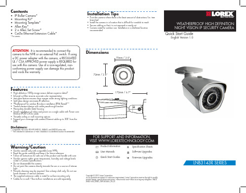
Dimensions
75mm / 3.0”
72mm / 2.8”
Features
• High definition 1080p image sensor delivers superior detail* • Infrared cut filter ensures accurate color representation • Anti-glare feature ensures clear images under strong lighting conditions • Split glass design minimizes IR reflection • Weatherproof for outdoor & indoor installation (IP66 Rated)** • Vandal resistant design with cable pass-through bracket • Heavy-duty durable metal housing • Simple installation of video and power on a single cable with Power over
MPEG4网络摄像机使用说明书

MPEG4网络摄像机使用说明书MPEG4网络摄像机使用说明书目录第一章简介 (3)第一节IP Camera简介3第二节特性简介3第三节网络摄像机的应用 (3)第二章登录IP Camera (4)第一节IPCam IP地址搜索工具 (4)第三章设置IP Camera (8)第一节状态信息 (8)第二节基本配置 (8)3.2.1音频视频设置 (8)3.2.2网络设置 (10)3.2.3拨号设置 (10)3.2.4动态域名 (11)3.2.5时间日期 (12)第三节高级配置 (12)3.3.1 维护&升级 (12)3.3.2 用户管理 (13)3.3.3 更改密码 (14)3.3.4 邮件设置 (15)3.3.5 FTP设置 (15)3.3.6 报警事件 (16)3.3.7 特殊设置 (17)第四节录像回放 (18)第五节系统信息 (18)3.5.1状态信息 (18)3.5.2日志信息 (18)第四章名词解释 (19)第一章简介第一节IP Camera简介IP Camera即IP网络摄像机。
网络摄像机是一种结合传统摄像机与网络技术所产生的新一代摄像机,它是一台可独立运作的内置网页服务器的摄像机,不需连接到计算机上,即可以将影像通过网络传至地球另一端,供用户从世界各地以网页浏览器来实时监看影像。
远端的浏览者不需用任何专业软件,只要标准的网络浏览器(如“Microsoft IE或Netscape)即可监视其影像,授权用户还可以控制摄像机云台镜头的动作或对系统配置进行操作。
其为一低成本的远程视讯监看解决方案,在远程的用户只需在网页浏览器上输入IP Camera 的IP地址或网域名,就可以实时由远程监看影像并且具有录象、拍照等功能,使用操作非常方便。
IP Camera安装也是非常容易的,可直接连上ADSL/CABLE MODEM,用PPPoE配合DDNS动态网域协议来独立使用,或上路由器或IP分享器并设定NAT功能来达成网络视讯监看功能。
IPCameraUserManual(网络摄像头使用说明书-英文版)(精)
Vilar IP Camera VS-IPC1002 User’s ManualIndex1INTRODUCTION.............................................................................- 1 -1.1W ELCOME TO THE V ILAR IP C AMERA (11.2P ACKAGE C ONTENTS (11.3I DENTIFY VS-IPC1002 (21.3.1VS-IPC1002Views....................................................................- 2 -1.3.2Indication and Operation..........................................................- 4 -2FUNCTIONS AND FEATURES........................................................- 10 -2.1B ASIC F UNCTIONS (102.2A DVANCED F EATURES (103SYSTEM REQUIREMENT...............................................................- 11 -4SETUP PROCEDURE......................................................................- 12 -4.1VS-IPC1002P OWER &N ETWORK C ONNECTION (124.2R OUTER/S WITCH/H UB/X DSL M ODEM C ONNECTION (134.3U SE IPC AM S EARCH T OOL TO SETUP VS-IPC1002 (144.4V IEW V IDEO ON W EB B ROWSER (164.5S ETUP VS-IPC1002 ON W EB (224.6M OUNTING THE VS-IPC1002 (225SYSTEM CONFIGURATION...........................................................- 24 - 5.1S YSTEM STATUS (245.2U SER M ANAGEMENT (255.3N ETWORK (265.4D ATE AND T IME (275.5V IDEO (275.6JPEG E NCRYPTION (285.7E-MAIL (295.8FTP (305.9S ENSORS AND M OTION D ETECTION (315.10S CHEDULER T RIGGER (315.11S YSTEM M AINTENANCE (325.12S YSTEM L OG (325.13G UEST Z ONE (336VISIT VS-IPC1002 OVER INTERNET............................................- 34 - 6.1WAN IP A DDRESS (346.2N ETWORK A DDRESS T RANSLATION (NAT (356.3P ORT F ORWARDING (356.4D EFAULT G ATEWAY (366.5A CCESSING M ULTIPLE C AMERAS ON THE I NTERNET (366.6D YNAMIC D OMAIN N AME S ERVICE (DDNS (376.7C ONFIGURATION E XAMPLE (387TECHNICAL PARAMETERS............................................................- 40 -Figures and Tables IndexFigure 1 VS-IPC1002 View.........................................................- 2 - Figure 2 VS-IPC1002 Front View...................................................- 2 - Figure 3 VS-IPC1002 Back View....................................................- 3 - Figure 4 Front View Indication and Operation.................................- 4 - Figure 5 LCD Indications..............................................................- 4 - Figure 6 IP Address/Network Mask/Gateway...................................- 5 - Figure 7 Back View Indication.......................................................- 7 - Figure 8 Input & Output defines....................................................- 7 - Figure 9 Input & Output Pins Connection........................................- 8 - Figure 10 Insert a CF Card...........................................................- 9 - Figure 11 Connecting the Ethernet wire.......................................- 12 - Figure 12 connecting the power supply........................................- 12 - Figure 13 LAN connection..........................................................- 13 - Figure 14 VS-IPC1002 Search Tool..............................................- 14 - Figure 15 Modify Vi lar IP camera’s IP Address...............................- 15 - Figure 16 Input Administrator’s Username and Password................- 15 - Figure 17 VS-IPC1002 Home Page..............................................- 16 - Figure 18 Login Message box.....................................................- 17 - Figure 19 IE SecurityWarning....................................................- 17 - Figure 20 Security setting for ActiveX Controls..............................- 18 - Figure 21 Set VS-IPC1002 as a trusted site..................................- 19 - Figure 22 Video webpage...........................................................- 20 - Figure 23 History Images View...................................................- 21 - Figure 24 The right-click menu of ActiveX Control.........................- 21 - Figure 25 The bottom menu of ActiveX Control...........................- 22 - Figure 26 System Status View....................................................- 24 - Figure 27 User Management View...............................................- 25 - Figure 28 Network Setup View....................................................- 26 - Figure 29Date and Time Setup View............................................- 27 - Figure 30 Video Setup View.......................................................- 27 - Figure 31JPEG Encryption Setup View..........................................- 28 - Figure32 Require Password Input in Client Web Browser.................- 28 - Figure 33 Input Password in Web Browser (ActiveX......................- 29 - Figure 34 Input Password in Web Browser (Java........................- 29 - Figure35 E-mail Setup View.......................................................- 29 - Figure 36 FTP Setup View..........................................................- 30 - Figure 38 Scheduler Trigger Setup View.......................................- 31 - Figure 39 System Maintenance View..........................................- 32 - Figure 40 System Log View........................................................- 32 - Figure 41 “Guest Zone” View......................................................- 33 - Figure 42 Vilar IP camera’s Application Environment......................- 34 - Figure 43 Typical Network Environment.......................................- 38 -1 Introduction1.1Welcome to the Vilar IP CameraThe Vilar IP Camera combines a high quality digital video camera with network connectivity and a powerful web server to bring clear video to your desktop from anywhere on your local network or over the Internet.1.2Package ContentsNow the digital cameras are used more often in many public areas such as super markets, schools, factories and so on. Especially on some special areas such as banks and traffic cross road, its powerful image management can help you monitor those areas better.1.3Identify VS-IPC10021.3.1VS-IPC1002ViewsFigure 2 VS-IPC1002 Front View1.3.2Indication and OperationFigure 5 LCD IndicationsLCD circulates display IP Address/Network Mask/Gateway, it shown as Figure 6.System in configuration status. E.g. Upgrading firmware.Network mode indications:Icon MeaningStatic IP Use static (manually fixed IP mode.DHCP IP Address is dynamic assigned byDHCP Server.PPPoE Vilar IP Camera’s internal PPPoE dialfunction enabled.(Used for xDSLThere is a “user visiting” yellow LED on the panel. IEEuser visiting” icon of LCDFigure 8 Input & Output definesOutputA B Input Common Input 1 2Input Pins: The input pins can be used for 2-way external sensor input. For example, you may connect a Person Infrared Sensor (PIR to it for motion detection. When external sensor triggered, VS-IPC1002 can be programmed to send an email with picture or control the internal relay output.Connecting two sensors which send open and close signals to IO input pins. Pin3 and Pin4 connect two input lines of sensor 1 respectively. Pin4 and Pin5 connect two input lines of sensor 2 respectively.Figure 9 Input & Output Pins ConnectionExternal Power Socket:Connect to a 5V AC-DC adapter.CAUTION: Do not use any non-approved power adapter otherthan the ones which is accessory. This is to prevent anydamage of VS-IPC1002.RJ-45 Ethernet Socket: Connects your VS-IPC1002 to LAN.CF Card Socket: As image storage CF Card could save the sensor triggerimage on the real time or discontinuous time. Its maximum capacity is 2GByte. You have to format it as FAT16/FAT32 before use it. Both type1 and type2 CF card can be supported by this socket.2 Functions and Features2.1Basic FunctionsThe basic function of VS-IPC1002 is transmitting remote video and audio on the IP network. The high quality video image can be transmitted with 30fps speed on theLAN/WAN by using MJPEG hardware compression technology.The VS-IPC1002 is basic on the TCP/IP standard. There is a WEB server inside which could support Internet Explore. Because of that the management and maintenance of your device become more simply by using network to achieve the remote configuration, start-up and upgrade firmware.You can use this VS-IPC1002 to monitor some special places such as your home and your office. Also controlling the VS-IPC1002 and managing image are simple by clicking the website through the network.2.2Advanced FeaturesüAdvanced Image EncryptionBesides standard user authentication, there is a powerful 128-bit AES encryption can be used to ensure the image transmission safe.üDigital Video Recording and TransportationVS-IPC1002 can save the image in CF Card. sending the image to your mailbox automatic when the VS-IPC1002 is triggered.üMotion DetectionYour may use the internal Motion Detection function or external PIR sensor to trigger images recording and transportation.üAlarm sensor input/outputThe detection sensor sends an alarm and records it by itself when there is a fire or accident. A message as an email is send to you by this sensor. (Theinput/output discreteness can be chosenüDDNS supportUsing the VS-IPC1002 in the condition which including ADSL and IP change often is more convenient, because VS-IPC1002 provides dynamic DNS function.3 System RequirementüLAN: 10Base-T Ethernet / 100BaseTX Fast EthernetüWeb Browser can support ActiveX ,such as Internet Explorer 5.0 or higherüWeb Browser can support Java Applet, such as Firefox 1.5üPC – Intel Pentium III or equivalent, 1GHz or aboveü128MB RAMü800x600 resolution with 16-bit color or above4 Setup ProcedureBefore use VS-IPC1002, please setup according to the following procedures.4.1VS-IPC1002 Power & Network ConnectionStep1: Connect the network cable to the RJ45 network connections portFigure 11 Connecting the Ethernet wireStep2: Connect the power adapter to the VS-IPC1002 power socket and then insert the plug into an available power outlet.Figure 12 connecting the power supply4.2is The current IP address of VS-IPC1002, Network Mask and Gateway will be shown on the LCD panel after 1minute.VS-IPC1002 is available for visiting now. There are two methods for visiting its homepage:1. Run Vilar IP camera management tool “VilarWizard_CN.exe ” in theCD. This software will search for all VS-IPC1002 in your LAN. Select one and then click [visit] to continue.2. Run an Internet Explorer , and input the IP address as shown on the LCDto IE ’s address bar , for example: http://192.168.0.234.CAUTION: Do not use any non-approved power adapter other than the ones which are accessory. This is to prevent any damage of VS-IPC1002.In different country or region, the power supply might be different (110V/220,50Hz/60Hz, please make sure itcorrespond to the tag marked on thepower adapter.4.3 Use Vilar IP camera mangement tool to setupVS-IPC1002Insert the incidental CD into the CD-ROM drive. After run the Vilar IP camera management tool “VilarWizard_CN.exe ”, the interface as follow will pup up.Figure 14 VS-IPC1002 Search ToolThis tool shows all Vilar IP Cameras found on your LAN with its Serial Number/IP Address/Firmware Version. If your Vilar IP camera ’s IP address is not as the same segment of your PC (defined by IP Address and Network Mask, you may not be able to visit your Vilar IP camera. For example, Your PC ’s IP address is 192.168.100.33, network mask is 255.255.255.0, then your PC can visit the IP address from 192.168.100.1 to 192.168.100.255 only, If your Vilar IP camera ’s IP Address is not within this range, you cannot access it. Therefore you can click [Setup IP] button to change Vilar IP camera ’s IP address and adjust it adapting your PC setting.Click [Auto Set], let IPCamSearch tool find an available IP Address for you. Note: VS-IPC1002 by default use fixed (static IP address setting. The default IP addressis :192.168.0.234, Network Mask is255.255.255.0, Gateway is 192.168.0.1Figure 15 Modify Vilar IP camera’s IP AddressClick [OK], and then input administrator’s username and password to continue.Figure 16 Input Administrator’s Username and PasswordInput the correct username and password, and click [OK], then you can see a message box indicating Vilar IP camera’s IP Address has changed(VS-IPC1002 is in static IP mode now.Then you may click [Visit IPCam] to run an Internet Explorer, You can do more configuration by click [System Setup] on homepage of VS-IPC1002.4.4 View the video of VS-IPC1002 on Web Browser You may visit Vilar IP camera ’s homepage by IE or other compatible web browsers.Figure 17 VS-IPC1002 Home PageClick “User Visit ” to view video. You will see a message box which requires your login as shown below.Note: If you don ’t have Vilar IP camera management tool at hand, you may change your PC ’s IP Address to the same segment, according to the IP shown on Vilar IPcamera ’s front LCD. Then you can input Vilar IP camera ’s IP Address into IE ’s address bar to access.Figure 18 Login Message boxInput correct Username and password, then you can view the video.The system will prompt you install the ActiveX control when you use it first time.The follow dialog box will be indicated after you setting the security option of Internet Explorer correctly.Figure 19 IE Security WarningClick [Install] to continue. If you cannot see the message above, you must modify IE’s security configuration.You can follow this procedure to setup IE security configuration:1. Select [Internet Options] in [Tools] menu of IE;2. Switch to [Security] option card;3. Select [Custom Level];4. Setup as the following;a Init and Run unmarked as safety ActiveX controls: Select[Alert];b downloading unsigned ActiveX controls: Select [Alert];c Run ActiveX controls and plug-in: Select [Enable];Figure 20 Security setting for ActiveX Controls5. Click [OK] to save it.In addition the IPCam also can be a “Trusted Sites ”, the setting process as foll ow:1. Select [Internet Options] in [Tools] menu of IE;2. Switch to [Security] option card;Note: You can not download the ActiveX Control without authorization until setup Internet Explorer security configuration properly.3.Select [Trusted Sites];4.Uncheck “√“ before “……https:(S”;5.Input Vilar IP camera’s IP address or URL, for example,http://192.168.0.250 or ;6.Click [Add], [OK] to save.Figure 22 Video webpageThere is a pan/tilt on the top-left of the website. You can click it to move the camera Up/Down/Left/Right; or choosing the right-left cruise, up-down cruise and centered.On the left, you can also select the Resolution, Quality, Brightness, Contrast and Zoom.Resolution can be 640x480, 320x240, and 160x120. The higher resolution, the higher clarity, while requiring more bandwidth.Quality can be “High”, “Standard”or “Low”. “High”consumes largest bandwidth, thus the frame per second will down.If you feel the frame per second (fps is too slow, and want to increase it, you can select “Low” quality and lower resolution. If you hope to see clearer image, you may choose “High” quality and higher resolution.Brightness and Contrast can be changed according to different environment. “+” means add, “-” means reduce. “STD” means a standard (middle value.Zoom will show the video in a scale of half or double. It won’t affect the transport fps or bandwidth.Click [Snapshot] will pop up a new page to snap a static JPEG image, you mayclick right key of mous e and select “save as…” to store it to your computer. Click [History], will pop up a History View Page (You must have inserted CF Card first.Figure 23 History Images ViewUnder the ActiveX Control mode you can save the video on the local hard disk. Left –click the image display area of ActiveX Control, then select the corresponding function by right-click with your mouse.Figure 1 The right-click menu of ActiveX ControlYou can choose the function what you need from option at the bottom of the ActiveX Control as well.Figure 2 The bottom menu of ActiveX ControlThere are two kinds of video format such as IPEG and MPEG4. The video file size as JPEG format is bigger than MPEG4 format.VS-IPC1002 can be installed on the vertical wall by using mounting pedestal. Choosing the observed areas becomes more convenient by adjusting the VS-IPC1002 support platform at any point of view.Step 1. Find a suitable location to mount the camera.Step 2. Using the mounting bracket as a guide, mark the location of the two mounting holes.Step 3. Drill a “¼” hole for each screw.Step 4. Use a hammer to tap the two plastic anchors into the holes.Step 5. Use the two screws to fasten the bracket to the wall.Step 6. Place the camera on the mounting bracket platform and rotate the camera to be facing in the desired direction.Step 7. Secure the camera to the mounting bracket using the thumbscrew located on the bottom of the platform.Step 8. Loosen the tilt adjust thumbscrew and tilt the camera toward the area to be observed.5 System Configuration5.1System statusThis page shows status of the system for diagnose.Figure 26 System Status View5.2User Management““““”Allow Anybody Visit”: VS-IPC1002 provide a Guest Zone, if you checkedthis, any temporally visitors may enter Guest Zone to see the video without enter any username/password. If you unchecked this (default, the visitors have to enter at least a “Guest” permission username/password to visit the “Guest Zone”. At any time, the “User Zone”only allows “User”& “Administrator” permission to visit.”Vilar Backbone”Service Setup: This service as a connection of central server is useful for customer. You can choose start “Vilar Backbone” function and enter the correct user name, password, IP address of server and port information. (Vilar Backbone service depends on the Vlilar Camera addition service provided by network carrier. Please connect your camera dealer to make sure the availability of this service in your area and the relative charge of this service.5.3NetworkFigure 28 Network Setup View5.4Date and TimeFigure 29Date and Time Setup View 5.5VideoFigure 30 Video Setup View5.6JPEG EncryptionFigure 31JPEG Encryption Setup ViewFigure32 Require Password Input in Client Web BrowserFigure 33 Input Password in Web Browser (ActiveXFigure 34 Input Password in Web Browser (Java 5.7E-mailFigure35 E-mail Setup ViewThis section sets up the necessary Email server information. The administrator will have to enter a valid Account Name and Password to the Email server. This information is necessary to allow email notification features.“SMTP Server”: The administrator will have to enter the Email server address here.“Sender’s Email” This will determines Vilar IP camera’s Email address.“Email Requires Authentication”: If checked, the administrator will have to provide the account name and password in order to access the Email server.“E-mail Sender Username”: Enter the account name or login name to the Email server.“E-mail Sender Password”: Enter the password for the above account name.5.8FTPFigure 36 FTP Setup View5.9Sensors and Motion DetectionFigure 37 Sensors and Motion Detection Setup View 5.10Scheduler Trigger Figure 38 Scheduler Trigger Setup View5.11System MaintenanceFigure 39 System Maintenance View 5.12System LogFigure 40 System Log View5.13Guest ZoneFigure 41 “Guest Zone” View6 Visit VS-IPC1002 over INTERNETThe common environment for VS-IPC1002 using as follow:1.In Local Area Network (LAN only.2.Direct connect to INTERNET via xDSL (PPPoE Modem.3.Share one INTERNET connection with other computer, and connect toINTERNET via a gateway or router.Figure 42 Vilar IP camera’s Ap plication EnvironmentIf your LAN is connected to the Internet through a high speed (broadband Internet connection, you can access your cameras by web browser from anywhere on the Internet. To do this you need to:1.Know your WAN (Internet IP address. This is the IP address that yourInternet Service Provider gives you to access the Internet. It may be static (always the same or dynamic (can change from time to time.2.Make sure the router or gateway can visit the VS-IPC1002 through theport 80.3.Make sure your camera’s default gateway is set as your LAN (local IPaddress of your router/gateway.6.1WAN IP AddressThe WAN IP address is necessary when you want connect your home or business network to the internet. The WAN IP address is different from the LANIP address. It can be seeing by outside network, and it is supplied by Internet Service Provider to grant you access the internet.Your WAN IP address is stored by your gateway router which uses it to connect the Internet. All the devices on your network connect to the Internet via your gateway router. You can find your current WAN IP address by checking your router’s status page. Alsothere are various websites such as will help you find your current IP address.The term gateway is used generically to mean the device that connects a local Most a.6.2have6.3All the TCP/IP (internet networks are using software port to connect with each other. The port can be considered as channels of television. Default all the websites are through the channel 80 (port, the websites and the images can be sent via the port 80 to yourbrowser by VS-IPC1002. Therefore this channel (port can received the visiting application without the encumbrance from your router/firewall. You can visit VS-IPC1002 from the external network and those two ports have to transmitting or redirecting on the LAN IP address port by your gateway router. Thus the setting software of your router has to possessing transmission or redirecting function.Before sett ing up port forwarding, it ’s best to configure your VS-IPC1002 to use a static LAN IP since your port forwarding setup will need to be updated if the camera ’s LAN IP addresses changes.6.4 Default Gatewaycorrect request to correspond camera. All the websites requests will be sent to port 80 by browser if the default setting does not change. However the port 80 transmit therequest to one LAN IP address only, therefore all the websites requests on the port 80 will send to that address.The solution of this problem is to set up the router, assign a different port number to each camera. For example, you may set up your second camera to use port 81. When you want to access this camera, you would tell your browser to use port 81, instead of port 80. In your router ’s port forwarding setup, you would need toNote: Forwarding ports to your camera does not pose any additional security risk to your LAN.forward port 81 to the LAN IP address of the second camera. Web page requests arriving at port 81 wi ll automatically be directed to the second camera’s address.To instruct your browser to use a different port, other than 80, to access a web page, you would add the port number at the end of the IP address or URL, separated by a colon. For example, to access a camera on port 81 if your WAN IP address is 210.82.13.21, you would enter http:// 210.82.13.21:81 into your browser’s address bar. You can do the same thing with a URL such as :81.The steps to set up remote access are as follows:The solution to the dynamic IP address problem comes in the form of a dynamic DNS service.The Internet uses DNS servers to lookup domain names and translates them into IP addresses. Domain names, such as , are easy to remember as aliases of IP addresses. A dynamic DNS service is unique because it provides a means of updating your IP address so that your listing will remain current when your IP address changes. There are several excellent DDNS services available on the Internet and best of all most are free to use. Two such services you can use are and . You’llneed to register with the service and set up the domain name of your choice to begin using it. Please refer to the home page of the service for detailed instructions.A DDNS service works by uploading your WAN IP address to its servers periodically. Your gateway-router may support DDNS directly, in which case you can enter your DDNS account information into your router and it will update the DDNSser vers automatically when your IP address changes. Please consult your router’s documentation for more information. If your router does not support DDNS, you can setup the Vilar IP camera’s DDNS client.Figure 43 Typical Network EnvironmentsNow, every LAN devices connect to INTERNET via NAT function provided by IP Sharing Device. However, from the point of remote PC’s view, remote PC see only an IP Sharing Device, it doesn’t know how many PCs existed inside privacy LAN. This IP Sharing Device is also acted as a firewall.Thus, we have changed the setting of IP Sharing Device; let public PC has theopportunity to access LAN devices, e.g. VS-IPC1002.We can achieve this goal by enable Reversal NAT (RNAT function of IP Sharing Device.1.“Virtual Server”: Many routers have “Virtual Server” support. You mustforward the WAN 80 TCP port to LAN Vilar IP camera’s IP and Port. (If you visit 210.82.13.21’s 80 port outside, you will be forward to LAN192.168.0.2’s 80 port.2.Another method is the “DMZ Host”. If enabled to use a LAN device as theDMZ host, the outside PC will be able visit this LAN device directly, as ifanin7 Technical ParametersOtherCPU 32bit ARM@66MHz frequency. SDRAM 16MByte FLASH 4MByte。
- 1、下载文档前请自行甄别文档内容的完整性,平台不提供额外的编辑、内容补充、找答案等附加服务。
- 2、"仅部分预览"的文档,不可在线预览部分如存在完整性等问题,可反馈申请退款(可完整预览的文档不适用该条件!)。
- 3、如文档侵犯您的权益,请联系客服反馈,我们会尽快为您处理(人工客服工作时间:9:00-18:30)。
Vilar IP Camera VS-IPC1002 User’s ManualIndex1INTRODUCTION.............................................................................- 1 -1.1W ELCOME TO THE V ILAR IP C AMERA (1)1.2P ACKAGE C ONTENTS (1)1.3I DENTIFY VS-IPC1002 (2)1.3.1VS-IPC1002Views....................................................................- 2 -1.3.2Indication and Operation..........................................................- 4 -2FUNCTIONS AND FEATURES........................................................- 10 -2.1B ASIC F UNCTIONS (10)2.2A DVANCED F EATURES (10)3SYSTEM REQUIREMENT...............................................................- 11 -4SETUP PROCEDURE......................................................................- 12 -4.1VS-IPC1002P OWER &N ETWORK C ONNECTION (12)4.2R OUTER/S WITCH/H UB/X DSL M ODEM C ONNECTION (13)4.3U SE IPC AM S EARCH T OOL TO SETUP VS-IPC1002 (14)4.4V IEW V IDEO ON W EB B ROWSER (16)4.5S ETUP VS-IPC1002 ON W EB (22)4.6M OUNTING THE VS-IPC1002 (22)5SYSTEM CONFIGURATION...........................................................- 24 -5.1S YSTEM STATUS (24)5.2U SER M ANAGEMENT (25)5.3N ETWORK (26)5.4D ATE AND T IME (27)5.5V IDEO (27)5.6JPEG E NCRYPTION (28)5.7E-MAIL (29)5.8FTP (30)5.9S ENSORS AND M OTION D ETECTION (31)5.10S CHEDULER T RIGGER (31)5.11S YSTEM M AINTENANCE (32)5.12S YSTEM L OG (32)5.13G UEST Z ONE (33)6VISIT VS-IPC1002 OVER INTERNET............................................- 34 -6.1WAN IP A DDRESS (34)6.2N ETWORK A DDRESS T RANSLATION (NAT) (35)6.3P ORT F ORWARDING (35)6.4D EFAULT G ATEWAY (36)6.5A CCESSING M ULTIPLE C AMERAS ON THE I NTERNET (36)6.6D YNAMIC D OMAIN N AME S ERVICE (DDNS) (37)6.7C ONFIGURATION E XAMPLE (38)7TECHNICAL PARAMETERS............................................................- 40 -Figures and Tables IndexFigure 1 VS-IPC1002 View.........................................................- 2 - Figure 2 VS-IPC1002 Front View...................................................- 2 - Figure 3 VS-IPC1002 Back View....................................................- 3 - Figure 4 Front View Indication and Operation.................................- 4 - Figure 5 LCD Indications..............................................................- 4 - Figure 6 IP Address/Network Mask/Gateway...................................- 5 - Figure 7 Back View Indication.......................................................- 7 - Figure 8 Input & Output defines....................................................- 7 - Figure 9 Input & Output Pins Connection........................................- 8 - Figure 10 Insert a CF Card...........................................................- 9 - Figure 11 Connecting the Ethernet wire.......................................- 12 - Figure 12 connecting the power supply........................................- 12 - Figure 13 LAN connection..........................................................- 13 - Figure 14 VS-IPC1002 Search Tool..............................................- 14 - Figure 15 Modify Vilar IP camera’s IP Address...............................- 15 - Figure 16 Input Administrator’s Username and Password................- 15 - Figure 17 VS-IPC1002 Home Page..............................................- 16 - Figure 18 Login Message box.....................................................- 17 - Figure 19 IE Security Warning....................................................- 17 - Figure 20 Security setting for ActiveX Controls..............................- 18 - Figure 21 Set VS-IPC1002 as a trusted site..................................- 19 - Figure 22 Video webpage...........................................................- 20 - Figure 23 History Images View...................................................- 21 - Figure 24 The right-click menu of ActiveX Control.........................- 21 - Figure 25 The bottom menu of ActiveX Control...........................- 22 - Figure 26 System Status View....................................................- 24 - Figure 27 User Management View...............................................- 25 - Figure 28 Network Setup View....................................................- 26 - Figure 29Date and Time Setup View............................................- 27 - Figure 30 Video Setup View.......................................................- 27 - Figure 31JPEG Encryption Setup View..........................................- 28 - Figure32 Require Password Input in Client Web Browser.................- 28 - Figure 33 Input Password in Web Browser (ActiveX)......................- 29 - Figure 34 Input Password in Web Browser (Java)........................- 29 - Figure35 E-mail Setup View.......................................................- 29 - Figure 36 FTP Setup View..........................................................- 30 - Figure 38 Scheduler Trigger Setup View.......................................- 31 - Figure 39 System Maintenance View..........................................- 32 - Figure 40 System Log View........................................................- 32 - Figure 41 “Guest Zone” View......................................................- 33 - Figure 42 Vilar IP camera’s Application Environment......................- 34 - Figure 43 Typical Network Environment.......................................- 38 -1 Introduction1.1Welcome to the Vilar IP CameraThe Vilar IP Camera combines a high quality digital video camera with network connectivity and a powerful web server to bring clear video to your desktop from anywhere on your local network or over the Internet.1.2Package ContentsNow the digital cameras are used more often in many public areas such as super markets, schools, factories and so on. Especially on some special areas such as banks and traffic cross road, its powerful image management can help you monitor those areas better.1.3Identify VS-IPC10021.3.1VS-IPC1002ViewsFigure 2 VS-IPC1002 Front View1.3.2Indication and OperationFigure 5 LCD IndicationsLCD circulates display IP Address/Network Mask/Gateway, it shown as Figure 6.System in configuration status. E.g. Upgradingfirmware.Network mode indications:Icon MeaningStatic IP Use static (manually fixed) IP mode.DHCP IP Address is dynamic assigned byDHCP Server.PPPoE Vilar IP Camera’s internal PPPoE dialfunction enabled.(Used for xDSL)There is a “user visiting” yellow LED on the panel. IEEuser visiting” icon of LCDOutputA B Input Common Input 1 2Figure 8 Input & Output definesInput Pins: The input pins can be used for 2-way external sensor input. For example, you may connect a Person Infrared Sensor (PIR) to it for motion detection. When external sensor triggered, VS-IPC1002 can be programmed to send an email with picture or control the internal relay output.Connecting two sensors which send open and close signals to IO input pins. Pin3 and Pin4 connect two input lines of sensor 1 respectively. Pin4 and Pin5 connect two input lines of sensor 2 respectively.Figure 9 Input & Output Pins ConnectionExternal Power Socket:Connect to a 5V AC-DC adapter.CAUTION: Do not use any non-approved power adapter otherthan the ones which is accessory. This is to prevent anydamage of VS-IPC1002.RJ-45 Ethernet Socket: Connects your VS-IPC1002 to LAN.CF Card Socket: As image storage CF Card could save the sensor triggerimage on the real time or discontinuous time. Its maximum capacity is 2GByte. You have to format it as FAT16/FAT32 before use it. Both type1 and type2 CF card can be supported by this socket.2 Functions and Features2.1Basic FunctionsThe basic function of VS-IPC1002 is transmitting remote video and audio on the IP network. The high quality video image can be transmitted with 30fps speed on the LAN/WAN by using MJPEG hardware compression technology.The VS-IPC1002 is basic on the TCP/IP standard. There is a WEB server inside which could support Internet Explore. Because of that the management and maintenance of your device become more simply by using network to achieve the remote configuration, start-up and upgrade firmware.You can use this VS-IPC1002 to monitor some special places such as your home and your office. Also controlling the VS-IPC1002 and managing image are simple by clicking the website through the network.2.2Advanced FeaturesüAdvanced Image EncryptionBesides standard user authentication, there is a powerful 128-bit AES encryption can be used to ensure the image transmission safe.üDigital Video Recording and TransportationVS-IPC1002 can save the image in CF Card. sending the image to your mailbox automatic when the VS-IPC1002 is triggered.üMotion DetectionYour may use the internal Motion Detection function or external PIR sensor to trigger images recording and transportation.üAlarm sensor input/outputThe detection sensor sends an alarm and records it by itself when there is a fire or accident. A message as an email is send to you by this sensor. (Theinput/output discreteness can be chosen)üDDNS supportUsing the VS-IPC1002 in the condition which including ADSL and IP change often is more convenient, because VS-IPC1002 provides dynamic DNS function.3 System RequirementüLAN: 10Base-T Ethernet / 100BaseTX Fast EthernetüWeb Browser can support ActiveX ,such as Internet Explorer 5.0 or higherüWeb Browser can support Java Applet, such as Firefox 1.5üPC – Intel Pentium III or equivalent, 1GHz or aboveü128MB RAMü800x600 resolution with 16-bit color or above4 Setup ProcedureBefore use VS-IPC1002, please setup according to the following procedures.4.1VS-IPC1002 Power & Network ConnectionStep1: Connect the network cable to the RJ45 network connections portFigure 11 Connecting the Ethernet wireStep2: Connect the power adapter to the VS-IPC1002 power socket and then insert the plug into an available power outlet.Figure 12 connecting the power supply4.2is The current IP address of VS-IPC1002, Network Mask and Gateway will be shown on the LCD panel after 1minute.VS-IPC1002 is available for visiting now. There are two methods for visiting its homepage:1. Run Vilar IP camera management tool “VilarWizard_CN.exe ” in theCD. This software will search for all VS-IPC1002 in your LAN. Select one and then click [visit] to continue.2. Run an Internet Explorer , and input the IP address as shown on the LCDto IE ’s address bar , for example: http://192.168.0.234.CAUTION: Do not use any non-approved power adapter other than the ones which are accessory. This is to prevent any damage of VS-IPC1002.In different country or region, the power supply might be different (110V/220,50Hz/60Hz), please make sure itcorrespond to the tag marked on thepower adapter.Note: VS-IPC1002 by default use fixed(static) IP address setting. The default IPaddress is :192.168.0.234, Network Mask is255.255.255.0, Gateway is 192.168.0.14.3Use Vilar IP camera mangement tool to setupVS-IPC1002Insert the incidental CD into the CD-ROM drive. After run the Vilar IP camera management tool “VilarWizard_CN.exe”, the interface as follow will pup up.Figure 14 VS-IPC1002 Search ToolThis tool shows all Vilar IP Cameras found on your LAN with its Serial Number/IP Address/Firmware Version. If your Vilar IP camera’s IP address is not as the same segment of your PC (defined by IP Address and Network Mask), you may not be able to visit your Vilar IP camera. For example, Your PC’s IP address is 192.168.100.33, network mask is 255.255.255.0, then your PC can visit the IP address from 192.168.100.1 to 192.168.100.255 only, If your Vilar IP camera’s IP Address is not within this range, you cannot access it. Therefore you can click [Setup IP] button to change Vilar IP camera’s IP address and adjust it adapting your PC setting.Click [Auto Set], let IPCamSearch tool find an available IP Address for you.Figure 15 Modify Vilar IP camera’s IP AddressClick [OK], and then input administrator’s username and password to continue.Figure 16 Input Administrator’s Username and PasswordInput the correct username and password, and click [OK], then you can see a message box indicating Vilar IP camera’s IP Address has changed(VS-IPC1002 is in static IP mode now).Then you may click [Visit IPCam] to run an Internet Explorer, You can do more configuration by click [System Setup] on homepage of VS-IPC1002.Note: If you don’t have Vilar IP camera management tool at hand, youmay change your PC’s IP Address to the same segment, according tothe IP shown on Vilar IP camera’s front LCD. Then you can input VilarIP camera’s IP Address into IE’s address bar to access.4.4View the video of VS-IPC1002 on Web Browser You may visit Vilar IP camera’s homepage by IE or other compatible web browsers.Figure 17 VS-IPC1002 Home PageClick “User Visit” to view video. You will see a message box which requires your login as shown below.Figure 18 Login Message boxInput correct Username and password, then you can view the video.The system will prompt you install the ActiveX control when you use it first time.The follow dialog box will be indicated after you setting the security option of Internet Explorer correctly.Figure 19 IE Security WarningClick [Install] to continue. If you cannot see the message above, you must modify IE’s security configuration.Note: You can not download the ActiveX Control withoutauthorization until setup Internet Explorer security configurationproperly.You can follow this procedure to setup IE security configuration:1.Select [Internet Options] in [Tools] menu of IE;2.Switch to [Security] option card;3.Select [Custom Level];4.Setup as the following;a)Init and Run unmarked as safety ActiveX controls:Select[Alert];b)downloading unsigned ActiveX controls:Select [Alert];c)Run ActiveX controls and plug-in: Select [Enable];Figure 20 Security setting for ActiveX Controls5.Click [OK] to save it.In addition the IPCam also can be a “Trusted Sites”, the setting process as follow:1.Select [Internet Options] in [Tools] menu of IE;2.Switch to [Security] option card;3.Select [Trusted Sites];4.Uncheck “√“ before “……https:(S)”;5.Input Vilar IP camera’s IP address or URL, for example,http://192.168.0.250 or ;6.Click [Add], [OK] to save.Figure 22 Video webpageThere is a pan/tilt on the top-left of the website. You can click it to move the camera Up/Down/Left/Right; or choosing the right-left cruise, up-down cruise and centered.On the left, you can also select the Resolution, Quality, Brightness, Contrast and Zoom.Resolution can be 640x480, 320x240, and 160x120. The higher resolution, the higher clarity, while requiring more bandwidth.Quality can be “High”, “Standard”or “Low”. “High”consumes largest bandwidth, thus the frame per second will down.If you feel the frame per second (fps) is too slow, and want to increase it, you can select “Low” quality and lower resolution. If you hope to see clearer image, you may choose “High” quality and higher resolution.Brightness and Contrast can be changed according to different environment. “+” means add, “-” means reduce. “STD” means a standard (middle) value.Zoom will show the video in a scale of half or double. It won’t affect the transport fps or bandwidth.Click [Snapshot] will pop up a new page to snap a static JPEG image, you mayclick right key of mouse and select “save as…” to store it to your computer. Click [History], will pop up a History View Page (You must have inserted CF Card first).Figure 23 History Images ViewUnder the ActiveX Control mode you can save the video on the local hard disk. Left –click the image display area of ActiveX Control, then select the corresponding function by right-click with your mouse.Figure 1 The right-click menu of ActiveX ControlYou can choose the function what you need from option at the bottom of the ActiveX Control as well.Figure 2 The bottom menu of ActiveX ControlThere are two kinds of video format such as IPEG and MPEG4. The video file size as JPEG format is bigger than MPEG4 format.VS-IPC1002 can be installed on the vertical wall by using mounting pedestal. Choosing the observed areas becomes more convenient by adjusting the VS-IPC1002 support platform at any point of view.Step 1. Find a suitable location to mount the camera.Step 2. Using the mounting bracket as a guide, mark the location of the two mounting holes.Step 3. Drill a “¼” hole for each screw.Step 4. Use a hammer to tap the two plastic anchors into the holes.Step 5. Use the two screws to fasten the bracket to the wall.Step 6. Place the camera on the mounting bracket platform and rotate the camera to be facing in the desired direction.Step 7. Secure the camera to the mounting bracket using the thumbscrew located on the bottom of the platform.Step 8. Loosen the tilt adjust thumbscrew and tilt the camera toward the area to be observed.5 System Configuration5.1System statusThis page shows status of the system for diagnose.Figure 26 System Status View5.2User Management““““”Allow Anybody Visit”: VS-IPC1002 provide a Guest Zone, if you checkedthis, any temporally visitors may enter Guest Zone to see the video without enter any username/password. If you unchecked this (default), the visitors have to enter at least a “Guest” permission username/password to visit the “Guest Zone”. At any time, the “User Zone”only allows “User”& “Administrator” permission to visit.”Vilar Backbone”Service Setup: This service as a connection of central server is useful for customer. You can choose start “Vilar Backbone” function and enter the correct user name, password, IP address of server and port information. (Vilar Backbone service depends on the Vlilar Camera addition service provided by network carrier. Please connect your camera dealer to make sure the availability of this service in your area and the relative charge of this service.)5.3NetworkFigure 28 Network Setup View5.4Date and TimeFigure 29Date and Time Setup View 5.5VideoFigure 30 Video Setup View5.6JPEG EncryptionFigure 31JPEG Encryption Setup ViewFigure32 Require Password Input in Client Web BrowserFigure 33 Input Password in Web Browser (ActiveX)Figure 34 Input Password in Web Browser (Java) 5.7E-mailFigure35 E-mail Setup ViewThis section sets up the necessary Email server information. The administrator will have to enter a valid Account Name and Password to the Email server. This information is necessary to allow email notification features.“SMTP Server”: The administrator will have to enter the Email server address here.“Sender’s Email” This will determines Vilar IP camera’s Email address.“Email Requires Authentication”: If checked, the administrator will have to provide the account name and password in order to access the Email server.“E-mail Sender Username”: Enter the account name or login name to the Email server.“E-mail Sender Password”: Enter the password for the above account name.5.8FTPFigure 36 FTP Setup View5.9Sensors and Motion DetectionFigure 37 Sensors and Motion Detection Setup View 5.10Scheduler TriggerFigure 38 Scheduler Trigger Setup View5.11System MaintenanceFigure 39 System Maintenance View 5.12System LogFigure 40 System Log View5.13Guest ZoneFigure 41 “Guest Zone” View6 Visit VS-IPC1002 over INTERNETThe common environment for VS-IPC1002 using as follow:1.In Local Area Network (LAN) only.2.Direct connect to INTERNET via xDSL (PPPoE) Modem.3.Share one INTERNET connection with other computer, and connect toINTERNET via a gateway or router.Figure 42 Vilar IP camera’s Application EnvironmentIf your LAN is connected to the Internet through a high speed (broadband) Internet connection, you can access your cameras by web browser from anywhere on the Internet. To do this you need to:1.Know your WAN (Internet) IP address. This is the IP address that yourInternet Service Provider gives you to access the Internet. It may be static (always the same) or dynamic (can change from time to time).2.Make sure the router or gateway can visit the VS-IPC1002 through theport 80.3.Make sure your camera’s default gateway is set as your LAN (local) IPaddress of your router/gateway.6.1WAN IP AddressThe WAN IP address is necessary when you want connect your home or business network to the internet. The WAN IP address is different from the LANIP address. It can be seeing by outside network, and it is supplied by Internet Service Provider to grant you access the internet.Your WAN IP address is stored by your gateway router which uses it to connect the Internet. All the devices on your network connect to the Internet via your gateway router. You can find your current WAN IP address by checking your router’s status page. Also there are various websites such as will help you find your current IP address.The term gateway is used generically to mean the device that connects a localMost a.6.2have6.3All the TCP/IP (internet) networks are using software port to connect with each other. The port can be considered as channels of television. Default all the websites are through the channel 80 (port), the websites and the images can be sent via the port 80 to your browser by VS-IPC1002. Therefore this channel (port) can received the visiting application without the encumbrance from your router/firewall. You can visit VS-IPC1002 from the external network and those two ports have to transmitting or redirecting on the LAN IP address port by your gateway router. Thus the setting software of your router has to possessing transmission or redirecting function.Before setting up port forwarding, it’s best to configure your VS-IPC1002 to use a static LAN IP since your port forwarding setup will need to be updated if the camera’s LAN IP addresses changes.Note: Forwarding ports to your camera does not pose any additionalsecurity risk to your LAN.6.4Default Gatewaycorrect request to correspond camera. All the websites requests will be sent to port 80 by browser if the default setting does not change. However the port 80 transmit the request to one LAN IP address only, therefore all the websites requests on the port 80 will send to that address.The solution of this problem is to set up the router, assign a different port number to each camera. For example, you may set up your second camera to use port 81. When you want to access this camera, you would tell your browser to use port 81, instead of port 80. In your router’s port forwarding setup, you would need toforward port 81 to the LAN IP address of the second camera. Web page requests arriving at port 81 will automatically be directed to the second camera’s address.To instruct your browser to use a different port, other than 80, to access a web page, you would add the port number at the end of the IP address or URL, separated by a colon. For example, to access a camera on port 81 if your WAN IP address is 210.82.13.21, you would enter http:// 210.82.13.21:81 into your browser’s address bar. You can do the same thing with a URL such as :81.The steps to set up remote access are as follows:The solution to the dynamic IP address problem comes in the form of a dynamic DNS service.The Internet uses DNS servers to lookup domain names and translates them into IP addresses. Domain names, such as , are easy to remember as aliases of IP addresses. A dynamic DNS service is unique because it provides a means of updating your IP address so that your listing will remain current when your IP address changes. There are several excellent DDNS services available on the Internet and best of all most are free to use. Two such services you can use are and . You’llneed to register with the service and set up the domain name of your choice to begin using it. Please refer to the home page of the service for detailed instructions.A DDNS service works by uploading your WAN IP address to its servers periodically. Your gateway-router may support DDNS directly, in which case you can enter your DDNS account information into your router and it will update the DDNS servers automatically when your IP address changes. Please consult your router’s documentation for more information. If your router does not support DDNS, you can setup the Vilar IP camera’s DDNS client.Figure 43 Typical Network EnvironmentsNow, every LAN devices connect to INTERNET via NAT function provided by IP Sharing Device. However, from the point of remote PC’s view, remote PC see only an IP Sharing Device, it doesn’t know how many PCs existed inside privacy LAN. This IP Sharing Device is also acted as a firewall.Thus, we have changed the setting of IP Sharing Device; let public PC has theopportunity to access LAN devices, e.g. VS-IPC1002.We can achieve this goal by enable Reversal NAT (RNAT) function of IP Sharing Device.1.“Virtual Server”: Many routers have “Virtual Server” support. You mustforward the WAN 80 TCP port to LAN Vilar IP camera’s IP and Port. (If you visit 210.82.13.21’s 80 port outside, you will be forward to LAN192.168.0.2’s 80 port).2.Another method is the “DMZ Host”. If enabled to use a LAN device as theDMZ host, the outside PC will be able visit this LAN device directly, as ifanin7 Technical ParametersOtherCPU 32bit ARM@66MHz frequency. SDRAM 16MByteFLASH 4MByte。