otis rsl远程串行接口协议标准大全
串行接口标准RS232422485
串行接口标准(RS232/422/485)RS-232与RS-485标准只对接口的电气特性做出规定,而不涉及接插件、电缆或协议。
一、RS-232、RS-422与RS-485的由来RS-232、RS-422与RS-485都是串行数据接口标准,最初都是由电子工业协会(EIA)制订并发布的,RS-232在1962年发布,命名为EIA-232-E,作为工业标准,以保证不同厂家产品之间的兼容。
RS-422由RS-232发展而来,它是为弥补RS-232之不足而提出的。
为改进RS-232通信距离短、速率低的缺点,RS-422定义了一种平衡通信接口,将传输速率提高到10Mb/s,传输距离延长到4000英尺(速率低于100kb/s时),并允许在一条平衡总线上连接最多10个接收器。
RS-422是一种单机发送、多机接收的单向、平衡传输规范,被命名为TIA/EIA-422-A标准。
为扩展应用范围,EIA又于1983年在RS-422基础上制定了RS-485标准,增加了多点、双向通信能力,即允许多个发送器连接到同一条总线上,同时增加了发送器的驱动能力和冲突保护特性,扩展了总线共模范围,后命名为TIA/EIA-485-A标准。
由于EIA提出的建议标准都是以“RS”作为前缀,所以在通讯工业领域,仍然习惯将上述标准以RS作前缀称谓。
RS-232、RS-422与RS-485标准只对接口的电气特性做出规定,而不涉及接插件、电缆或协议,在此基础上用户可以建立自己的高层通信协议。
因此在视频界的应用,许多厂家都建立了一套高层通信协议,或公开或厂家独家使用。
如录像机厂家中的Sony与松下对录像机的RS-422控制协议是有差异的,视频服务器上的控制协议则更多了,如Louth、Odetis协议是公开的,而ProLINK则是基于Profile上的。
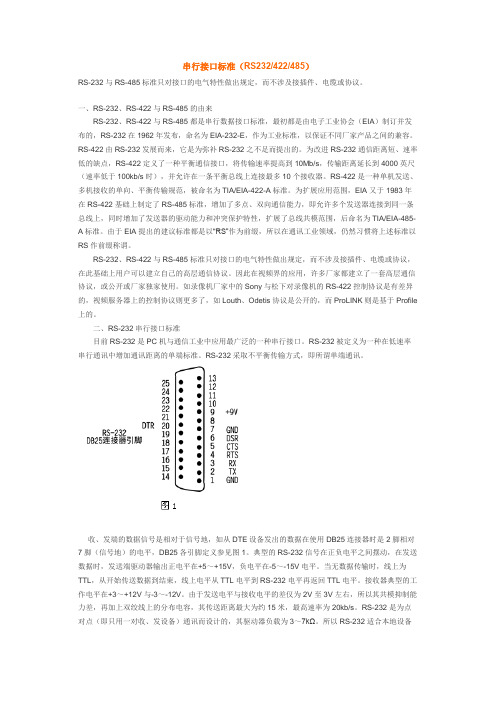
二、RS-232串行接口标准目前RS-232是PC机与通信工业中应用最广泛的一种串行接口。
RS-232被定义为一种在低速率串行通讯中增加通讯距离的单端标准。
串行通信接口及总线标准

RS-4
定义
RS-485是一种改进的串行 通信接口标准,由EIA制定。
特点
采用差分信号传输方式, 具有多站能力、高抗干扰 能力和长距离传输能力。
应用
广泛应用于工业自动化、 楼宇自动化和智能家居等 领域。
SPI
定义
应用
SPI是一种同步串行通信协议,由摩托 罗拉公司制定。
常用于微控制器和外围设备之间的通 信。
感谢观看
详细描述
在工业自动化控制系统中,各种设备如传感器、执行器、控制器等需要实时地进行数据交换和通信。 串行通信接口能够提供稳定、可靠的连接,使得设备间能够高效地传输数据,实现自动化控制和监测 。这有助于提高生产效率、降低成本、减少故障发生率。
智能家居系统
总结词
串行通信接口在智能家居系统中发挥关键作用,能够实现家庭设备的互联互通,提升家居生活的便利性和舒适度。
VS
详细描述
物联网设备间需要进行大量的数据交换和 通信,以实现设备的远程监控和管理。串 行通信接口能够提供高效、可靠的数据传 输服务,使得设备间能够稳定地进行通信 。这有助于促进物联网的发展和应用,提 高设备的可维护性和可管理性,降低运营 成本。
汽车电子系统
总结词
串行通信接口在汽车电子系统中具有重要价 值,能够实现汽车各系统间的信息共享和协 同工作,提高汽车的安全性和可靠性。
数据传输速率较慢。
03
02
特点
04
数据传输距离较远。
数据传输线少,成本低。
05
06
适用于不同设备之间的通信。
串行通信接口的重要性
01
02
03
04
实现设备之间的数据交换和通 信。
简化电路设计,降低成本。
通用串行通信接口标准(USB)

微计算机系统
微计算机系统
USB包的类型 包的类型
PACKET类型 Token Token Token Token Data Data Handshake Handshake Handshake Special PID名称 OUT IN SOF SETUP Data0 Data1 ACK NAK Stall PRE PID3 0 1 0 1 0 1 0 1 1 1 PID2 0 0 1 1 0 0 0 0 1 1 PID1 0 0 0 0 1 1 1 1 1 0 PID0 0 1 1 1 1 1 0 0 0 0
8BIT SYNC 8BIT PID
微计算机系统 6 USB的特点及应用 1.特点 USB计术的应用是计算机外设总线的重大变革。 USB有着很多优点: 1)用一种连接器类型连接多种外设。 USB对连接设备没有任何限制,仅提出了准则及带宽上界。USB统 一的4针插头取代了种类繁多的串、并插头,实现了将计算机常规 I/O设备,多媒体设备,通信设备以及家用电器统一为一种接口的愿 望。 2)用一个接口连接大量的外设 USB采用星形层次结构和HUB计术,允许一个USB主控机可连接多 达127个外设。两个外设间的距离可达5M,扩展灵活。 3)连接简单快捷 USB能自动识别USB系统中设备的接入或移走,真正做到即插即用; USB支持机箱外的热插拔连接,设备连接到USB时,不必打开机箱 或关电源。 4)总线提供电源 USB能提供5V,500mA的电源。 5)速度加快了 USB1.1版本有两种速度,高速(全速)为12MB/S,低速为1.5MB/S USB2.0 480MB/S
微计算机系统 B系统拓扑结构 USB协议定义了在USB系统中宿主Host与USB设备间的连接和通信, 其物理拓扑结构是星状的层层向上方式,也可看成一级与一级的级 连方式。允许最多连接127个设备,最上层是USB主控器。
otis rsl远程串行接口协议标准大全

Engineering CenterFive Farm SpringsFarmington, CT 06032Original Date: 2005-10-24 Document: SID00022 Project Number: C867 PC Number:Sheet 1 of 16Dwg / Part No:Remote Serial Link (RSL) Protocol Interface StandardDISTRIBUTION:Per notification document 53627.ORIGINAL APPROVAL:Prepared By:(Last, F I typed) (Signature and date) Approved By:(Last, F I typed) (Signature and date)Lerner, Bruce Bruce Lerner 2005-10-24 Leach, R. B. Bryan Leach 10/24/05Hoopes, Bruce Bruce Hoopes 2/15/06Vela, Haran Haran Vela 10/24/05 REVISION APPROVAL RECORD:Rev Date (yyyy-mm-dd) Project/PCRevised By:(Last, F I typed)Approved By:(Last, F I typed) (Signature and date)This work and the information it contains are the property of Otis Elevator Company (“Otis”). It is delivered to others on the express condition that it will be used only for, or on behalf of, Otis; that neither it nor the information it contains will be reproduced or disclosed, in whole or in part, without the prior written consent of Otis; and that on demand it and any copies will be promptly returned to Otis.Table of Contents1 Introduction (4)1.1 Purpose (4)1.2 Overview (4)1.3 Referenced Documents (4)2 RSL Overview (5)2.1 Communication Context (5)2.2 Otis RSL Protocol Mapping to the 7-layer ISO model (5)3 Otis RSL Functionality (6)4 OSI Layer 1: – RSL Physical (6)4.1 RSL Physical layer (6)4.1.1 Signal levels (6)4.1.2 Power levels (6)4.1.3 Bit Representation (6)4.1.4 Transmission Medium (6)4.1.5 Connectors (7)5 OSI Layer 2: – RSL Link (7)5.1 Frames (7)5.2 Data Cycles (Master Station driven) (8)5.2.1 Synchronization Cycle (8)5.2.2 Write Cycle (8)5.2.3 Read Cycle (8)5.3 Frame Timing (8)5.4 Error Detection (8)6 OSI Layers 3 – 6: Not Supported (9)7 OSI Layer 7 (9)7.1 Basic RSL Data format (9)7.1.1 Master Write /Slave Read (9)7.1.2 Master Read /Slave Write (9)7.2 CPI-11 / New Europa Line (NEL) RSL Data format (9)7.2.1 ELD Frames (9)7.2.2 7 & 16 Segment LCD Character Bit-maps (11)7.2.3 7 & 16 bit LCD Character Code list (12)7.2.4 ELD Frame Description (13)7.2.5 ELD Commands (14)7.3 Global Aesthetics RSL Data format (15)7.3.1 Frame 0 (15)7.3.2 Frame 1 (15)Appendix (16)APPENDIX A Definitions and Acronyms (16)1 Introduction1.1 PurposeThis document describes Otis’ application of the Remote Serial Link (RSL) within the Elevator system. This document should serve as a reference for creating modules that communicate using the RSL protocol. This document is meant to be referenced by multiple Module SIDs and does not intend to capture Module specific information.Any Module or Message specific information found in this document are examples and should not be construed as a definition of a standard for a Module or Message.This document will be updated when the RSL protocol standard or Otis’ application of RSL is amended, following approval by the Interface Change Control Board.1.2 OverviewThis document has been divided into the following sections and subsections. The combined information in these sections provides a complete description of Otis’ application of the RSL protocol.! Protocol Descriptiono The protocol description is an introduction to the Otis RSL Protocol and its expected functionality in relation to commercial protocol standards, primarily the 7-layer OSI standard.! Functional Allocationo This section specifies the functions that are supported by the interface. The functions in this section support or interact with functionality in other modules. The interface requirements aregenerally driven by the cross-module functional interactions.! Appendixo List of Acronyms and Definitions.o List of references that may be useful in understanding this document or its history.1.3 Referenced Documents[1] “System Architecture Interface Standard”, Otis Elevator Company, 2005. Document # SID00000.[2] “Signalling Subsystem Basic Data”, Flohr Ois Engineering, Otis Elevator Company, 8-September-1987.[3] Gewinner, J “Remote Station Family A9693 C1, C2, C3, C4 Basic Data”, Version 1.0, Flohr Otis,Berlin, 26-Feb-1988.[4] Shull, J “Industrial Control Unit Integrated Circuit Design Specification”, Revision 8, Otis ElevatorCompany, July 25, 1988.[5] Schulte, J “CPI11 ELD for OTIS2000 - Serial Protocol Definition”, Otis Elevator Company, Europeanand Transcontinental Operations, Berlin. Document # GAA25250B_BD1, 1994-03-03.[6] Drop, D “RSL Global Aesthetics Generic Fixtures Serial Protocol Description”, Otis ElevatorCompany, 2000-11-17, Document # 54723.2 RSL OverviewThis section describes the mapping of Otis’ application of RSL to the OSI model.This Remote Serial Link is a low-cost 4-wire bus that is intended for use in a single master – multiple slaves (I/O devices) configuration. Information is transferred as a continuous 64 frames of 5 bits each. The four wires applied by RSL between a master device and a slave device, are arranged as two pairs of wires, one providing communication, the other pair providing power. All stations on the RSL are connected in parallel. The RSL master provides synchronization for the read/write data transfer.The RSL is used as a long distance (hoistway length) communication channel for fixtures and bit-oriented inputs and outputs.2.1 Communication ContextRSL is being applied as one of the communication protocols in the elevator control system communication architecture. See reference [1].2.2 Otis RSL Protocol Mapping to the 7-layer ISO modelThis diagram maps the implemented layering for the RSL Protocol to the industry standard ISO 7-layer model.OSI Reference Model OSI-RMDefintionOtisLayersOtis Application Comm.Term7. Application Application-to-applicationcommunicationApplicationBit Mapping for: Basic RSL,CPI11/NEL and Global AestheticsProtocolData Unit(PDU)76. Presentation ConvertEncryptCompressPresentation65. Session EstablishManageTerminate54. Transport Error recover,Flow control Segment43. Network Determine path RouteN/APacket32. Link Media AccessControl,Framing errorLink RSL Frame21. Physical Transmit raw bitsPhysical RSL Bits13 Otis RSL FunctionalityThe Otis RSL protocol interface standard describes the mechanism for bit-oriented input and output betweenRSL slave stations and an RSL master station, and for bit-oriented output and commands/output between amaster and its slave devices. The RSL protocol addresses the physical and link layers, therefore they will be theonly layers described in this document.Typical use includes:• Bit-oriented input to the controller e.g. buttons, keyswitches• Bit-oriented output from the controller e.g. tell-tale lights• Position indicator data stream• Electro-luminescent Display (ELD) data4 OSI Layer 1: – RSL PhysicalFollowing a synchronization sequence, the master station transmits data for each slave station and then readsdata from the slave stations.4.1 RSL Physical layerThis section defines the signal levels, cabling and logical representation of signals for the RSL.4.1.1 Signal levelsParameter MinMaxUnit Signal voltage levels for L1 and L2 data lines -6.0 35.0 VdcCommon mode rejection voltage High level: VL1 >= VL2 + 0.8 Vdc Low level: VL1 <= VL2 + 0.3 Vdc +4.0Vdc4.1.2 Power levelsParameter MinMaxUnit Power lines 17.7 35.0 VdcVoltage drop on power distribution line 2.0 VdcCurrent - board specific4.1.3 Bit Representation4.1.3.1 Signal LevelsParameter MinMaxUnit Logical “0” -6.0 0.8 VdcLogical “1” 17.0 35.0 Vdc4.1.4 Transmission MediumThe four wire serial link consists of two data lines and two power lines. The system allows for a maximumserial line length of 300 m and a tap length of 2m.4.1.4.1 Data transmission linesThe data lines are twisted pair to minimize differential voltage distortion. L1 is the data line and L2 is the clockline used for synchronization.4.1.4.2 Power linesThe power line pair may be twisted or parallel. The transmission line should have end-to-end impedance ofapproximately 100 ohms and approximate capacitance of 60 pf/meter. See reference [2].4.1.5 Connectors4.1.5.1 “Slave” Platforms (e.g. fixtures)4.1.5.1.1 One row of 4 pinsThis connector supports two links, the link supplying power and the link supplying control messages.Post RSL Signal Name Signal DescriptionFunction1 DL1 Differential – signal forRSLData Line 1 2 DL2 Differential – signal forRSLData Line 23 ReturnVoltage return for fixture powerReturn power for FixtureElectronics4 V RS+33 Volt to power fixture Supply for Fixture Electronics power5 OSI Layer 2: – RSL LinkThe master station provides the basis for data transfer cycles. It provides the clock pulsed, drives the output for all frames (stations/addresses) during the write cycle and reads the inputs from all frames (slave stations/addresses) during the read cycle.5.1 FramesData is transferred in ‘frames’ that are a nominally defined time of 800 µS made up of a 100 µS clock pulse and 5 data bits of 100 µS each. The data bits are bounded by 100 µS ‘dead’ slots. See reference [3].5.2 Data Cycles (Master Station driven)Each data transfer cycle consists of a three sequential sub-cycles (from the master station perspective): write, read, synchronization. See reference [3].5.2.1 Synchronization CycleThe Synchronization Cycle consists of two frames without clock pulses that are inserted between everyL2L2data write/read cycle.5.2.2 Write Cycle5.2.3 Read Cycle5.3 Frame TimingSignal Min Typ Max Unit Cycle Time 788 800 835 µS Clock Width 80 100 146 µS Data 80 100 146 µS5.4 Error DetectionThe RSL protocol supports detection of loss of synchronization. The master station monitors for bit and clock pulse errors, providing a flag on the detected error. See reference [2].6 OSI Layers 3 – 6: Not Supported7 OSI Layer 7This section describes the application of the frames and sdata (PI) bits as applied for basic RSL, CPI11/NEL and Global Aesthetic fixtures.7.1 Basic RSL Data formatThe master station performs as described above (section 5). Each slave station/address) is responsible to read 5-bits from frame 0, the 5th bit from frames 4 – 39 (36 ‘sdata’ bits related to PI information) and the 5 bits associated with its address. See references [2] and [3].7.1.1 Master Write /Slave ReadFrame 0: master provides a command that is read by all slave stations Frames 1 – 3: Not usedFrames 4 – 63: Master provides data for 60 slave stations addressed 4 to 63, including 5th bit ‘sdata’for frames 4-39. Slave stations read 4 bits from their station time slot (address) and the 5th bit from frames 4-39.7.1.2 Master Read /Slave WriteMaster station reads all frames.L2L1L2L1Frame 64: stations with address 0 (for test purposes) respond in this frameFrames 65 – 67: Not usedFrames 68 – 127: slave stations with address 4-63 respond in their sequential frame (time slot)7.2 CPI-11 / New Europa Line (NEL) RSL Data formatThis format modifies the meaning of the sdata (5th data bit in each frame of frames 4-39) and is NOT compatible with PI devices using the basic RSL protocol. See reference [5].7.2.1 ELD Frames7.2.1.1 Frame 07.2.1.2 Frame 17.2.2 7 & 16 Segment LCD Character Bit-maps7.2.2.1 Segment locations for LCD Position Indicator7.2.2.2 Bit map for LCD Segment code7.2.3 7 & 16 bit LCD Character Code list7.2.4 ELD Frame Description7.2.5 ELD Commands7.3 Global Aesthetics RSL Data formatThis format modifies the meaning of the sdata (5th data bit in each frame of frames 4-39) extending the sdata fields through the 55th frame and is NOT compatible with PI devices using the basic RSL protocol but IS compatible with CPI11/NEL devices. See reference [6].7.3.1 Frame 056-1277.3.2 Frame 1AppendixAPPENDIX A Definitions and AcronymsCPI Car Position IndicatorELD Electro-luminescent DisplayISO International Standards OrganizationNEL New Europa LineIndicator PI PositionRSL RemoteLinkSerialDefinition SID StandardInterface串行通讯的基本概念:与外界的信息交换称为通讯。
西门子PLC几种常见的连接口和通讯协议

西门子PLC几种常见的连接口和通讯协议第一个大问题:RS232接口与RS485接口的区别一、接口的物理结构1、RS232接口:计算机通讯接口之一,通常 RS-232 接口以9个引脚 (DB-9) 或是25个引脚 (DB-25) 的型态出现,一般个人计算机上会有两组 RS-232 接口,分别称为 COM1 和 COM2。
2、RS485RS485无具体的物理形状,根据工程的实际情况而采用的接口。
二、接口的电子特性1、RS232:传输电平信号接口的信号电平值较高(信号“1”为“-3V至-15V”,信号“0”为“3至15V”),易损坏接口电路的芯片,又因为与TTL电平(0~“<0.8v”,1~“>2.0V”)不兼容故需使用电平转换电路方能与TTL电路连接。
另外抗干扰能力差。
2、RS485:传输差分信号逻辑“1”以两线间的电压差为+(2—6)V表示;逻辑“0”以两线间的电压差为-(2—6)V表示。
接口信号电平比RS-232降低了,就不易损坏接口电路的芯片,且该电平与TTL电平兼容,可方便与TTL电路连接。
三、通讯距离长短1、RS232:RS232传输距离有限,最大传输距离标准值为15米,且只能点对点通讯,最大传输速率最大为20kB/s。
2、RS485:RS485最大无线传输距离为1200米。
最大传输速率为10Mbps,在100Kb/S的传输速率下,才可以达到最大的通信距离。
采用阻抗匹配、低衰减的专用电缆可以达到1800米!超过1200米,可加中继器(最多8只),这样传输距离接近10Km。
四、能否支持多点通讯RS232:RS232接口在总线上只允许连接1个收发器,不能支持多站收发能力,所以只能点对点通信,不支持多点通讯。
RS485:RS485接口在总线上是允许连接多达128个收发器。
即具有多站通讯能力,这样用户可以利用单一的RS485接口方便地建立起设备网络。
五、通讯线的差别RS232:可以采用三芯双绞线、三芯屏蔽线等。
otis通信协议
OTIS通信协议
RSL由主控板(LCB_II)和最多60个RS节点(也就是RS5,RS18等电路板)组成。
两个链接(轿厢和厅站链)都必须由终端板(LT1)端接。
每个RS节点支持4对独立的输入/输出点E1~E8),另外还可以连接一个位置(层楼)指示器(E9~E11)。
RSL可以通过服务工具在LCBII的EEPROM中配置。
RSL串行总线由时钟和数据线(L1 ,L2 )和电源线组成(30VDC,接地)。
)
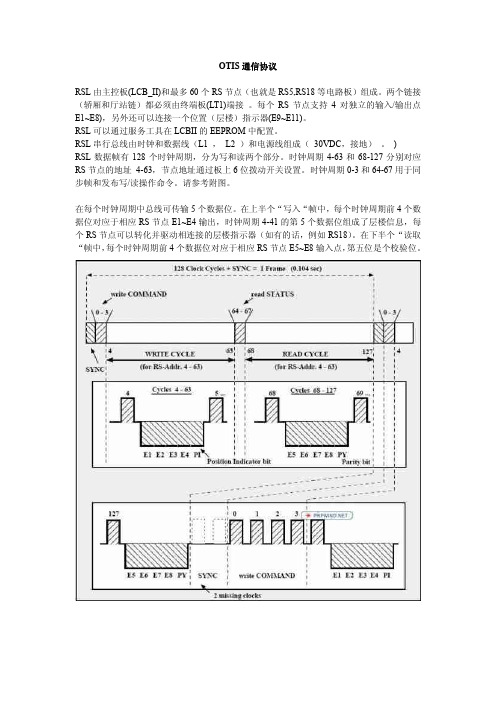
RSL数据帧有128个时钟周期,分为写和读两个部分。
时钟周期4-63和68-127分别对应RS节点的地址4-63,节点地址通过板上6位拨动开关设置。
时钟周期0-3和64-67用于同步帧和发布写/读操作命令。
请参考附图。
在每个时钟周期中总线可传输5个数据位。
在上半个“写入“帧中,每个时钟周期前4个数据位对应于相应RS节点E1~E4输出,时钟周期4-41的第5个数据位组成了层楼信息,每个RS节点可以转化并驱动相连接的层楼指示器(如有的话,例如RS18)。
在下半个“读取“帧中,每个时钟周期前4个数据位对应于相应RS节点E5~E8输入点,第五位是个校验位。
奥迪斯技术资料英文缩写说明
4. MONITOR-----监控 TEST-----测试 SETUP-----设置
5.STS-C----单台电梯状态 STS-1-------两台电梯状态 GROUP------多台电梯状态
6.电梯的运行模式: NOR---正常运行模式
IDL---空载无人呼梯模式
就是我们平常所说的TT
3. OCSS—OPERATIONAL CONIROL SUBSYSTEM 操作控制子系统
MCSS—MOTION COMMAND SUBSYSTEM 运行指令子系统
DCSS(DISS)—DOOR CONIROL SUBSYSTEM 门控制子系统
DBSS—DRIVE AND CONIROL SUBSYSTEM 驱动及制动子系统
1.RSL-----Remote Serial Link
远程的 连续的 连接
一般指电梯控制板上的远程连接端口,也就是我们平时说的串口线(24V+,0V,时钟,数据)
如LCBII上的P9(轿厢连接端口)和P10(大厅连接端口).
2.Service tool 服务器
7.COP---Car Operational Panel 轿厢操作盘
8.BUZ--蜂鸣器
9.CPI--轿厢位置指示(轿内显示)
10.HPI--厅显
11.osl--轿
几种串行通信接口标准
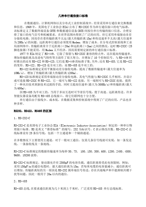
几种串行通信接口标准在数据通信、计算机网络以及分布式工业控制系统中,经常采用串行通信来交换数据和信息。
1969年,美国电子工业协会(EIA)公布了RS-232C作为串行通信接口的电气标准,该标准定义了数据终端设备(DTE)和数据通信设备(DCE)间按位串行传输的接口信息,合理安排了接口的电气信号和机械要求,在世界范围内得到了广泛的应用。
但它采用单端驱动非差分接收电路,因而存在着传输距离不太远(最大传输距离15m)和传送速率不太高(最大位速率为20Kb/s)的问题。
远距离串行通信必须使用Modem,增加了成本。
在分布式控制系统和工业局部网络中,传输距离常介于近距离(<20m)和远距离(>2km)之间的情况,这时RS-232C(25脚连接器)不能采用,用Modem又不经济,因而需要制定新的串行通信接口标准。
1977年EIA制定了RS-449。
它除了保留与RS-232C兼容的特点外,还在提高传输速率,增加传输距离及改进电气特性等方面作了很大努力,并增加了10个控制信号。
与RS-449同时推出的还有RS-422和RS-423,它们是RS-449的标准子集。
另外,还有RS-485,它是RS-422的变形。
RS-422、RS-423是全双工的,而RS-485是半双工的。
RS-422标准规定采用平衡驱动差分接收电路,提高了数据传输速率(最大位速率为10Mb/s),增加了传输距离(最大传输距离1200m)。
RS-423标准规定采用单端驱动差分接收电路,其电气性能与RS-232C几乎相同,并设计成可连接RS-232C和RS-422。
它一端可与RS-422连接,另一端则可与RS-232C连接,提供了一种从旧技术到新技术过渡的手段。
同时又提高位速率(最大为300Kb/s)和传输距离(最大为600m)。
因RS-485为半双工的,当用于多站互连时可节省信号线,便于高速、远距离传送。
许多智能仪器设备均配有RS-485总线接口,将它们联网也十分方便。
- 1、下载文档前请自行甄别文档内容的完整性,平台不提供额外的编辑、内容补充、找答案等附加服务。
- 2、"仅部分预览"的文档,不可在线预览部分如存在完整性等问题,可反馈申请退款(可完整预览的文档不适用该条件!)。
- 3、如文档侵犯您的权益,请联系客服反馈,我们会尽快为您处理(人工客服工作时间:9:00-18:30)。
Remote Serial Link (RSL) Protocol Interface Standard
DISTRIBUTION: Per notification document 53627.
ORIGINAL APPROVAL:
Prepared By:
(Last, F I typed) (Signature and date)
7.1 Basic RSL Data format ................................................................................................... 9
7.1.1 Master Write /Slave Read ..................................................................................................................... 9 7.1.2 Master Read /Slave Write ..................................................................................................................... 9
5.3 Frame Timing.................................................................................................................. 8 5.4 Error Detection................................................................................................................ 8
5.2.1 Synchronization Cycle.......................................................................................................................... 8 5.2.2 Write Cycle........................................................................................................................................... 8 5.2.3 Read Cycle............................................................................................................................................ 8
3 Otis RSL Functionality................................................................................... 6 4 OSI Layer 1: – RSL Physical ......................................................................... 6
6 OSI Layers 3 – 6: Not Supported .................................................................. 9 7 OSI Layer 7...................................................................................................... 9
Form PA1021 Rev. 2002-06-11
Unpublished Work - Copyright © Otis Elevator Company
Page: 2 of 15
Document: SID00022
Table of Contents
1 Introduction..................................................................................................... 4
4.1 RSL Physical layer.......................................................................................................... 6
4.1.1 Signal levels.......................................................................................................................................... 6 4.1.2 Power levels.......................................................................................................................................... 6 4.1.3 Bit Representation ................................................................................................................................ 6 4.1.4 Transmission Medium .......................................................................................................................... 6 4.1.5 Connectors ............................................................................................................................................ 7
Lerner, Bruce来自Bruce Lerner 2005-10-24
Approved By: (Last, F I typed)
Leach, R. B.
Hoopes, Bruce Vela, Haran
(Signature and date)
Bryan Leach 10/24/05
Bruce Hoopes 2/15/06 Haran Vela 10/24/05
2 RSL Overview ................................................................................................. 5
2.1 Communication Context ................................................................................................. 5 2.2 Otis RSL Protocol Mapping to the 7-layer ISO model................................................... 5
7.2 CPI-11 / New Europa Line (NEL) RSL Data format ..................................................... 9
REVISION APPROVAL RECORD:
Rev Date (yyyy-mm-dd)
Project/ Revised By: PC (Last, F I typed)
Approved By: (Last, F I typed)
(Signature and date)
Description of Change Reason for Change
1.1 Purpose............................................................................................................................ 4 1.2 Overview......................................................................................................................... 4 1.3 Referenced Documents ................................................................................................... 4
Engineering Center Five Farm Springs Farmington, CT 06032
Original Date: 2005-10-24 Project Number: C867 Dwg / Part No: