滚珠丝杠设计说明书
滚珠丝杠设计说明说
滚珠丝杠设计说明说滚珠丝杠是一种常用于传递旋转运动和直线运动的机械元件,它通常由螺母、螺杆和滚珠组成。
滚珠丝杠具有高效率、高刚度、高精度、长寿命等优点,广泛应用于工程机械、航空航天、机床等领域。
1.长度选择:滚珠丝杠的长度应根据具体应用场景来确定。
较长的丝杠可以提供较大的行程,但也会增加自振频率和扭转刚度,影响系统的稳定性。
因此,在设计过程中需要综合考虑行程需求和系统稳定性。
2.直径选择:滚珠丝杠的直径决定了其负载能力,直径越大,负载能力越高。
选择直径时需要考虑负载情况和运动速度。
通常,通过计算负载系数和速度系数,可以确定滚珠丝杠的合适直径。
3.螺距选择:螺距是滚珠丝杠的重要参数,它决定了滚珠在一个螺旋周期内所传递的行程。
螺距越大,速度越快,但力矩也会增加。
在选择螺距时,需要综合考虑负载和速度要求。
4.滚珠选择:滚珠的选择直接影响滚珠丝杠的负载能力和精度。
一般来说,滚珠越大,负载能力越高,但精度可能降低;滚珠越小,精度越高,但负载能力降低。
根据具体应用要求,选择适当大小的滚珠。
5.轴承支撑方式:滚珠丝杠需要在两端通过轴承来支撑。
轴承的选择要考虑运动速度、负载和刚度等要求。
一般情况下,可以采用角接触球轴承或推力球轴承来支撑。
6.润滑方式:滚珠丝杠在工作时需要进行润滑以减小摩擦和磨损。
常见的润滑方式有油脂润滑和油润滑。
油脂润滑可以提供良好的密封性和冷却效果,适用于低速轴承;而油润滑适用于高速操作,可以提供更好的冷却和泄漏控制。
7.驱动方式:滚珠丝杠的驱动方式可以采用电动、液压或气动。
电动驱动是最常见和广泛应用的方式,它能够提供精确控制和较高的驱动效率。
液压和气动驱动方式适用于承载大负载和长行程的应用。
滚珠丝杠的设计需要根据具体应用需求来选择合适的参数和材料。
设计人员需要结合机械原理、材料力学、热力学等知识,进行系统分析和计算,确保滚珠丝杠能够满足设计要求,提供可靠的运动传递和精确的位置控制。
此外,在设计过程中还需要考虑制造成本、安装要求和维护方便等因素,并与其他机械元件进行协调和配合,以实现整体设计的一致性和优化。
机械系统设计 (滚珠丝杠)PPT课件

2 机械系统设计--机械传动装置滚珠丝杠副
双推—自由
1.轴向刚度低,与螺母位置有关; 2.双推端可预拉伸安装; 3.适宜中小载荷与低速,更适宜垂直安装,短丝杠。
固定可以用深沟球轴承和双向推力轴承组合或用圆锥滚子轴承
2 机械系统设计--机械传动装置滚珠丝杠副
(2) 轴承的组合安装支承示例
2 机械系统设计--机械传动装置滚珠丝杠副
2 机械系统设计--机械传动装置滚珠丝杠副
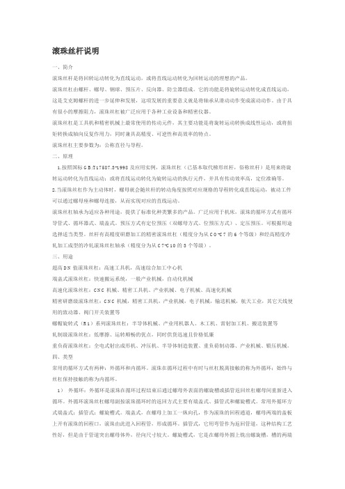
滚珠丝杠副的特点
传动效率高 运动平稳 工作寿命长 定位精度和重复定位精度高 同步性好 可靠性高 不能自锁 制造工艺复杂
2 机械系统设计--机械传动装置滚珠丝杠副
滚珠丝杠副的典型结构类型
从螺纹滚道的截面形状、滚珠的循环方式和消除轴 向间隙的调整方法进行区别。
1,产生的轴向位移(即间隙)为:
1 (
Z1
1 )np
Z2
其中:n为螺母同方向转过的齿数
p为丝杠的导程
例:若Z1=99,Z2=100,n=1, p=6mm 则d=0.6μm
2 机械系统设计--机械传动装置滚珠丝杠副
(3) 垫片调隙式
调整垫片厚度,使螺母产生轴向位移,该形式结构简单,调整较为 方便,应用广,但仅适用于一般精度机构。
滚珠丝杠在工作负载fn和转矩tnm共同作用下引起每个导程的变形量esie38001038机械系统设计机械传动装置滚珠丝杠副按最不利的情况即取ffm则丝杠在工作长度上的弹性变形所引起的导程误差为通常要求丝杠的导程误差应小于其传动精度的12即edpfgjeapf1075216045910206143800101310107521503机械系统设计机械传动装置滚珠丝杠副试设计一数控机床工作台进给用滚珠丝杠副
1.轴向刚度最高; 2.预拉伸安装时,须加载荷较小,轴承寿命较高 3.适宜高速、高刚度、高精度。
项目3数控车床滚珠丝杠副设计
• 滚珠丝杠,滚珠丝杠的螺母带动滑块和工作台在导轨上运动,以完成 工作台在X, Y方向的直线运动。导轨副、滚珠丝杠螺母副和伺服电动 机等均已标准化,由专门厂家生产,设计时只需根据工作载荷选取即 可。
项目三数控车床滚珠丝杠副设计
• 3. 1滚珠丝杠副 • 3. 2滚珠丝杠副间隙调整及安装 • 3. 3滚珠丝杠副设计案例导入 • 3. 4数控车床滚珠丝杠副设计
返回
3. 1滚珠丝杠副
• 常见的机械传动部件有螺旋传动、齿轮传动、同步带传动、高速带传 动和各种非线性传动部件等。其中螺旋传动机构也称为丝杠螺母机构, 它主要是用于将旋转运动变换为直线运动或将直线运动变换为旋转运 动的。丝杠螺母机构有滑动摩擦机构和滚动摩擦机构之分,滑动丝杠 结构简单、加工方便、成本低、传动效率低,而滚动丝杠结构复杂、 加工难、成本高、传动效率高(92%一98 % )。因此,后者在机电一 体化系统中得到广泛应用。
下一页 返回
3. 1滚珠丝杠副
• (2)丝杠传动、螺母移动,如图3一1 (b)所示。该传动形式需要限制螺 母的移动,故需要导向装置。其特点是结构紧凑、丝杠刚性较好,适 用于工作行程较大的场合。
• (3)螺母传动、丝杠移动,如图3一1 (c)所示。该传动形式需要限制螺 母传动和丝杠移动,由于结构较复杂且占用轴向空间较大,故应用较 少)。
上一页 下一页 返回
3. 1滚珠丝杠副
• 3.1.3滚珠丝杠副主要尺寸参数
• 滚珠丝杠副主要尺寸参数有:公称直径Do,丝杠小径d,,丝杠大径d, 螺母小径D1,螺母大径D,滚珠直径db,基本导程(或螺距)P,滚珠工 作圈数及滚珠数,具体如图3 -6所示。
滚珠丝杠设计说明书
广西科技大学机制工艺课程设计(滚珠丝杠)设计说明书学生姓名:刘淮学生学号:20150140702指导教师:唐满专业班级:机械Z135班专业方向:广西科技大学职业技术教育学院二零一六年六月机械制造工艺学课程设计任务书一、设计题目滚珠丝杠的预拉伸结构二、原始资料(1) 滚珠丝杠外径40mm,导程10(2) 双螺母预紧三、上交材料1.CAD制零件图 3张2、设计说明书一份 1套滚珠丝杠预拉伸结构说明书一、用途:该滚珠丝杠可用于车床、铣床等数控铣床使用,定位精度高,制造等级高。
二、重要数据1、规格:滚珠丝杠外径为40mm,导程为10,总长为1407,有效行程为1100mm。
制造材料为45钢,制造等级为研磨级,有较高的接触精度。
2、循环方式:采用弯管是外循环,采用3.5圈X1有效循环圈数,该方式装配简单,使用面广。
3、螺母选用:采用双螺母,法兰盘式连接,方便预紧,预紧方式采用垫片式可调预紧。
螺母内径为65mm,内径为40mm,螺母及法兰盘总长152mm。
4、支撑方式:电机端固定和另一端铰支撑,采用铰接触轴承支撑,轴承型号为7206C,接触为60度,有较好的稳定性,能做到有效支撑。
5、电机连接方式:采用联轴器电机直连方式。
这种连接方式不但方片轻巧,不但能提高传动效率,而且能减少磨损,减少装配所需空间。
6、联轴器的选用:采用最先进的弹性膜片联轴器,冲击载荷小,是现在普遍再用电机直连的一种方式。
7、轴端螺母的选用:采用M30 B级螺母,制造材料为45钢。
三、转配的选用:根据丝杠的材料和外径,导程,选用合理的丝杠形成,达到最佳的配合。
丝杠机械加工工艺设计说明书
第 1 章 零件的分析
1. 1.1 零件的作用
丝杠是一种精度很高的零件,它能精确地确定工作台坐标位置,将旋转运动 转换成直线运动,面且还要传递一定的动力,所以在精度、强度及耐磨性等方面 都有很高的要求。所以,丝杠的加工从毛坯到成品的每道工序都要周密考虑,以 提高其加工精度。
1.2 零件的结构简介 1.2.1 丝杠的分类
2.3 制订工艺路线
材料 精度等级 工艺过程 9Mn2V 6级 工序内容 1.锻造 2.球化退火 3.车端面打中心孔 4.粗车外圆 5.高温时效 5.牢外圆打中心孔 7.半精车外圆 8.粗磨外圆 9.淬火(t=800℃),中温回 火(t=260℃) 14.研磨两顶尖孔 11.粗磨外圆 12.粗磨出螺纹槽 13.人工时效(t=260℃) 双顶尖孔 双顶尖孔 外圆表面 双顶尖孔 双顶尖孔 外圆表面 双顶尖孔 定位基准
2.1 确定毛坯材料
丝杠材料的选择是保证丝杠质量的关键,一般要求是: (1) 具有优良的加工性能,磨削时不易产生裂纹,能得到良好的表面光洁
度和较小的残余内应力,对刀具磨损作用较小。 (2) 抗拉极限强度一般不低于 588MPa。 (3) 有良好的热处理工艺性,淬透性好,不易淬裂,组织均匀,热处理变形 小,能获得较高的硬度,从而保证丝杠的耐磨性和尺寸的稳定性。 (4) 材料硬度均匀,金相组织符合标准。常用的材料有:不淬硬丝杠常用 T10A, T12A 及 45 等;淬硬丝杠常选用 9Mn2V,CrWMn 等。其中 9Mn2V 有较 好的工艺性和稳定性,但淬透性差,常用于直径≤50mm 的精密丝杠;CrWMn 钢 的优点是热处理后变形小,适用于制作高精度零件,但其容易开裂,磨削工艺性 差。 丝杠的硬度越高越耐磨,但制造时不易磨削。 丝杠材料要有足够的强度, 以保证传递一定的动力;应具有良好的热处理工 艺性(淬透性好、热处理变形小、不易产生裂纹),并能获得较高的硬度、良好的 耐磨性。丝杠螺母材料一般采用 GCrl5、CrWMn、9CrSi、9Mn2V,热处理硬度 为 60~62HRC。整体淬火在热处理和磨削过程中变形较大,工艺性差,应尽可能
滚珠丝杆说明
滚珠丝杆说明一、简介滚珠丝杆是将回转运动转化为直线运动,或将直线运动转化为回转运动的理想的产品。
滚珠丝杠由螺杆、螺母、钢球、预压片、反向器、防尘器组成。
它的功能是将旋转运动转化成直线运动,这是艾克姆螺杆的进一步延伸和发展,这项发展的重要意义就是将轴承从滑动动作变成滚动动作。
由于具有很小的摩擦阻力,滚珠丝杠被广泛应用于各种工业设备和精密仪器。
滚珠丝杠是工具机和精密机械上最常使用的传动元件,其主要功能是将旋转运动转换成线性运动,或将扭矩转换成轴向反复作用力,同时兼具高精度、可逆性和高效率的特点。
滚珠丝杠主要参数为:公称直径与导程。
二、原理1.按照国标GB/T17587.3-1998及应用实例,滚珠丝杠(已基本取代梯形丝杆,俗称丝杆)是用来将旋转运动转化为直线运动;或将直线运动转化为旋转运动的执行元件,并具有传动效率高,定位准确等。
2.当滚珠丝杠作为主动体时,螺母就会随丝杆的转动角度按照对应规格的导程转化成直线运动,被动工件可以通过螺母座和螺母连接,从而实现对应的直线运动。
滚珠丝杠轴承为适应各种用途,提供了标准化种类繁多的产品。
广泛应用于机床,滚珠的循环方式有循环导管式、循环器式、端盖式。
预压方式有定位预压(双螺母方式、位预压方式)、定压预压。
可根据用途选择适当类型。
丝杆有高精度研磨加工的精密滚珠丝杠(精度分为从CO-C7的6个等级)和经高精度冷轧加工成型的冷轧滚珠丝杠轴承(精度分为从C7-C10的3个等级)。
三、用途超高DN值滚珠丝杠:高速工具机,高速综合加工中心机端盖式滚珠丝杠:快速搬运系统,一般产业机械,自动化机械高速化滚珠丝杠:CNC机械、精密工具机、产业机械、电子机械、高速化机械精密研磨级滚珠丝杠:CNC机械,精密工具机,产业机械,电子机械,输送机械,航天工业,其它天线使用的致动器、阀门开关装置等螺帽旋转式(R1)系列滚珠丝杠:半导体机械、产业用机器人、木工机、雷射加工机、搬送装置等轧制级滚珠丝杠:低摩擦、运转顺畅的优点,同时供货迅速且价格低廉重负荷滚珠丝杠:全电式射出成形机、冲压机、半导体制造装置、重负荷制动器、产业机械、锻压机械。
滚珠丝杠技术说明
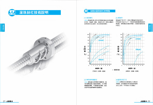
八 八滾珠絲杠的特點
(”高信賴性
(之) 高效率
八88八滾珠絲杠是以多年來所累積的製品技術為基礎, 滾珠絲杠下圖 所示 ,具有比滑動絲杠更高的效率 ,
從材料 、熱處理 、製造 、檢査至出貨 ,都是以嚴謹的 所需扭矩只有30 ^ 以下 。可輕易將直線運動變換為回
品保制度來加以管理 ,因此具有高信賴性 。
1.19
6.6
14.76
1.0
3.05
2.3 滾 珠 螺 桿 幾 何 公 差 的 標 示
滾珠螺桿的安裝部位之精度 ,其必要項目如下 :
〔1〕相對於螺紋溝面的軸線八 ,測定螺桿支持部位的半徑方向圓偏擺値。
滚
〔2〕相對於螺桿支持部位的軸線卩 ,測定零件安裝部位的同軸度。
珠 絲
〔3〕相對於螺桿軸支持部位的軸線〖,測定支持部位的端面的直角度。
4
6 土25^ 土30先土35知土45光土38兄土38先土45光 土50先 ― ―
6
10 土20呢士25^ 土30先土35知土30知土30知土35^ 士躺 ― 土 躺 土45知
10 25 土15先土20^ 土25^ 土30拓土25^ 土25^ 土30先 土35兒 ― 土35^ 土40兄
⑴⑴丈 :⑴⑴) 0.015 0.025 0.05
0 门七 卬⑴ 研磨級螺桿最大軸向間隙
⑴门4 :⑴⑴) 0
招格
1404-4 1604-3 1604-4 1605-3 1605-4 1610-3 2005-4 2504-4 2505-4 2510-3 2510-4 3205-4 3206-4 3210-3 3210-4 4005-4 4006-4 4010-3 4010-4 5010-3 5010-4 6310-4 6320-3 8010-4 8020-3
汤姆森直线产品球丝杆、滚珠丝杆和滚珠丝杠说明书
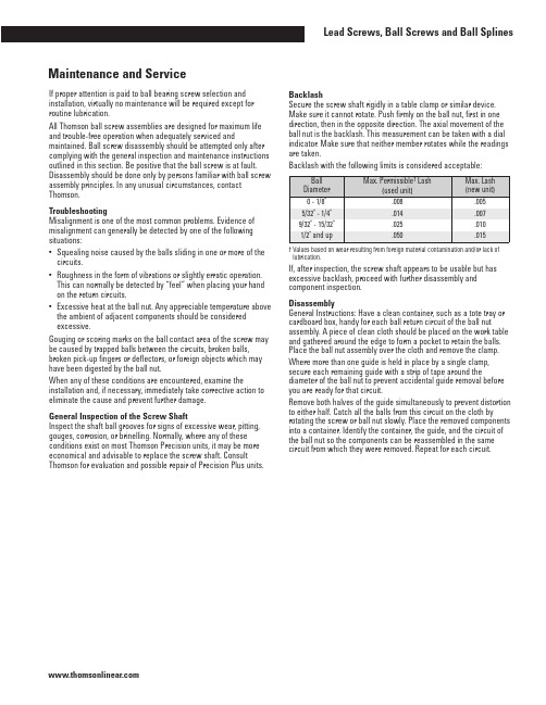
If proper attention is paid to ball bearing screw selection and installation, virtually no maintenance will be required except for routine lubrication.All Thomson ball screw assemblies are designed for maximum life and trouble-free operation when adequately serviced and maintained. Ball screw disassembly should be attempted only after complying with the general inspection and maintenance instructions outlined in this section. Be positive that the ball screw is at fault. Disassembly should be done only by persons familiar with ball screw assembly principles. In any unusual circumstances, contact Thomson.TroubleshootingMisalignment is one of the most common problems. Evidence of misalignment can generally be detected by one of the following situations:•Squealing noise caused by the balls sliding in one or more of the circuits.•Roughness in the form of vibrations or slightly erratic operation. This can normally be detected by “feel” when placing your hand on the return circuits.•Excessive heat at the ball nut. Any appreciable temperature above the ambient of adjacent components should be considered excessive.Gouging or scoring marks on the ball contact area of the screw may be caused by trapped balls between the circuits, broken balls, broken pick-up fingers or deflectors, or foreign objects which may have been digested by the ball nut.When any of these conditions are encountered, examine the installation and, if necessary, immediately take corrective action to eliminate the cause and prevent further damage.General Inspection of the Screw ShaftInspect the shaft ball grooves for signs of excessive wear, pitting, gouges, corrosion, or brinelling. Normally, where any of these conditions exist on most Thomson Precision units, it may be more economical and advisable to replace the screw shaft. Consult Thomson for evaluation and possible repair of Precision Plus units.BacklashSecure the screw shaft rigidly in a table clamp or similar device. Make sure it cannot rotate. Push firmly on the ball nut, first in one direction, then in the opposite direction. The axial movement of the ball nut is the backlash. This measurement can be taken with a dial indicator. Make sure that neither member rotates while the readings are taken.Backlash with the following limits is considered acceptable:† Values based on wear resulting from foreign material contamination and/or lack of lubrication.If, after inspection, the screw shaft appears to be usable but has excessive backlash, proceed with further disassembly and component inspection.DisassemblyGeneral Instructions: Have a clean container, such as a tote tray or cardboard box, handy for each ball return circuit of the ball nut assembly. A piece of clean cloth should be placed on the work table and gathered around the edge to form a pocket to retain the balls. Place the ball nut assembly over the cloth and remove the clamp. Where more than one guide is held in place by a single clamp, secure each remaining guide with a strip of tape around the diameter of the ball nut to prevent accidental guide removal before you are ready for that circuit.Remove both halves of the guide simultaneously to prevent distortion to either half. Catch all the balls from this circuit on the cloth by rotating the screw or ball nut slowly. Place the removed components into a container. Identify the container, the guide, and the circuit of the ball nut so the components can be reassembled in the same circuit from which they were removed. Repeat for each circuit.General Description Array A Thomson ball screw is a force and motion transfer device belonging to the family of power transmission screws. It replaces sliding friction of the conventional power screw with the rolling friction of bearing balls. The balls circulate in hardened steel races formed by concave helical grooves in the screw and nut. All reactive loads between the screw and nut are carried by the balls which provide the only physical contact between these members.As the screw and the nut rotate relative to each other, the balls are diverted from one end and carried by ball guides to the opposite end of the nut. This recirculation permits unrestricted travel of the nut in relation to the screw.Method I:Ball nuts using a deflector return system are identified by threaded deflector studs extending through holes in the nut and the guide clamp. Lock nuts on the deflector studs are used to secure the clamps that hold the guides in place.Method II:Ball nuts with pick-up fingers are identified by the finger projections integral with the guide. In this method, capscrew fasteners are used to fasten the clamp that holds the guide in place. Pick-up Finger Method:Refer to the Component Inspection section. Deflector Method:To remove the deflectors from the ball nut assembly, remove the ball nut from the screw shaft. The ball nut must be rotated since the deflectors engage loosely in the screw ball grooves and act as a thread. The deflectors now can be removed from the opposite ends of the ball nut so that you can use them forreference during component inspection.Component Inspection and ReplacementBalls: If there is more than one circuit in the ball nut, count the balls in each of the separate containers to be sure each has the same number (within a variation of three balls). Check random samples (about 1/4 of the balls for a circuit) for the following:•True roundness, with a .0001 in. maximum variation.•Signs of scuffing or fish scaling.•More than .0001 in. diameter variation between balls of the same circuit.Where the random sampling shows balls out of round, signs of scuffing or variation of diameter in excess of .0001 in., or short count in any circuit, all balls in the unit must be replaced with a complete set of new balls. Ball kits are available from Thomson.To ensure proper operation and long life of the serviced assembly, it is imperative that the diameters of all the replacement balls do not vary in excess of .00005 in. If Thomson kits are not used for service, make sure the balls meet the above specification. (Note: Use only chrome alloy steel balls, Grade 25 or better. Carburized balls or carbon steel balls will not provide adequate life.) See Ball Chart table.Deflectors:Examine the ends of the deflectors for wear or brinelling. Wear can be determined by comparison with the unused ends of the two outside deflectors. Since these ends have not been subjected to wear from balls, they are in a like-new condition. Where wear or brinelling is evident, it is best to replace the deflectors with new ones. Pick-up Fingers: Inspect the pick-up fingers, which consist of short extensions at the end of the guides. Replace with new guides if a ball brinell impression appears on the tip. Remove any burrs on the fingers. If the guides were distorted during removal, replace with new guides. Ball Nut:Inspect the internal threads of the ball nut for signs of excessive wear, pitting, gouges, corrosion, spalling, or brinelling in the ball groove area. On large ball nuts, running the tip of your finger along the groove which is accessible will enable you to detect a secondary ridge in the ball groove area when wear is excessive or brinelling has occurred. (The extended lead of a mechanical pencil can also be used as a groove probe.) If inspection indicates any of these flaws, the ball nut assembly should be replaced.Wipers:Prolonged use and environmental conditions will generally determine the condition of wipers. After cleaning wipers, reassemble over the screw shaft to determine whether a snug fit is maintained over the complete contour of the screw shaft. Any loose fitting or worn wipers should be replaced. Wiper kits are available for Thomson ball screws.Note: If the assemblies have had extended use, it is recommended that all low cost items be replaced with new parts (i.e., balls, guides, deflectors, clamps). These can be ordered by simply referring to the assembly part number purchased.ReassemblyCleaning: Clean all components with a commercial solvent and dry thoroughly before reassembly.Deflector Method: Where the ball nut is equipped with deflectors, install these and secure temporarily by running the lock nuts down the studs and tightening.General Instructions: Position the ball nut on the screw shaft. Ball nuts with deflectors have to be screwed on. Other ball nuts will slide on. Using dowels with an O.D. approximately equal to the diameter of the balls, center the ball nut grooves with the shaft grooves by inserting dowels into each of the ball nut return circuit holes.Remove the second dowel from one end. With the ball return holes up, fill the circuit with balls from the container corresponding to that circuit. Turning the screw in the ball nut will help to feed the balls into the groove. When the circuit is full, the balls will begin to lift the end dowel from its position. To be sure there are no voids, lightly tap the top bearing ball and see if the end dowel moves.The remaining ball in the container should fit into one of the halves of the return guide with space for about three to six left.Note: There must be some free space in the ball circuit so the balls will roll and not skid. Do not try to add extra balls into the circuit. Place a dab of bearing grease at each end of the half return guide to hold the balls in place. Now, take the other half of the return guide and place it over the half guide you have filled with balls and insert two ends of the ball guide into the respective hole in the ball nut. Seat by tapping gently with a rawhide or plastic mallet.Note: Where more than one ball circuit must be filled in the ball nut, tape the ball return circuit to the ball nut to prevent accidental removal. Repeat the filling procedure for the remaining circuits. With all ball circuits filled and all return guides in place, secure the return guides with the retaining clamp.CAUTION: Care should be taken to ensure that balls are not accidentally trapped between circuits in units having pick-up fingers. In deflector units, the deflectors will fill this space.Inspection: Wrap tape around the ball grooves at the ends of the screw shaft to prevent the ball nut from rolling off. Now inspect the assembly for free movement of the ball nut along the entire stroke. There should be no binding, squeal, or roughness at any point. Reducing Backlash: Backlash can be reduced by replacing all the balls with a larger size. If the diameters of the bearing balls are increased by .001 in., backlash is decreased by .003 in. (Ball kits are available for these applications.)Ball Chart (Grade 25 or Better)240Inspection and Existing Preload Check: Whenever possible, the complete ball screw assembly should be removed from the machine prior to a thorough inspection. Preliminary screw inspection can be made while the unit is still in the machine. Preload can be determined by measuring movement of the nut in respect to the screw shaft. Clamp an indicator to the screw shaft with its probe resting on the face of the nut. Apply a load to the machine carriage in both directions. Be sure that the screw cannot rotate or move axially. Any measurable backlash between the ball nut and screw is an indication that preload does not exist. (See Figure 18.)If no backlash exists, proceed further as outlined to determine whether proper preload remains in the unit. Existing preload, Wp, can be determined by measuring torque, Tp, using the following formula: Wp =Tp.007where:Wp = Preload force, in lb.Tp = Torque, in lb-in. (due to preload only) Note: The above check is to determine preload only, and does not take into account torque due to seal drag or operating load.Torque can be measured by means of a spring scale mounted to any projection on the ball nut or by means of a lever or rod secured to the ball nut. In taking this measurement, be sure the exact lever arm distance is measured. (See Figure 18.) This measurement (inch) multiplied by the scale reading (lb.) equals Tp (torque lb-in.). Existing preload can now be determined using the above formula.Preload adjustment of a Precision ball screw (Figure 18) requires no disassembly. Possible removal of the ball nut from the machine housing may be necessary to expose the adjusting nut. Disassembly: If in doubt about disassembly of preloaded ball nuts, contact Thomson Application Engineering. If the unit is to be disassembled for general repair, follow the steps previously outlined in this section.If being disassembled for preload adjustment, follow the guidelines except remove only one-half of the ball nut assembly to an arbor. If a standard arbor is not available, one can be made from a piece of shafting or tubing with a diameter approximately .005 inch less than the root diameter of the ball grooves in the screw shaft. Both halves of the ball nut will come apart as soon as the last ball in the nut is free of the grooves in the screw shaft. It is not necessary to remove the other half from the screw.Preload Adjustment: The adjusting nut unit in Figure 18 can be adjusted to the desired preload with the use of additional shims. To make further adjustment, loosen the set screw lock located on the periphery of the lock nut. Use a spanner wrench to rotate the adjusting nut to the desired setting. Recheck the preload.For all other standard units in Figure 18, a shim increase of .001 inch will, as a general rule, increase preload by 500 to 1,000 lb. This varies depending upon screw size; therefore, some judgement and trial and error may be necessary before the desired preload is achieved. Preload force, Wp, can be determined by measuring torque, Tp, after the desired preload has been established using the following formula: Tp = .007 x Wpwhere:Tp = torque, lb-in. (due to preload only)Wp = preload force, lb.This section is intended to provide basic necessary information to properly service and maintain Thomson ball screws. Other forms of preloaded units may be encountered which have been designed for particular applications. Please contact Thomson Application Engineering for other specific information.Figure 18。
- 1、下载文档前请自行甄别文档内容的完整性,平台不提供额外的编辑、内容补充、找答案等附加服务。
- 2、"仅部分预览"的文档,不可在线预览部分如存在完整性等问题,可反馈申请退款(可完整预览的文档不适用该条件!)。
- 3、如文档侵犯您的权益,请联系客服反馈,我们会尽快为您处理(人工客服工作时间:9:00-18:30)。
xxxx大学
题目:《滚珠丝杠结构设计》
学院:职业技术教育学院
专业:机械工程
班级:机械Z125班
学号:
姓名:
指导教师:
2015年1月14日
摘要:螺旋传动是应用非常广泛的机械传动之一,最常见的一种是滑动螺旋传动。
但是,由于滑动螺旋传动的接触螺旋面间存在着比较大的滑动摩擦阻力,故其传动效率低、磨损快、使用寿命短,已不能完全适应现代机械传动在高速度、高效率、高精度等方面的发展要求。
为了减小丝杠传动副的摩擦和提高传动效率,国内外已普遍采用以滚动摩擦代替滑动摩擦原理,简称“滚化”原理,创造了滚珠丝杠副这种先进的新型传动机构。
对于滚珠丝杠副,其结构上的明显特征是:
构件间的可动连接通常不是借助于运动副本身,而是在丝杠和螺母两构件之间利用中间元件(滚珠)来实现的。
滚珠丝杠副是在丝杠与螺母旋合螺旋槽之间放置适量滚珠作为中间传动体,借助滚珠返回通道,构成滚珠在闭合回路中循环的螺旋传动机构。
如图:1-1
图:1-1
根据课题要求,我们对滚珠丝杠进行了以下设计:
有效导程1000,丝杠直径50mm
滚珠丝杠结构设计说明书
一、滚珠丝杠的预拉伸结构设计
丝杠又称丝杆.它是机械传动上最常使用的传动元件.其主要功能是将旋转运动转换成直线运动.既可以使用较小的转矩得到很大的推力,又可以作为减速装置,得到很大的减速比;也有将直线运动变成旋转运动的。
丝杠作为高精度的动力驱动装置,应用越来越广泛。
采用丝杠两端固定的安装方式,需要作预拉伸处理。
目的是减小丝杠工作中因热膨胀、自重引起的弹性变形从而加大导程,影响传动比和传动精度。
对要求精密的传动丝杠,需要热膨胀补偿。
而丝杠预拉伸就是常用的补偿方式。
在丝杠制造时,使丝杠螺纹部分的长度小于公称长度一个预拉伸量,预拉伸量略大于热膨胀量。
装配时,通过一定拉伸结构,将丝杠拉长一个预拉伸量,使丝杠螺纹部分达到公称长度。
工作时,热膨胀量抵消部分预拉伸量,丝杠拉应力下降,但长度不变。
从而保证螺距精度不受热膨胀的影响。
二、丝杠两端采用双螺母防松设计
依其可靠性和拆装的方便,在机械装备中的螺栓联接多采用双螺母防松。
众所周知,螺栓联接采用双螺母防松与单螺母防松的原理是一致的,即“自锁”所不同之处在于双螺母防松效果远高于单螺母防松。
究其原因是2个对顶螺母拧紧后,在2个螺母与螺栓组成的螺纹副中螺牙侧面受到的轴线方向的压力方向相反,从而当外力使螺纹副中螺牙上的压力减少成为不可能。
外力使一方压力减少,而另一方压力必然上升,从而保证了在螺纹副中螺牙上的总压力不变,也即防松总阻力矩不变。
“自锁”会得以保证。
圆螺母用止动垫圈又称止退垫圈,俗名王八垫,是一种防止圆螺母松动的垫圈。
,垫圈和圆螺母配套使用,使用时垫圈装在螺母开槽的那一侧,紧固后将内外止动耳折弯放到槽里。
圆螺母紧固后,分别将内外耳朵扳成轴向,分别卡在轴上的键槽和圆螺母的开口处,这样,圆螺母就不会由于轴的转动而松脱。
三、丝杠螺母副的选择
根据一、二两点的设计及课题要求的滚珠丝杠有效导程1000,丝杠直径50mm,选择的丝杠螺母副的型号:HJG-S FYND 5010-3 。
四、轴承的选择
滚珠丝杠在工作过程中会产生较大的轴向力,因此在设计中我们选用角接触球轴承。
角接触球轴承在工作过程中可同时承受径向负荷和轴向负荷。
能在较高的转速下工作。
接触角越大,轴向承载能力越高。
高精度和高速轴承通常取15 度接触角。
在轴向力作用下,接触角会增大。
单列角接触球轴承:只能承受一个方向的轴向负荷,在承受径向负荷时,将引起附加轴向力。
并且只能限制轴或外壳在一个方向的轴向位移。
角接触球轴承的接触角为40度,因此可以承受很大的轴向负荷。
角接触球轴承是非分离型的设计,内外圈的两侧的肩部高低不一。
为了提高轴承的负载能力,会把其中一侧的肩部加工得较低,从而让轴承可装进更多的钢球。
双列角接触球轴承:能承受较大的径向负荷为主的径向和轴向联合负荷和力矩负荷,限制轴的两方面的轴向位移。
主要用于限制轴和外壳双向轴向位移的部件中双列角接触球轴承内、外圈之间的可倾斜性有限,允许倾斜角取决于轴承的内部间隙、轴承尺寸、内部设计及作用于轴承上的力和力矩,而最大允许倾斜角应保证轴承内不会产生过高的附加应力。
若轴承内、外圈之间存在倾斜角,将影响轴承的寿命,同时造成轴承运转精度下降,运转噪声增大。
双列角接触球轴承一般采用尼龙保持架或黄铜实体保持架。
双列角接触球轴承安装时应注意,虽然轴承可承受双向轴向载荷,但若一侧有装球缺口时,则应注意不要让主要轴向载荷通过有缺口的一侧沟边。
在轴承使用时应注意使不带装球缺口的一侧滚道承受主要载荷。
成对双联球轴承:若是成对双联安装,使一对轴承的外圈相对,即宽端面对宽端面,窄端面对窄端面。
这样即可避免引起附加轴向力,而且可在两个方向
使轴或外壳限制在轴向游隙范围内。
因其内外圈的滚道可在水平轴线上有相对位移,所以可以同时承受径向负荷和轴向负荷——联合负荷(单列角接触球轴承只能承受单方向轴向负荷,因此一般都常采用成对安装)。
而两列或者两列以上轴承相对安装(即宽面对宽面,窄面对窄面),可以很好地消除掉轴向所承载的负荷。
因此,我们选用型号:
760208TNI的多列角接触球轴承(60°)相对安装,精度等级ISOP4级。
五、丝杠螺母的选择
滚珠丝杠螺母有法兰时,滚珠丝杠可以直接装在螺母座上,而滚珠丝杠没有法兰时,需要加带螺纹的法兰配在滚珠螺母的三角螺纹上,这样才能与螺母座连接,因此选择法兰型滚珠丝杠螺母。
因为在装配中存在间隙,为满足装配和工作要求,我们采用双螺母垫片式消隙。
此种形式结构简单可靠、刚度好,应用最为广泛,在双螺母间加垫片的形式可调整预紧力,使用时装卸非常方便。
六、联轴器的选择
为满足设计要求,根据滚珠丝杠轴端直径和装配使用要求,选用DJM型单型弹性膜片联轴器,其型号:DJM-04,DJM型单型弹性膜片联轴器;主要特点有:偏心允许范围大,可灵活应用于各种传动系统;拆装迅速,具有很高的装配重复性;无需润滑,无噪音,无磨损,无滑动、摩擦、转动部件,可降低能量损失;结构简单,重量轻;无需维护,停机时肉眼可检查故障;良好的环境适应性,可高温下运转;传东精度高,可靠性高,寿命长。
七、电机的选择
电机选择的主要内容有:1.从电机类型上选择,一方面要根据生产机械对电机的机械特性、起动性能、调速性能、制动方法、过载能力等方面的要求;另一方面,还要从节省初期投资、减少运行费用等经济方面综合分析。
在对起动、阅速等性能没有特殊要求的前提下,优先选用三相异步笼型电机。
2.功率的选择,选择电机的翻定功率时,应使所选的电机额定功率等于或梢大于生产机械所需要的功率.既不能过载.也不能长期轻载。
可采用类比法、统计法、实验法、计算法等确定。
所以在这里我们选择的型号: 130SJT系列的电机。