NI 数据采集卡使用入门
数据采集卡采集工具使用说明
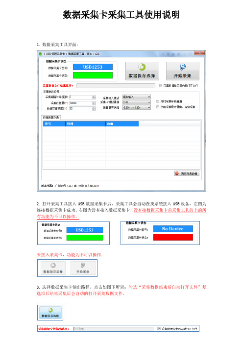
数据采集卡采集工具使用说明1. 数据采集工具界面:2. 打开采集工具接入USB数据采集卡后,采集工具会自动查找系统接入USB设备,左图为连接数据采集卡成功。
右图为没有接入数据采集卡,没有接数据采集卡前采集工具的上的所有功能为不可以操作。
未接入采集卡,功能为不可以操作:3. 选择数据采集卡输出路径,点击如图下所示:勾选“采集数据结束后自动打开文件”复选项后结束采集后会自动的打开采集数据文件。
4. 采集参数设置:A.采集间隔时间(毫秒):采集每次数据点之间的等待时间设置,设置为0表示不等待连续采集数据。
B.采集数据量(个):最大采集数量值,采集到最大值后程序自动停止结束。
勾选“勿略采集最大量值,连续采集”复选框后此设置将无效。
采集结束在点击“停止采集”按键后结束。
C.数据存储深度(个):存储深度主要解决实时显示数据软件所占用的时间,存储深度值越大显示数据越慢,此显示速度慢不影响正常采集速度,只是影响显示速度。
如采集时频率比较慢时需要设置采集间隔时间,把存储深度设置为1表示实时值。
D.采集接入模式:采集模拟分为三种:模拟输入(单极性),差分输入,真双极输入。
模拟输入只能采集大于0V以上的电压值,不能采集负电压。
差分输入可以测试正负电压,测试正负电压需要按差分方式接线,差分方式接线与地线无关。
真双极输入可以测试正负电压,可以直接测试负电压。
采集工具会根据采集卡类型显示不同的输入模式,工具只会显示支持的模式选择项。
详细支持输入模式请参考产品说明书参数规格。
E.采集卡输入通道:输入通道表示采集卡指定的采集通道,不同型号采集有不同数量的采集通道。
采集卡支持:单通道采集和全通道采集功能。
全通道采集功能可以勾选“同时采集所有通道”复选框。
F.采集量程选择:不同类型采集卡支持不同的量程选择,详细参数可以参考用户说明。
5.清空列表数据点击“清空列表数据”按键后会清除列表数据,注意:清空后的数据不可恢复:6.数据采集:点击“开始采集”按键后采集工具自动开始采集数据,点击“停止采集”后程序自动停止并保存采集数据。
采集卡操作

1.接线
模拟信号输出通道(Analog signal output):AO 通道(NI 6366)有两个输出通道:AO 0和AO 1. 另一根接对应的GND线。
模拟信号输入通道(Analog signal input): AI 通道。
一根接+,一根接GND。
2.程序设置(扫频范围从1kHz到300kHz)
目前实现功能是单发单收,发射扫频波;可以弄懂程序后,改变发的波,以及收波的形式。
扫频的范围最好越过这个共振值。
1)input rate(采样频率),单位为点数/秒(现在设置的为2000000,是仪器最大采样频率)2MS/s/ch, 每个通道,每秒钟,采集200万个样本点。
(奈奎斯特采样定理)早高频率段和低频率段,采集信号时的采样频率要求,本文采用6~7倍(一般为10倍)
2)扫频信号目前无法通过abaqus模拟;脉冲信号可以。
3)打开滤波按钮(学习程序滤波的原理)
4)损伤定位:2维,可以用3个pzt片;3维,合成孔径。
NIUSB_datasheetNI数据采集卡手册
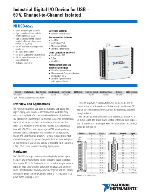
Industrial Digital I/O Device for USB –60 V, Channel-to-Channel IsolatedOverview and ApplicationsThe National Instruments USB-6525 is a full-speed USB device with eight normally open, channel-to-channel isolated, solid-state relay outputs and eight ±60 VDC channel-to-channel isolated digital inputs. The NI USB-6525 offers features for industrial control and manufacturing test applications, such as factory automation, embedded machine control, and production line verification. The solid-state relay outputs have a 60 VDC/30 V rms switching voltage and 500 mA/ch maximum switching current, making them ideal for controlling pumps, valves, motors, and other industrial actuators. The eight isolated digital input channels break ground loops and offer protection from noise and spikes on external signals. You can also use one of the digital input channels as a 5 kHz, 32-bit event counter for counting digital pulses.HardwareThe USB-6525 has eight channel-to-channel optically isolated inputs,P1.<0..7>, and eight channel-to-channel optically isolated, solid-state relay outputs, P0.<0..7>. The isolated inputs consist of an optocoupler, a depletion-mode MOSFET-based current-limiting circuit, and a Schottky diode. Each channel has its own positive and negative terminals capable of detecting a wide range of DC signals, from 5 V TTL logic levels to DC power supply levels up to 60 V.PFI 0 (an alias to P1.7) can also function as the source for a 32-bit counter. In this mode, the device counts low to high transitions on P1.7. You can arm and disarm the counter as well as read or reset the count through software.You can connect loads to the solid-state relay outputs with an AC or DC power source. The default power-on state of the solid-state relays is open. The relays also remain open when the computer and the USB-6525device are powered off.•Small, portable digital I/O device •Eight channel-to-channel optically isolated inputs (±60 VDC)•Eight channel-to-channel optically isolated, solid-state relay outputs (60 VDC/30 V rms max)•500 mA maximum switching current per channel•One 32-bit event counter•Full-speed USB (12 Mb/s) bus interface •Built-in, removable connectors for easy connectivity•USB cable strain relief Operating Systems•Windows Vista/XP/2000Recommended Software •LabVIEW•LabWindows™/CVI •Measurement Studio •LabVIEW SignalExpressOther Compatible Software •Visual Studio .NET•C, C++•Visual BasicMeasurement Services Software (included)•NI-DAQmx driver software •Measurement & Automation Explorer configuration utility•LabVIEW SignalExpress LEdata-logging softwareNI USB-6525IsolationIsolation is a form of built-in signal conditioning that provides an extended voltage range for direct connectivity to industrial sensors and actuators. The USB-6525 provides channel-to-channel isolation where each channel is physically and electrically separated from the others. Isolation provides three main benefits:1.Safety from hazardous high voltages and transients2.Rejection of common-mode voltages3.Removal of ground loopsSafety from High-Voltage TransientsIsolation electrically separates high-voltage front-end channels from each other and the low-voltage back end of the USB-6525. Signalsare passed between the two sections of the device using optocouplers. By separating the two sections, any voltages within the isolation specifications are prevented from entering the USB bus section or other channels. Isolation provides protection for the user, data acquisition system, and measurement data.Common-Mode Voltage RejectionA voltage common to both sides of a differential circuit pair iscalled common-mode voltage. This phenomenon is typical in noisy environments containing machinery and inductive loads. The differential voltage across the circuit pair is the desired signal, whereas the common voltage signal is the unwanted signal that may have been coupled into the transmission line. The USB-6525 can measure signals from lines with signal plus common-mode voltage of up to 60 VDC.Ground Loop RemovalGround loops are the most common source of noise in data acquisition applications. They occur when two connected terminals in a circuit are at different ground potentials, causing current to flow between thetwo points. This additional voltage can cause significant error in the measurement. When a ground loop exists, the measured voltage isthe sum of the signal voltage and the potential difference that exists between the signal source ground and the measurement system ground. This potential is generally not a DC level; therefore, the result is a noisy measurement system. By offering an isolated floating ground on the front end, the isolated USB-6525 devices are able to prevent ground loops from forming.SoftwareNational Instruments measurement services software, built aroundNI-DAQmx driver software, includes intuitive application programming interfaces, configuration tools, I/O assistants, and other tools designed to reduce system setup, configuration, and development time. National Instruments recommends using the latest version of NI-DAQmx driver software for application development in National Instruments LabVIEW, LabWindows/CVI, and Measurement Studio. To obtain the latest version of NI-DAQmx, visit /support/daq/versions. NI measurement services software speeds up your development with features including:•A guide to create fast and accurate measurements with no programming using DAQ Assistant•Automatic code generation to create your application in LabVIEW; LabWindows/CVI; LabVIEW SignalExpress; and Visual Studio .NET,C/C++/C#, or Visual Basic using Measurement Studio •Multithreaded streaming technology•More than 3,000 free software downloads to jump-start your project available at /zone•Software configuration of all digital I/O features without hardware switches/jumpers•Free LabVIEW SignalExpress LE data-logging softwareThe USB-6525 is compatible with the following versions (or later) of NI application software – LabVIEW, LabWindows/CVI, and Measurement Studio versions 7.x or LabVIEW SignalExpress. You can also use your NI digital I/O device with ANSI C, Microsoft Visual C++, Visual Basic, and the Microsoft .NET languages C# and Visual Basic .NET. The USB-6525 is not compatible with the Traditional NI-DAQ (Legacy) driver.Ordering InformationNI USB-6525..........................................................................779640-01 Includes NI-DAQmx software, LabVIEW SignalExpress LE data-logging software, anda USB cable.NI USB-6000 Series Prototyping Accessory........................779511-01 Includes breadboarding area with cover and strain relief.SpecificationsThese specifications are typical at 25 °C, unless otherwise noted.Isolated InputsNumber of channels............................8, ch-ch isolatedInput voltage range.............................-60 to 60 VDCDigital logic levelsInput current........................................ 3.0 mA/channel maxSolid-State Relay OutputsNumber of channels............................8, ch-ch isolatedRelay type...........................................Normally open solid-state relay(SSR)Switching voltage...............................60 VDC/30 V rms max Switching current (per channel).........500 mA max, full operationtemperature range Switching rate (90% duty cycle)......... 5 operations per second Relay open time..................................60 µs typRelay close time.................................. 1.2 ms typOn-resistance......................................550 mΩ, maxOff-leakage current (max)...................0.6 µA typCounterNumber of counters............................ 1 (P1.7 can be configured asa counter) Resolution...........................................32 bitsCounter measurements.......................rising edge counting Maximum input frequency.................. 5 kHzMinimum high pulse width.................20 µsMinimum low pulse width..................180 µsBus InterfaceUSB B 2.0 full-speed (12 Mb/s)Power RequirementsInput voltage....................................... 4.5 to 5.25 VDC in configuredstateActive current......................................150 mA maxSuspend current..................................350 µA typPhysical CharacteristicsDimensionsWithout connectors........................ 6.35 by 8.51 by 2.31 cm(2.50 by 3.35 by 0.91 in.)With connectors.............................8.18 by 8.51 by 2.31 cm(3.22 by 3.35 by 0.91 in.)I/O B series B receptacle,(2) 16 position (screw terminal)plug headers Screw-terminal wiring........................16 to 28 AWG copper conductorwire with 10 mm (0.39 in.) ofinsulation stripped from the end Torque for screw terminals.................0.22 to 0.25 N · m(2.0 to 2.2 lb in.)WeightWith connectors.............................Approx. 87 g (3.1 oz)Without connectors........................Approx. 64 g (2.3 oz)IsolationChannel-to-channel ............................60 VDC continuousChannel-to-earth ground ....................60 VDC continuous Withstand ..........................................60 VDC continuousNote:Do not use this module for connection to signals or for measurements within Measurement Categories II, III, or IV. EnvironmentNI 6528 and PXI-6529 devices are intended for indoor use only. Pollution degree (IEC-60664) (2)Operating EnvironmentAmbient temperature .........................0 to 55 °CRelative humidity................................10 to 90%, noncondensing Maximum altitude ..............................2,000 m at 25 °C ambienttemperature(tested in accordance with IEC-60068-2-1, IEC-60068-2-2, and IEC-60068-2-56)Storage EnvironmentAmbient temperature .........................-40 to 85 °CRelative humidity ...............................5% to 95%, noncondensing (tested in accordance with IEC-60068-2-1, IEC-60068-2-2, and IEC-60068-2-56)Safety and ComplianceSafetyThis product is designed to meet the requirements of the following standards of safety for electrical equipment for measurement, control, and laboratory use:•IEC 61010-1, EN 61010-1•UL 61010-1, CSA 61010-1Note:For UL and other safety certifications, refer to the product label or visit /certification, search by model number or product line, and click the appropriate link in the Certification column. Electromagnetic CompatibilityThis product is designed to meet the requirements of the following standards of EMC for electrical equipment for measurement, control, and laboratory use:•EN 61326 EMC requirements; Minimum Immunity•EN 55011 Emissions; Group 1, Class A•CE, C-Tick, ICES, and FCC Part 15 Emissions; Class ANote:For EMC compliance, operate this device according toproduct documentation.CE ComplianceThis product meets the essential requirements of applicable European Directives, as amended for CE marking, as follows:•73/23/EEC; Low-Voltage Directive (safety)•89/336/EEC; Electromagnetic Compatibility Directive (EMC) Note:Refer to the Declaration of Conformity (DoC) for this product for any additional regulatory compliance information. To obtain the DoC for this product, visit /certification, search by model number or product line, and click the appropriate link in the Certification column.Waste Electrical and Electronic Equipment (WEEE)EU Customers:At the end of their life cycle, all products must be sent to a WEEE recycling center. For more information about WEEE recycling centers and National Instruments WEEE initiatives, visit/environment/weee.htm.NI Services and SupportNI has the services and support to meet your needs around the globe and through the application life cycle – from planning and development through deployment and ongoing maintenance. We offer services and service levels to meet customer requirements in research,design, validation, and manufacturing. Visit /services .Training and CertificationNI training is the fastest, most certain route to productivity with our products. NI training can shorten your learning curve, save development time, and reduce maintenance costs over the application life cycle. We schedule instructor-led courses in cities worldwide, or we can hold a course at your facility. We also offer a professional certification program that identifies individuals who have high levels of skill and knowledge on using NI products. Visit /training .Professional ServicesOur NI Professional Services team is composed of NI applications and systems engineers and a worldwide National Instruments Alliance Partner program of more than 600 independent consultants andintegrators. Services range from start-up assistance to turnkey system integration. Visit /alliance .OEM SupportWe offer design-in consulting and product integration assistance if you want to use our products for OEM applications. For information about special pricing and services for OEM customers, visit /oem .Local Sales and Technical SupportIn offices worldwide, our staff is local to the country, giving you access to engineers who speak your language. NI delivers industry-leading technical support through online knowledge bases, our applications engineers, and access to 14,000 measurement and automationprofessionals within NI Developer Exchange forums. Find immediate answers to your questions at /support .We also offer service programs that provide automatic upgrades to your application development environment and higher levels of technical support. Visit /ssp .Hardware ServicesNI Factory Installation ServicesNI Factory Installation Services (FIS) is the fastest and easiest way to use your PXI or PXI/SCXI combination systems right out of the box.Trained NI technicians install the software and hardware and configure the system to your specifications. NI extends the standard warranty by one year on hardware components (controllers, chassis, modules)purchased with FIS. To use FIS, simply configure your system online with /pxiadvisor .Calibration ServicesNI recognizes the need to maintain properly calibrated devices for high-accuracy measurements. We provide manual calibration procedures, services to recalibrate your products, and automated calibration software specifically designed for use by metrology laboratories. Visit /calibration .Repair and Extended WarrantyNI provides complete repair services for our products. Express repair and advance replacement services are also available. We offerextended warranties to help you meet project life-cycle requirements. Visit /services.National Instruments • info@ • 800 813 3693*351494A-01*351494A-012007-8768-301-101-D。
用NI USB-6363采集数据

总结一下用NI USB-6363采集卡采集数据的使用流程,使用软件为LabVIEW Signal Express2010:(1) 连线。
(分差分,RSE,NRSE三种)(2) 打开Measurement&Automation,在左侧列表中,点开设备和接口,会发现NI USB-6363 ‘Dev1’,接着进行自检,如果硬件正常,则会显示硬件通过自检。
(3) 从左侧的软件列表中选择LabVIEW SignalExpress 2010,启动。
(4) 在Add Step里选择Acquire Signals→DAQmx Acquire→Analog Input →Voltage。
在Add Channels To Task下面选择所需测试的Channel。
如Dev1_ai0(下面类似)。
(5) 右侧默认的最大最小电压值不用改。
Terminal Configuration选择RSE (因为连线方式选的是RSE)。
Acquisition Mode选择Continuous Samples。
Samples to Read和Rate视情况具体设置。
假设所测信号为1k,峰峰值1V的正弦波。
则,采样率Rate可设置为10k(需要大于信号两倍),采样点数Samples to Read可设置为100(10ms:10个周期)。
(6) 在Triggering的选项里,Trigger Type可选择Software。
后面的Trigger Source选择A。
Advanced Timing和Execution Control可不做设置。
此时,点击Run,再点击trigger A(此处是根据上面的触发方式选的,不同触发方式操作不一样)。
此时在Preview下可以预览采集到的信号。
在Data View下可以像示波器一样显示的波形。
(7) 在Data View界面下,右击,signals→add signals→选择Dev1_ai0→OK.此时可以看到采集到的波形,如下所示:(8) 为了保存采集的数据,可使用数据I/O功能。
数据采集卡使用方法

数据采集卡使用方法
数据采集卡是一种用于采集和记录数据的设备,通常与计算机或控制系统配合使用。
以下是使用数据采集卡的一般步骤:
1. 安装数据采集卡驱动程序:在使用之前,首先需要安装数据采集卡的驱动程序。
驱动程序通常由数据采集卡制造商提供,并可从他们的网站下载。
2. 连接传感器或数据源:将需要采集数据的传感器或数据源连接到数据采集卡上。
这通常通过插入传感器的接口或连接电缆实现。
3. 配置数据采集卡:打开数据采集卡的配置软件,选择采集通道和采集参数。
采集通道可以是模拟通道(用于测量模拟信号)或数字通道(用于接收数字输入信号)。
采集参数包括采样率、分辨率等。
4. 启动数据采集:在配置完成后,可以启动数据采集。
数据采集卡将开始采集传感器或数据源的数据,并将其传输到计算机或控制系统中进行处理或记录。
5. 数据处理和分析:采集到的数据可以通过计算机上的软件进行处理和分析。
这可以包括数据的实时显示、数据过滤、数据转换、统计分析等。
需要注意的是,不同的数据采集卡可能具有不同的配置和使用方法,根据具体的数据采集卡型号和制造商提供的说明书来操作会更加准确和有效。
NI采集卡的多通道不同功能采集的配置操作方法

NI采集卡的多通道不同功能采集的配置操作方法1. 打开NI采集卡的配置软件:首先需要打开NI采集卡对应的配置软件,例如NI-DAQmx或者LabVIEW,这些软件提供了图形化界面和API 接口来配置和控制采集卡。
2.确定采集通道数目:在软件界面上,需要确定采集的通道数目,即同时采集的信号源数量。
根据具体应用需求,可以选择多通道采集配置。
3.配置采集参数:针对每个通道,需要配置采集参数,例如采样率、量程、触发模式等。
采样率是指每秒采样的次数,量程是指信号的幅度范围,触发模式是指启动采集的条件。
4.设定物理连接:将各个信号源与采集卡的输入端口进行物理连接。
通常,使用BNC线缆将信号源连接到采集卡的输入通道。
5.配置数据存储方式:在采集卡配置软件中,可以选择数据存储的方式。
可以选择将数据保存在计算机的硬盘中,或者直接存储在采集卡的内存中。
6.设置数据处理功能:如果需要对采集到的数据进行进一步的处理,可以在配置软件中设置数据处理功能。
例如,可以选择进行滤波、数字信号处理、实时显示等操作。
7.验证配置:在完成配置后,可以进行配置的验证。
可以通过软件提供的测试功能,发送一个已知的测试信号,并观察是否能够正确采集到该信号。
8.启动采集:完成配置后,可以启动采集操作。
可以通过配置软件提供的开关按钮或者编程接口来启动采集操作。
一旦启动,采集卡将开始按照配置的参数进行数据采集。
9. 数据后处理:采集完数据后,可以进行数据后处理操作。
可以使用MATLAB、LabVIEW等软件进行数据分析、图像显示等。
总结:NI采集卡的多通道不同功能采集的配置操作方法包括打开配置软件、确定通道数目、配置采集参数、物理连接、配置数据存储方式、设置数据处理功能、验证配置、启动采集和数据后处理。
通过这些步骤,可以正确配置NI采集卡以满足不同应用的需求。
NI PXIe-6124数据采集卡说明书
800 k
1M
Frequency (Hz)
Magnitude (dB)
2 0 –2 –4 –6 –8 –10
1k
Frequency Response, All Ranges
10 k
100 k
1M
Frequency (Hz)
10 M
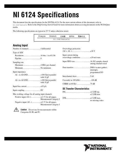
NI 6124 Specifications
2
© National Instruments Corporation
Overvoltage protection (AI +, AI –)......................................±36 V
Input current during overvoltage conditions ....................±20 mA max
Interchannel skew............................5 nS
Crosstalk (at 100 kHz).....................–100 dB
CMRR (at 60 Hz) ............................75 dB
DC Transfer Characteristics
Type of ADC Resolution................................... 16 bits, 1 in 65,536 Pipeline....................................... 0
用NI的数据采集卡实现简单电子测试之1——USB-6009简介
⽤NI的数据采集卡实现简单电⼦测试之1——USB-6009简介本⽂从本⼈的163博客搬迁⾄此。
⼏年以来,⼀直担任学校“虚拟仪器”课程教师。
以前上课都以介绍LabVIEW编程为主,硬件实验⼀直没有开展。
这次借“西部⾼校实⼒提升⼯程”的机会,学院采购了⼀批NI的数据采集卡,终于有机会让学⽣动⼿开展⼀点硬件实验了。
这次采购的是⼊门级的USB数据采集卡——USB-6009,NI没有为这卡提供外围实验电路,要⽤他上实验课还得⾃⼰动⼿为这个“⼩宝贝”设计⼏个实验,并配些外围电路。
接下来的⼏篇博⽂,将分⼏次介绍为学⽣设计的实验及外围电路,写到哪算哪吧。
今天先从⼩宝贝⼯具USB-6009介绍起。
(NI官⽅⽹站上介绍资料的内容就不原样重复了,只把我觉得有⽤、有趣和⼤家会感兴趣的内容摘⼀下)在NI众多的数据采集卡中,USB-6009可以算是性能最低的了,价格也相对最低——官⽅渠道约⼩3000元(个⼈觉得还是⽐国产的其他数据采集卡还是贵多了)。
USB-6009性能不⾼,但“⿇雀虽⼩,五脏俱全”,常见的功能⼀应俱全,基本能够体现LabVIEW+NI数据采集卡的开发特点。
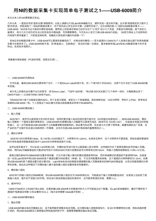
先来张外观照⽚。
再看看内部电路板(PCB的顶层,底层没东西)。
⼀、USB-6009的内部构成打开后盖,看到USB-6009主要有两个芯⽚,⼀个是Silicon Labs的单⽚机,另⼀个是TI的⼗四位ADC,这两个芯⽚决定了USB-6009的基本性能。
单⽚机上的激光丝印看不出它的型号,但“Silicon Labs”、“TQFP-32封装”、“有USB DEVICE接⼝”⼏个条件⼀综合,⼤概能猜出来了:C8051F320——2.3KB RAM+16KB Flash。
TI的ADS7871是个功能挺全⾯的ADC。
四个全差分通道,或变为⼋个单端通道。
其他参数包括:14位分辨率;带有⽚上PGA;参考电压等都和USB-6009⼀样。
个⼈觉得这个ADC最⼤的缺点就是最⾼采样率只有48KBPS。
- 1、下载文档前请自行甄别文档内容的完整性,平台不提供额外的编辑、内容补充、找答案等附加服务。
- 2、"仅部分预览"的文档,不可在线预览部分如存在完整性等问题,可反馈申请退款(可完整预览的文档不适用该条件!)。
- 3、如文档侵犯您的权益,请联系客服反馈,我们会尽快为您处理(人工客服工作时间:9:00-18:30)。
NI 数据采集卡使用入门NI 数据采集卡使用入门一、安装与配置:1. 在安装板卡之前,请首先安装NI-DAQ驱动程序软件。
您可以在随卡附带的光盘内找到这个驱动程序软件。
另外,NI公司的网站上也提供这个驱动程序软件的免费下载:/softlib.nsf/websearch/90B60D5899BCCCDB86256FC700581B89?opendocument&node=132070_US如果您使用LabVIEW或LabWindows/CVI 等软件来进行编程,需要在安装驱动软件之前先安装开发平台LabVIEW或LabWindows/CVI等软件。
安装过程中,安装程序会提醒您插入DAQ驱动光盘。
2. NI-DAQ驱动软件正确安装后,请关闭计算机,插入数据采集板卡,启动计算机,即可自动找到板卡并安装好,完成整个安装过程。
注意:在安装PCI或者PXI板卡时,一定要将电脑电源关闭;PC机则最好将电源线拔掉,以免电脑主板关机后仍然带电,造成各类损伤。
二、模拟输入说明1. 信号类型根据信号的参考情况,一个电压源可以分为两类:接地信号、浮地信号。
接地信号:接地信号是信号的一端直接接地的电压信号。
它的参考点是系统地(例如大地或建筑物的地)。
最常见的接地信号源是通过墙上的电源插座接入建筑物地的设备,例如信号发生器和电源供电设备等。
浮地信号:一个不与任何地(如大地或建筑物的地)连接的电压信号称为浮地信号。
一些常见的浮地信号有电池、热电偶、变压器和隔离放大器。
2.测量方式按信号连接方式不同可分为三种测量方式:差分(DIFF);参考单端(RSE);非参考单端(NRSE)。
注意:NI公司的部分型号数据采集卡不一定完全支持上述三种测量方式,请查询对应数采卡的使用手册。
按测量方式分类可以分为以下两大类测试系统:1)差分测试系统(DIFF)n 可避免接地回路干扰n 可避免因环境引起的共模干扰当输入信号有以下情况时,使用差分测试系统:n 低电平信号(例如小于1V)。
n 信号电缆比较长或没有屏蔽,环境噪声较大。
n 任何一个输入信号要求单独的参考点。
2)单端测试系统尽管差分测试系统是一种比较理想的选择,但是单端测试系统可以使用两倍的测试通道。
单端测试系统所有信号都参考一个公共参考点,即仪器放大器的负极。
当输入信号符合以下条件时可以使用单端测试系统:n 高电平信号(通常大于1V)。
n 距离比较短(通常小于5米)或电缆的屏蔽性能较好,环境无噪声。
n 所有信号可以共享一个公共参考点。
单端测试系统分为参考单端测试系统和非参考单端测试系统。
A 参考单端(RSE)n 参考单端测试系统用于测试浮地信号,它把信号参考点与仪器模拟输入地连接起来。
B.非参考单端(NRSE)n 可避免接地回路干扰非参考单端测试系统用于测试接地信号。
与参考单端测试系统不同的是因为所有输入信号都已经接地了,所以信号参考点不需要再接地。
针对上述信号使用的接线方式具体请参考下图:一般来说:接地信号的测量,可以用差分或非参考单端方式;浮地信号的测量,可以用上述三种测量方式;此外,在用差分和非参考单端测量方式时,为避免叠加在输入端的共模电压(仪器放大器输入端相对于仪器放大器接地端之间的电压)超出允许范围,需在测量端与测量地之间连接偏置电阻。
3 偏置电阻的选择一个信号源必须有参考地AIGND(模拟地)。
下图表示了在浮地信号源下,并行连接两个偏置电阻。
如果你没有连接电阻,信号源浮地,信号源就不可能一直保持程控增益放大器(PGIA)的共模信号范围,程控增益放大器将饱和,而导致读数不准。
如果信号源阻抗小于100欧,最简单的方法是将信号的正端接到PGIA的正端,信号的负端接AIGND,也接到PGIA的负端输入,不用接任何电阻。
如果信号源阻抗大于100欧:1)如果采集卡有交流耦合功能并启用(即采集卡内部有前端处理电路,可以去掉信号源的直流分量(一般方法为串联电容)):PGIA需要在正端输入和AIGND之间加一个电阻(R1)。
如果信号源为低阻抗,R1可选择阻值为100kW 到1MW,负端直接连到AIGND(即R2=0);如果信号源为高阻抗,一般选择在正负端各接一个电阻R1和R2(R1=R2)。
2) 如果采集卡没有交流耦合功能或者不启用:A. 如果信号源阻抗比较大,直接连接会有不平衡的差分信号。
噪声静电耦合给了正端,但由于负端接地却没耦合给负端,因此噪声显示为差分信号而不是共模信号,PGIA并不接收它。
在这种情况下,需要将信号源负端通过一个电阻(R2)连到AIGND,而不是直接连接到AIGND,电阻值大概为信号源阻抗的100倍。
这个电阻将平衡两路信号,将噪声同时耦合到两端。
B. 你也可以在正端和AIGND之间再连接一个电阻R1(R1=R2),来充分平衡信号。
这种接法有利于更好的抗噪,但是两个电阻对信号源也会造成负担过重。
注意:接R1,R2之后测量信号的幅值会有-1%的误差。
4.NI常用数采卡接线方法简介以PCI-6052E(68pin)为例,简单介绍一下不同测量方式的接线方法。
下图是PCI-6052E数采卡的引脚定义图:(1)差分(DIFF)测量方式:使用2根模拟输入接线,信号一端连接在PGIA正端,另一端连接在PGIA负端。
板卡上正负端接线通道的关系:正端为ACHi,负端为ACH(i+8),(i=0..7),依此类推。
例如:使用数采卡的0通道,信号源接ACH0(68号引脚),负端接ACH8(34号引脚)。
(2)参考单端(RSE)测量方式:使用1根模拟输入接线,信号一端连接在PGIA正端,另一端连接在系统地端(AIGND)。
板卡上正端为ACHi,系统地端为AIGND。
例如:使用数采卡的0通道,信号源正端接ACH0(68号引脚),负端接AIGND(67号引脚)。
注:所有AIGND在板卡内部直接连通共地。
(3)非参考单端(NRSE)测量方式:使用1根模拟输入接线,信号一端连接在PGIA正端,另一端连接在非系统地的共同端(AISENSE)。
板卡上正端为ACHi,共同端为AISENSE。
例如:使用数采卡的0通道,信号源正端接ACH0(68号引脚),负端接AISENSE(62号引脚)。
注:如用差分或非参考单端测量方式,注意偏置电阻的选择。
(详见3 偏置电阻的选择)(4)常见引脚定义:ACHx:模拟输入端;若使用差分方式则正负端对应关系为:ACHi,ACH(i+8),(i=0..7)。
AIGND: 模拟输入参考地接入方式参考端;AISENSE: 模拟输入非参考地接入方式参考端;三模拟输出说明需要将输出正端接AOx,负端接AOGNDx。
1 下图表示了NI数据采集卡上的模拟输出的连接方法:2 模拟输出端名称原始输出端名称实际命名作用DAC0OUTAO0模拟输出通道0 DAC1OUTAO1模拟输出通道1 EXTREFAO EXT REF模拟输出外部参考AOGNDAO GND模拟输出地例如:如果使用数采卡的1通道,就将输出正端接AO1(21引脚),负端接AOGND1(54引脚)。
四数字I/O需要将输出正端接DIOx,负端接任意一个DGND。
1 各种设备的数字端口数量有所不同。
下图表示了三种典型的数字I/O应用的连接方式:图中P0<0..3>配置为数字输入,P0<4..7>配置为数字输出。
数字输入应用包括接收TTL信号和接收外部设备状态(例如开关状态)。
数字输出应用包括发送TTL信号和驱动外部设备(例如图示中的LED)。
例如:如果使用数采卡DIO的1通道作为输出,就将输出正端接DIO1(17引脚),负端接任意一个DGND (如18引脚)。
五计数器计数器测量和产生数字信号。
常用于测量信号频率或者信号周期。
信号连接方式根据不同的设备要求而不同。
以6052E为例:测常规时间(包括脉冲宽度,周期,频率):直接将待测信号正端接入计数器的SOURCE端(如计数器1的42引脚),信号负端接板卡的任意数字地(如35引脚);GATE(41引脚)可不接信号,使用内部时基(不用接线,软件定义);OUT(40引脚)可产生脉冲或脉冲序列。
测高频:可用两个计数器:计数器0的SOURCE(37引脚)使用内部时基(不用接线,软件定义),计数器0的OUT(2引脚)接计数器1的GATE(41引脚),待测频率接计数器1的SOURCE(42引脚)。
下列表是不同计数测量的输入接线端口。
测量Ctr0 (计数器0)Ctr1 (计数器1)边沿计数边沿:PFI8计数方向:PFI11边沿:PFI3计数方向:PFI11脉宽测量PFI9PFI4周期/频率测量(低频用1个计数器)PFI9PFI4周期/频率测量(高频用2个计数器)PFI8PFI3周期/频率测量(大范围用2个计数器)PFI8PFI3半周期测量PFI9PFI4下列表是计数器输出的输出接线端口,你可以使用不同的PFI线。
Ctr0 (计数器0)Ctr1CTR 0 OUT(2引脚)CTR 1 OUT(40引脚)以M 系列数采卡举例:下表是不同计数测量的缺省输入接线端口。
对任何输入端口,你可以使用不同的PFI线。
对于改变测量的PFI缺省输入,需要利用NI-DAQmx 通道属性在程序中设置。
测量Ctr0 (计数器0)Ctr1 (计数器1)边沿计数边沿:PFI8计数方向:PFI11边沿:PFI3计数方向:PFI11脉宽测量PFI9PFI4周期/频率测量(低频用1个计数器)PFI9PFI4周期/频率测量(高频用2个计数器)PFI8PFI3周期/频率测量(大范围用2个计数器)PFI8PFI3半周期测量PFI9PFI4两沿分离测量开始:PFI10停止:PFI9开始:PFI11停止:PFI4位置测量A:PFI8B:PFI10Z:PFI9A:PFI3B:PFI11Z:PFI4下列表是计数器输出的输出接线端口,你也可以使用不同的PFI线。
Ctr0 (计数器0)Ctr1PFI 12PFI 13。