华大自控说明书
WITT Gas Controls OXYBABY M+ 氧浓度 CO2组合分析仪说明书

Cordless handheld oxygen or combined oxygen/carbon dioxide analyzer for checking modified atmospheres in food packaging (MAP). The ideal instrument for portable, fast and accurate sample tests at the pack-aging machine, in stores or in laboratories. OXYBABY® M+: a cost-effective, mobile alternative to tabletop/fixed analyzers.Ensure that the quality of your packaged productis maintained (HACCP), guaranteeing continued customer satisfaction.OXYBABY® M+ is the ideal instrument for sample tests, requiring only a minimal amount of sample gas, allowing even the smallest of MAP packages to be tested.Featuring an integrated data log of the last 100 measurements assigned to specific product names or line numbers.Benefits●minimal sample gas requirement for testing even the smallest packages●cordless operation using rechargeable batteries●simple one-hand operation●sample flow control with warning in case of blocked needle●easy to clean●large illuminated graphic display●measurement alternatively also by hose●multilingual menu guide: see overleaf●integrated needle cover to protect needle and user●long lifetime of O2 sensor(approx. 2 years, depending on use)●low maintenance costsComplete in carrying case●charging device and adaptor set●15 spare needles●5 spare filters●set of 100 rubber seals●case dimensions (HxWxD): approx. 12.79 x 15.16 x 4.53 inches case weight: approx. 3.75 lb OXYBABY® M+ O2- Part No. 590000313OXYBABY® M+ O2/CO2- Part No. 590000305 Options●hose with Luer-Lok connection for stationary measurement●can/bottle piercer●table rack/standPlease note our variety of accessories on the following pages!►Videofurther information onO X Y B A B Y ® M + O 2O X Y B A B Y ® M + O 2/C O 2● ●GasesO 2 balance gas: N 2, (Ar or others upon request)O 2 and/or CO 2 balance gas: N 2, (Ar or others upon request)●●Measuring principle O 2electrochemical cell ●Measuring principle CO 2IR-absorption●●Sensor lifetime O 2approx. 2 years (in air at 68°F)●Sensor lifetime CO 2long lifetime ●●Measuring range0-100%●● ●O 2 in 0.01%-steps CO 2 in 0.1%-steps●●Sample gas requirement < 10 ml ●●Sample time max. 10 sec.●●Calibration simple two-point calibration●●Sampling automatic via needle using integrated pump●●Data log last 100 measurementsassignment of measurements to different product names or line numbers ●●MultilingualGerman, English, French, Italian, Dutch, Swedish, Finnish, Spanish, Polish and Russian●●Temperature (gas/environment)32 – 104°F ●●Display backlit●●Shut down automatic after 2 minutes of non-use ●●Housing shock-resistant plastic●●Weightapprox. 1.32 lb (without accessories)●●Dimensions (HxWxD)7.4 x 4.2 x 3.6 inches (without needle)●●Power supply 3 integrated rechargeable batteries, type Ni-MH (charging device included)●●Charging device 110 – 240 V AC●●ApprovalsCompany certified according to ISO 9001 and ISO 22000CE-marked according to: - EMC 2014/30/EU- Low Voltage Directive 2014/35/EU for food-grade gases according to: - Regulation (EC) No 1935/2004Designed for Oxygen Service in accordance with EIGA 13/20 and CGA G-4.4: Oxygen Pipeline and Piping Systems Cleaned for Oxygen Service in accordance with EIGA 33/18 and CGA G-4.1: Cleaning of Equipment for Oxygen Service。
全自动冷库控制器说明书

冰山嘉德全自动冷库控制器(V1.0)●控制和人机交互界面采用独立的分体式设计,便于灵活配置。
●3个控制风机运行的继电器输出。
●1个控制供液电磁阀的继电器输出。
●1个控制回气电磁阀的继电器输出。
●1个控制旁通电磁阀的继电器输出。
●1个控制热氨冲霜电磁阀的继电器输出。
●1个控制水冲霜电磁阀继电器输出。
●1个控制排水管加热的继电器输出。
●1路用于自动控制的压力传感器或湿度传感器(4~20mA)信号输入。
●2路或4路(回风、出风)温度传感器信号输入。
●1路风机电流信号输入(电流互感器二次输出电流0~5A,可选)。
●9个用于控制和安全保护的开关量输入。
●控制器供电电源:24Vdc。
●控制部分有两个完全独立的RS485通信端口。
COMA用于和显示器相连,COMB为今后扩展备用。
●显示部分也有两个完全独立的RS485通信端口。
一个用于和控制器相连,另一个用于和上位机通信,进行远程控制和管理。
●通信采用RS485 Modbus RTU协议。
运行手册概述全自动冷库控制器(以下简称控制器)作为冰山嘉德公司因应当今信息化大潮提出的透明冷库概念的一部分,具有网络通信和远程控制功能。
该控制器可根据冷库运行状况实行对冷库的相关设备进行自动控制。
除此之外,它可以经过通信网络将冷库运行的工作状态及相关数据送往上位机,以便进行远程监控。
本手册是控制器的使用及操作说明,在手册中详细的说明了控制器的使用场合、功能用途、外部接线方式、参数设定方法、具体操作步骤、按钮功能说明、故障信息解释等内容。
使用控制器前,用户务必先详细阅读并了解本手册的内容。
一、工作原理全自动冷库控制器是一种利用微处理器数字控制技术对冷库进行全自动控制的装置。
它实时地对回风及出风温度进行跟踪采样,对冷库冷设备的工作状态进行检测,并按照设定的控制参数和控制逻辑对冷库设备(风机、加热器、供液、冲霜)进行控制。
全自动冷库控制器由两部分组成:GC1719-LCS控制单元和CAM1-LCS操作显示单元。
华大参数设置说明
0~1
位置指令脉冲方向取反15
1
0~1(不是0就是1)
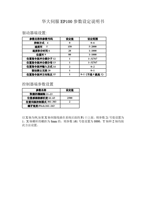
控制器端参数设置
参数名称
设定值
對應的機械軸21~23
位置感測器解析度61~63
2500
位置伺服控制模式381~383
2
螺牙寬度(Pitch)161~163
以X轴为例,如果X轴伺服线插在系统后面的P1口上面,则参数21号值设置为1,X轴螺杆的螺距为8mm的,则参数161号值设置为8000,Y轴和Z轴均按此方法设置。
华大伺服EP100参数设定说明书
驱动器端设置:
参数名称和参数号码
设定值
设定范围
控制方式4
0
0~6
速度环5
150
5~2000
速度积分时间6
20
1~1000
位置环9
80
1~1000
位置指令脉冲分频冲分频分母13
1
1~32767
位置指令脉冲输入方式14
2
0~2
驱动禁止无效20
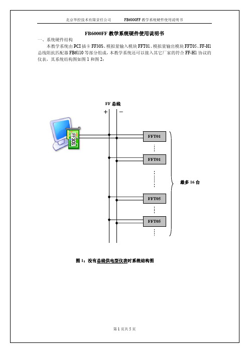
FB6000FF教学系统硬件使用说明书
4~20mA电流信号,必须在接线端子上跨接一250欧姆、精度为0.05%的精密电阻,将该信号转换为相应的电压信号,再送给模块。
技术参数:1、供电电源:24Vdc±10%2、电源耗电:120mA MAX3、输入信号:1~5Vdc4、输入通道:45、输入方式:差动6、精度:±0.1%FS7、设备类型:本地供电型8、总线:FF-H19、通信速率:31.25K/BPS接线说明:图3和图4分别为输入电压信号和电流信号时的接线图。
图中“O-O -BUS+O-O”表示“O-O”标号上方相临的两个接线端子在模块内部已短接,标有“O-O –24V+O-O”的端子也是一样的含义。
下同。
图3:1-5V电压信号接线图图4:4-20mA电流信号接线图三、FFT05模块:产品概述FFT05模块是2路4~20mA模拟信号输出单元,通过FF通讯接口接收FF总线上的输出数据,送给DAC转换,最后输出4~20mA电流信号。
该模块最大负载为500欧姆。
技术参数:1、供电电源:24Vdc±10%2、电源耗电:160mA MAX3、输出信号:4~20mA4、输出通道:25、输出方式:集电极开路6、精度:±0.2%FS7、负载电阻:500ΩMAX8、设备类型:本地供电型9、总线:FF-H110、通信速率:31.25K/BPS接线说明:图5为FFT05模块的接线图。
图5:FFT05模块接线图四、FB6110模块:产品概述FB6110模块是FF-H1总线阻抗匹配器,同FF电源配套使用给FF-H1现场总线仪表提供现场总线电源。
输出端子有4路,所有输出的同极在模块内部都是短接的,即物理上是一路输出。
技术参数:1、典型供电电源:FF专用电源或线性电源2、供电电源典型电压:24Vdc±10%3、供电电源纹波:20mVrms MAX4、输出电源电压:20.5±1Vdc5、电源负载能力:350mA MAX6、输出通道:1接线说明:FB6110模块接线图如图6。
自控系统操作手册

自控系统操作说明2018年3月20日目录第一章系统概述.......................... 错误!未定义书签。
1.自控系统的构成ﻩ错误!未定义书签。
1.1网络结构ﻩ错误!未定义书签。
1.2。
中控室设备配置4ﻩ1。
3。
PLC设备配置............................... 4第二章上位操作说明ﻩ52。
1.启动和登录系统................................ 52.2.系统控制画面简介 (5)第三章注意事项17ﻩ3。
1.计算机的维护清洁 (17)13.2.计算机的故障处理ﻩ7第一章系统概述本项目共有28个PLC主站,其中19座污水泵站PLC站为新建,3座污水泵站PLC 已有(需上下位机编程、与设备信号连接、调试),6座站PLC系统已建好(需上位机编程).在中控室设置有2台上位工业监控计算机。
通过VPN网络监控28座污水提升泵站,实现所有泵站的无人值守能自动,安全、可靠、稳定的运行。
1.自控系统的构成1.1网络结构每个提升污水泵站建立一个PLC站(已有的除外)。
现场PLC分别与现场电气控制柜信号连接,采集生产过程中的各种仪表参数,电气参数和机电等设备的工作状态,将采集到的数据、信号送到现场PLC柜,再通过VPN网络,最终显示在中心控制室上位机。
各控制站配置一套UPS不间断电源,控制站停电后仍能继续工作一段时间,中控室上位机并设置了断电报警功能,让中控室值班人员第一时间内及时关注停电泵站情况。
1。
2. 中控室设备配置中控室内设置有;2台两台操作站互为备用,正常工作时,两台计算机独立、并行运行,操作及状态在两台计算机之间同步进行,分别记录。
任何一台计算机出现故障时,另外一台计算机将保证系统的正常运行。
各计算机的IP地址为:操作站 OP1 :10。
100。
11.96OP2 :10.100。
11.102上位软件包括以下主要功能:✧用户登录✧泵站网络状态✧集水井液位实时显示及控制✧生产过程监视及控制✧报警显示、记录及打印✧实时曲线、历史曲线✧参数设置✧报表处理及打印1.3.PLC设备配置PLC站通信地址配置如下:129 富荣路172.20。
自控说明书
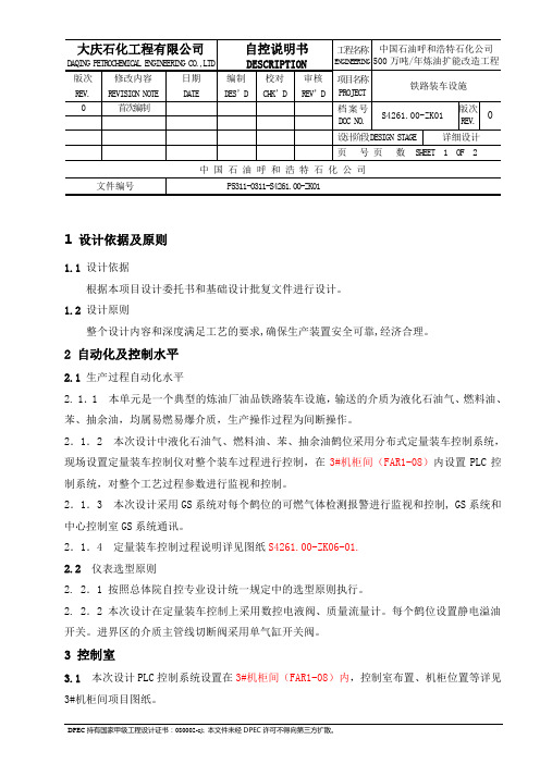
大庆石化工程有限公司D A QI N G PE T RO CH E MI CA L E NG I NE ER I NG C O.,LT D 自控说明书DESCRIPTION工程名称ENGI NEE RIN G中国石油呼和浩特石化公司500万吨/年炼油扩能改造工程版次修改内容日期编制校对审核项目名称PROJ ECT 铁路装车设施REV.REVI SIO N N OTE DATE DES’D CHK’D REV’D0 首次编制档案号DOC NO.S4261.00-ZK01版次REV.设计阶段DE SIG N S TAG E详细设计页号页数SHE ET1OF2中国石油呼和浩特石化公司文件编号P5311-0311-S4261.00-ZK011 设计依据及原则1.1 设计依据根据本项目设计委托书和基础设计批复文件进行设计。
1.2 设计原则整个设计内容和深度满足工艺的要求,确保生产装置安全可靠,经济合理。
2 自动化及控制水平2.1 生产过程自动化水平2. 1.1 本单元是一个典型的炼油厂油品铁路装车设施,输送的介质为液化石油气、燃料油、苯、抽余油,均属易燃易爆介质,生产操作过程为间断操作。
2.1.2 本次设计中液化石油气、燃料油、苯、抽余油鹤位采用分布式定量装车控制系统,现场设置定量装车控制仪对整个装车过程进行控制,在3#机柜间(FAR1-08)内设置PLC控制系统,对整个工艺过程参数进行监视和控制。
2.1.3 本次设计采用GS系统对每个鹤位的可燃气体检测报警进行监视和控制, GS系统和中心控制室GS系统通讯。
2.1.4 定量装车控制过程说明详见图纸S4261.00-ZK06-01.2.2 仪表选型原则2. 2.1 按照总体院自控专业设计统一规定中的选型原则执行。
2. 2.2 本次设计在定量装车控制上采用数控电液阀、质量流量计。
每个鹤位设置静电溢油开关。
进界区的介质主管线切断阀采用单气缸开关阀。
3 控制室3.1 本次设计PLC控制系统设置在3#机柜间(FAR1-08)内,控制室布置、机柜位置等详见3#机柜间项目图纸。
自控操作说明2012

检查UPS是否为开机状态,检查自控系统总电源开关是否为有电,可通过UPS主机上的指示灯(最左侧的市电指示灯)判断。详情可参见UPS的说明书。
2.厂区生产设备应急
2.1厂区断电预案
当厂房外部供电中断时,立即启用应急预案。
本自控系统配有不间断电源,当外部供电中断时,自控系统不受任何干扰,可以维持断电前数值的给定量(主要为频率给定值)。
3. 上位软件对变频的操作。
首先确认手自动状态处于自动,在频率设定后面设置给定频率。此时在变频器的操作面板中间##%数值为上位给定值,确认无误后在启停控制栏中选择起泵,然后点确定。在停泵时点击停泵按钮然后点确认。
三、组态界面操作
1. 组态界面在启动电脑时会自动进入运行模式,自动登录主画面。
2.选择用户登录
6.电动调节阀的操作
电动调节阀是控制工艺冷却水温度的重要环节,每个电动阀均配有手操器,手操器可在上位操作失效的情况下对电动阀进行控制。自动模式时,手操器左侧指示灯1、4亮,上位机可给定调节量。点击阀门图标,弹出阀位调节按钮,输入数值后点确定,该值为开度信号范围:0~100%。切换手动调节时,长按手操器“ENT”键3秒,第三个指示灯亮,此时可以通过手操器的上下键对阀门开度进行调节。
上位机禁止安装其他软件,为防止病毒及确保系统的稳定。
禁止操作人员进入组态软件开发环境,禁止修改组态参数。
四、自控方案
1.空调系统
共有4路控制回路,每个控制回路由几个阀门同时动作来保证该区域温度符合给定值,控制系统如图
2.动站系统
2.1铸锭冷却水供水总管压力变频控制系统(如图)
通过调节铸锭冷却水变频循环泵来保证供水总管压力符合给定要求。
2.2切片冷却水供回水差压变频控制系统(如图)
Cascade 强度控制系统用户指南说明书

cascadecorporationCascade is a Registered Trademark of Cascade CorporationManual Number 6923662Hydraulic Force ControlCarton Clamp on Raymond 4250 Truck (2017), Kit 6923464CONTENTSPageOVERVIEW1INSTALLATION2Prepare Attachment Valve2HFC Valve3Equalizer Valve3Heavy Load Override Valve3Hoses4Wiring5Disabling HFC System8SETUP9OPERATION11TROUBLESHOOTING12GLOSSARY14i692366216923662OVERVIEWHYDRAULIC FORCE CONTROL (HFC)This manual provides installation instructions for theCascade Hydraulic Force Control (HFC) system for Carton Clamps. If you need additional information or assistance, contact Cascade Corporation. Refer to the back cover.What The System DoesThe HFC system enables Cascade Carton Clamps to automatically apply clamp force proportional toweight of the load. This system will reduce the chance of damage caused by excessive clamp force.How The System WorksAn initial no-slip starting pressure is applied to the load when it is first clamped. As the load is lifted, the HFC system increases clamp force and applies a consistent clamp force proportional to load weight. The hoist system provides pressure to the HFC to increase clamp pressure as hoist pressure increases.Prior to InstallationThe system can be calibrated to balance the clamp force relationship of clamp capacity and truck size. The truck HOIST pressure should be equal to or higher than clamp pressure to properly clamp the load. Total weight equals load weight plus clamp weight.Confirm that the truck size is compatible with the clamp capacity. Available maximum hoist pressure with load weight (combined maximum size load and weight of the clamp) should be determined in freelift. The hoist pressure determined needs to be within 10% of the clamping pressure required to clamp the heaviest load.269236621 Open attachment arms to frame width.2 Disconnect the hydraulic hoses from the valve CLAMP(CL), OPEN (OP), SIDESHIFT RIGHT (SSR) and SIDESHIFT LEFT (SSL) ports.3 Remove CL port special fitting with spool or orifice pipe plug.4 Install kit pipe plug into CL port and reinstall fittingleaving spool out (as needed for G-Series valves).D-Series Valves – .25 in. dia. NPTF plug (Part No. 6603)G & J-Series Valves – .3125 in. dia. setscrew (Part No. 5304)Sideshift Front View36923662INSTALLATIONHFC VALVE1 Remove the capscrews fastening the lowering controlin the kit.1 Turn the truck valve solenoid coil to position theconnectors upward. This makes clearance for the override valve.2 Remove the plug from the truck valve tank port. Mayrequire a 5/8 in. extractor to remove the plug. Install a No. 10-8 fitting in the port.3 Install the tube to the override valve IN port and truck valve tank port. The valve will be laying on truck hoses, turn the valve downward for clearance.4 Install a No. 8 45° fitting to the valve fitting.2 Install the HFC valve to the bracket.HEAVY LOAD OVERRIDE V ALVE3 Install tubes to the valve top fittings.MastHoist46923662INSTALLATIONAC3383.eps1 Connect a No. 8 hose (6898920) from the T port on theHFC valve to the OUT port on the Override Valve.2 Disconnect the hose from the truck valve AR port.Connect the hose to the HFC valve OP2 port tube.3 Disconnect the hose from the truck valve AC port. Connect the hose to the HFC valve CL2 port tube.4 Connect No. 6 hose (6923278) from the truck valve AR port to the OP1 port of the HFC valve.5 Connect No. 6 hose (6923155) from the truck valve AC port to the CL1 port of the HFC valve.6 Install a No. 8-4-8 Tee fitting to the bottom of thelowering control valve. Connect No. 4 hose (6923279) from the H port on the HFC valve to the Tee fitting.Attachment ValveHOSESRaymond Valve ACconnects toRaymond Valve ARINSTALLATIONAC3394.eps Sensor Switch AWIRING1 Mount sensor switches A and B on the mast. Inner Upright5 692366266923662INSTALLATIONCAUTION: Consult the LIft Truck OEM for proper + power source connection.2 Install the Override Light and mounting plates to theoverhead guard. If the guard has bars, use the J-bolts. If the guard has screen, clamp the screen between the plates. 3 Install the Status Light to the overhead guard upright using zip ties.4 Install the Override Switch to the overhead guardupright using zip ties.WIRING76923662INSTALLATIONWIRING6899808.10 Connect cable harness 6899814 to the Override Valve Solenoid connecter, Indicator Light connector, Override Switch connector and Status Light connecter.11 Connect the negative wire from the voltage converterto (-) ground at terminal 2. Connect the positive fused wire from the voltage converter to (+) power (key-up) at terminal 6.5 Mount the Voltage Converter under the truck left sidecowling.6 Connect cable harness 6893305 solenoid connector tothe HFC valve solenoid coil.7 Connect cable harness 6893305 sensor switchconnectors to the sensor switches.8 Connect cable harness 6899808 to the DC-to-DCconverter output connector and cable harness 6893305.9 Connect cable harness 6899814 to cable harnessIndicator LightCable HarnessINSTALLATIONDISABLING HFC SYSTEMTo temporarily disable the HFC features, perform thefollowing steps:1 Turn V1 inward (CW) or until desired clamp pressure isreached. The maximum pressure that the cartridge is capable of handling is 3000 psi (207 bar).2 Turn V4 all the way out (CCW).3 The truck attachment will now operate in the standardmode.NOTE: To enable HFC features refer to Prior To Operation Section.HFC VAL VE8692366296923662SETUPV2V4FINALPRESSURE HFC ENABLE PRESSUREMAXIMUM CLAMP PRESSUREINITIAL SETUP WITHOUT PRODUCTAdjusts clamping pressure afterhoisting. Adjust this cartridge last.Sets starting pressure.Closes connection from hoist line to clamp line.Limit maximum clamping pressure.CL4644.epsSTEP 1: Check list prior to setup of V5A• Install pressure gauge (Cascade pressure test kit 6034612) in HFC Valve port TP2 or HG.• Completely turn out V2 (CCW).• Fully clamp arms.• Verify Sensor A and Sensor B are functioning properly. See sensor switch operation on page 5. STEP 2: V5A Setup – Equalize pressure between Freelift and Mainlift cylinders of the truck.A Choose a hoist speed either idle or full throttle, maintain this for rest of setup.B Hoist mast to mainlift, hoist in mainlift, record steady state pressure below:C Hoist in freelift, record steady state pressure below:Freelift Pressure Mainlift pressureD If freelift pressure is lower than mainlift pressure turn in V5A (CW) to equalize pressure.E If freelift pressure is higher than mainlift pressure, turn out V5A (CCW) to equalize pressure.• If not equalizing, verify Sensor A and Sensor B are functioning properly. See sensor switch operation on page 5.STEP 3: Check list prior to setup of V1, V2, V3, V4• Install pressure gauge in attachment port G.• On attachment valve completely turn in (CW) both clamp and sideshift relief valves if equipped.• Verify that orifice was installed in attachment valve, if required.STEP 4: V1 Setup - Starting PressureA Adjust V1 so that a light load is not damaged, ifattachment is retrofitted from a three position relief valve, use the lowest setting.B Further adjustment may be needed to handle heavy product, see V3 final setup.STEP 5: V4 Setup – Maximum Clamping PressureA Fully close arms without a load and hoist to maximum lift. Fully extend the mast and hold lever for 2 seconds. Lower the mast without unclamping and check the pressure.• If the pressure exceeds the desired maximum clamp pressure of the heaviest load, turn out V4 (CCW) to decrease maximum pressure and repeat.• If the pressure is lower than desired to clamp heaviest load, turn in V4 (CW) to increase maximum pressure and repeat.STEP 6: V3 Initial Setup – Zero out Attachment Weight A Fully close the arms (clamp) and build starting pressure (V1) on gauge. Hoist attachment empty, lower and read gauge. If pressure remains unchanged, turn out V3 (CCW) a half turn. Open the arms and then re-clamp. Repeat until the pressure increases on gauge.B If pressure does not increase when fully clamped and hoisting and V3 is turned out completely (CCW), make sure V2 is turned out completely (CCW).C Turn in V3 (CW) a quarter turn so when hoisting, pressure remains unchanged. Pressure on gauge should read V1 pressure.HFC VALVE106923662SETUPFINAL SETUP WITH PRODUCTFINALHFC ENABLE PRESSUREAdjusts clamping pressure after hoisting. Adjust this cartridge last.Closes connection from hoist line to clamp line.V8BACKHAND PRESSUREAdjusts maximum backhand pressure.STEP 7: V3 Final Setup – HFC Enable PressurePressure gauge should be installed in attachment port 'G'.A Clamp on lightest load and hoist. If clamp pressure increases above the starting pressure on the gauge port, turn in V3 (CW).B Clamp heaviest light load (load that needs to beclamped a V1) and hoist. If clamp pressure increases above the starting pressure V1, turn in V3 (CW) aquarter turn at a time until pressure does not increase.C Check V3 setting by clamping the heaviest load. Ifconditions of Steps A & B above are met but still unable to handle product:• If slippage occurs and product is not hoisted at all, turn in V1 (CW).STEP 8: V2 Setup – Final Pressure (typically heavy attachment on small truck)A To adjust V2, clamp a load. Hoist the load. Use the chart below to record the initial clamp pressure. If the pressure is too high for the heaviest load, turn in V2 (CW) to reduce the adjusted clamp pressure.Load Weight Initial Clamp Pressure Adjust Clamp PressureNo. 1No. 2No. 3No. 4No. 5No. 6STEP 9: V8 Setup – Backhand PressureA Install pressure gauge in HFC Valve port TP1 or OPG. Open arms to maximum opening and record pressure. To decrease backhand pressure turn out V8 (CCW). Pressure must be a minimum of 1/3rd of maximum clamp pressure V4.116923662CLAMP/SIDESHIFTA Sideshift LeftB Sideshift RightC Release Arms DClamp ArmsThe HFC system works fundamentally the same as a normal lift truck system when used with a carton clamp. Use the following techniques when clamping loads:To Lift a Unit Load1 If equipped with Heavy Load Option, verify cab lightis off.• For a light load, proceed to clamp.• For a heavy load, press the heavy load switch. The cab light will go on.2 Clamp a unit load. Hold for 1-2 seconds to buildstarting clamp pressure.3 Lift the load. Clamp pressure will automaticallyincrease according to load weight.• If feathering is used to reduce clamp force on light loads, use the same process with HFC. However, it is recommended to use the techniques above for all loads unless absolutely necessary. CAUTION: Develop adequate clamp force to hold the load when featheringNOTE: HFC allows lower clamp starting pressures so that light loads can be handled without damage along with heavier loads. Slightly slower arm speed is normal. If product widths vary widely with very low startingpressures, the slower arm speed can be corrected with an optional arm overdrive system. Consult Cascade.126923662TROUBLESHOOTINGCAUTION: Prior to troubleshooting, verify that clamp is working properly and check for defective check valves and cylinder seals.NOTE: When adjusting cartridges, turn in 1/2 turn increments.Problem SolutionPossible Effect ofSolution136923662TROUBLESHOOTINGProblemSolutionPossible Effect ofSolutionGLOSSARYClamp Pressure – Pressure set to clamp a load.Starting Pressure (V1) –The minimum clamp pressurethat will be applied, even on light loads.Final Pressure (V2) – The final HFC adjusted clamppressure applied when the load is hoisted.HFC Enable Pressure (V3) –The hoist pressure toachieve prior to hoisting.Maximum Clamp Pressure (V4) – The maximum pressureset to clamp a load.Freelift Pressure (V5A) – Pressure in the hoist line whenthe mast is in freelift state.Overdrive System – A system to aid with increasing armspeed and allows an attachment to have higher clampingpressure when breaking out rolls.Total Load Weight – The sum of the load weight andclamp weight.146923662BLANKDo you have questions you need answered right now? Call your nearest Cascade Service Department.Visit us online at AMERICASCascade CorporationU.S. Headquarters2201 NE 201stFairview, OR 97024-9718 Tel: 800-CASCADE (227-2233) Fax: 888-329-8207Cascade Canada Inc.5570 Timberlea Blvd.Mississauga, OntarioCanada L4W-4M6Tel: 905-629-7777Fax: 905-629-7785Cascade do BrasilPraça Salvador Rosa,131/141-Jordanópolis,São Bernardo do Campo - SPCEP 09891-430Tel: 55-13-2105-8800Fax: 55-13-2105-8899EUROPE-AFRICACascade Italia S.R.L. European Headquarters Via Dell’Artigianato 1 37030 Vago di Lavagno (VR) ItalyTel: 39-045-8989111Fax: 39-045-8989160Cascade (Africa) Pty. Ltd. PO Box 625, Isando 1600 60A Steel Road Sparton, Kempton Park South AfricaTel: 27-11-975-9240 Fax: 27-11-394-1147ASIA-PACIFICCascade Japan Ltd. 2-23, 2-Chome, Kukuchi Nishimachi Amagasaki, Hyogo Japan, 661-0978 Tel: 81-6-6420-9771 Fax: 81-6-6420-9777Cascade Korea121B 9L Namdong Ind.Complex, 691-8 Gojan-DongNamdong-KuInchon, KoreaTel: +82-32-821-2051Fax: +82-32-821-2055Cascade-XiamenNo. 668 Yangguang Rd.Xinyang Industrial ZoneHaicang, Xiamen CityFujian ProvinceP.R. China 361026Tel: 86-592-651-2500Fax: 86-592-651-2571Cascade India MaterialHandling P LtdSy no 271/8, Ingawale PatilEstate,Godown No.9,10 & 11, Bhugaon,Off Paud Road, Tal Mulshi, DistPune 411 042Cascade Australia Pty. Ltd. 1445 Ipswich Road Rocklea, QLD 4107 AustraliaTel: 1-800-227-223Fax: +61 7 3373-7333Cascade New Zealand15 Ra Ora DriveEast Tamaki, AucklandNew ZealandTel: +64-9-273-9136Fax: +64-9-273-9137Sunstream IndustriesPte. Ltd.18 Tuas South Street 5Singapore 637796Tel: +65-6795-7555Fax: +65-6863-1368c© Cascade Corporation 20195-2019Part Number 6923662。
- 1、下载文档前请自行甄别文档内容的完整性,平台不提供额外的编辑、内容补充、找答案等附加服务。
- 2、"仅部分预览"的文档,不可在线预览部分如存在完整性等问题,可反馈申请退款(可完整预览的文档不适用该条件!)。
- 3、如文档侵犯您的权益,请联系客服反馈,我们会尽快为您处理(人工客服工作时间:9:00-18:30)。
目录系统概述 (2)主要性能指标 (2)安装尺寸和接线端子说明 (3)操作面板指示及参数设定说明 (5)参数列表及参数出厂默认值 (6)恢复系统参数出厂值 (6)系统参数功能详细说明 (9)故障显示代码说明 (17)外部输入信号端子说明 (17)系统当前时间的调整 (18)手动临时开机的调整 (18)外部输出端子与部分变频器端子的连接表 (18)控制器与压力变送器的连接 (19)RS485远程通讯接口 (20)一、系统概述HD3000N系列微电脑变频供水/补水控制器是专为变频恒压供水系统和锅炉及换热系统补水而设计的电脑控制器,可与各种品牌的变频器配套使用。
具有压力控制精度高、压力稳定、第二消防压力(动压)设定、系统超压泄水自动控制、设定参数密码锁定等多项功能。
二、主要性能指标1.可编程设定多种泵工作方式,最多可拖4台泵循环启动;2.可选配的RS485远程通讯接口,标准组态软件支持远程通讯;3.参数调整和设定具有密码锁定及保护功能;4.采用人工智能模糊控制算法,设定参数少,控制精度高,内带看门狗电路,采用数字滤波及多项抗干扰措施,防止软件跑飞;5.可接无源远传压力表、有源电压及电流型压力变送器;6. D/A输出控制频率电压为DC 0-10V, 也可设定为DC 0-5V;7.具有压力传感器零点和满度补偿功能;8.具有定时自动倒泵功能;9.具有第二压力(消防压力)设定和控制功能;10.具有缺水自动检测保护功能和外部输入停机保护功能;11.系统补水控制时,具有超压自动泄水控制功能;12.具有供水附属小泵控制功能,可设定小泵变频或工频模式;13.具有可选的定时自动开、关机控制功能;14.具有小流量水泵睡眠控制功能;15.具有手操器功能,可手动调节输出电压来控制变频器的频率;16.可代替电接点压力表进行上、下限压力控制;17.具有分时分压供水控制功能,最多有六段时间控制;三、安装尺寸和接线端子说明1.控制器外形尺寸: 160mm×80mm×90mm2.控制柜面板开口尺寸151mm×75mm,面板卡入式安装。
3.使用环境为:无水滴、蒸汽、腐蚀、易燃、灰尘及金属微粒的场所;4.使用环境温度:-20℃~50℃5.相对湿度:<95%;6.额定工作电压:AC220V±10%;7.控制器额定功耗:<=AC 5W;8.控制器接线端子输出容量:3A/ AC220V9.面板及接线端子说明:HD3000N型控制器面板示意图HD3000N 型控制器端子接线图HD3000N型控制器接线端子说明:1------TX+ (RS485通讯接口+) 2------TX –(RS485通讯接口-)3------GND(信号地) 4------CM1(正转运行信号)5------FWD(正转运行信号) 6------ V+ (远传压力表高端+5V)7------IN(压力信号输入0-5V) 8------ GND(压力信号输入地)9------ DI2(缺水或停机信号输入) 10------DI1(第二压力信号输入端)11----- D/A (DC 0-10V输出) 12------ CM2(信号公共端2)13----- N(AC 220V零线)14------L( AC 220V火线)15-----B1(1#变频运行触点) 16------B2(2#变频运行触点)17-----B3(3#变频运行触点) 18-----G1(1#工频运行触点)19-----G2(2#工频运行触点) 20-----G3(3#工频运行触点,泄压阀触点) 21-----B4(4#变频运行触点) 22-----G4(4#工频运行触点)23-----NC(空端子) 24-----NC(空端子)四、操作面板指示及参数设定说明4.1面板及按键:PV窗口为测量值显示窗口,SV窗口为设定值显示窗口。
"S"键为参数设定键,"▲"和"▼"为两个数字加减键,在参数设定状态,"M"键和""键为参数翻页键;在正常工作状态,""键为显示方式转换键,用来转换显示压力值和输出频率值;"●"键为工厂保留测试键.4.2 工作状态指示灯四个泵工作状态指示灯P1、P2、P3、P4表示四台泵,当指示灯为绿色时表示对应泵工作在变频方式,当指示灯为红色时,表示对应泵工作在工频方式。
当工作在第二压力(消防压力)状态时,AL指示灯显示绿色;当缺水(停机)端子接通(端子9和端子12接通)时或由于系统超压保护停机时,AL指示灯显示红色,同时控制器所有输出控制都停止,直到缺水(停机)状态解除(端子9和端子12断开)或系统压力恢复到设定值以下时,控制器重新开始工作。
4.3 参数的设定正常运行状态下,按住"S"键3秒,当显示窗口显示“-.-.- -.-.-”时松开"S"键,进入参数设定状态,此时PV窗口显示参数项P00,SV窗口显示当前参数项的值。
"M"键或""键为参数项翻页键,用来显示不同的设定参数项;按"▲"或"▼"键改变当前参数项的值,改变后的值将被自动存储在仪表的存储器中。
当参数设定完成后,再按一下"S"键,仪表将返回正常工作状态下。
此时如果P00=18,按"▲"和"▼"键将直接改变当前的压力设定值(P01的设定值)。
在第二压力(消防)开关(端子10和端子12)闭合时,SV窗口显示的是第二设定压力。
按"▲"和"▼"键将直接改变当前的第二设定压力值,第二压力也可以在P02中设定。
4.4 恢复系统参数出厂值断电状态下按住”S”键不松手,开机上电,当显示窗口显示“-.-.- -.-.-”时松开"S"键,系统自动将所有参数恢复为出厂默认值。
五、控制器参数列表及出厂默认值项目参数参数说明数据范围出厂默认值参数说明P00 参数密码0-10018此数值为18时,可以对系统参数进行修改,为其余值,则锁定所有参数项。
P01 当前压力设定值0-2.5Mpa 0.20 第一控制压力或下限压力设定值P02 第二压力设定值0-2.5Mpa 0.30 第二控制压力、消防压力或动压设定值P03 泵工作方式1-1411-1#泵变频,2-2#泵变频,3-一变一工,4-补水泄压,5-开关控制,6-1#与2#循环,7-1#,2#,3#三台泵循环,8-一变两工,9-一变三工,10-消防二工频,11-一变四工,12-1#与3#循环,13-2#与3#循环,14—3#泵变频,15—四泵循环P04 变频 工频时间设定0.1-5秒0.2用于两泵、三泵和四泵循环软启动时,设定变频切换到工频的时间P05 欠压加泵时间0-250秒20 多泵启动时,欠压加泵的时间P06 超压减泵时间0-250秒15 多泵运行时,超压减泵的时间P07 输出电压选择1-2 1 1---0-10V 2---0-5VP08 输入传感器类型1-2 1 1---0-5V 2--- 1-5V(4-20mA)P09 传感器量程选择0.6, 1.0, 1.6,2.5 MPa1.0 0.6Mpa,1.0MPa,1.6MPa,2.5MpaP10 传感器零点校正0-0.1MPa0.00填入传感器零压时仪表PV窗口显示的数值P11 传感器满度校正0-50%12%满量程的修正百分比(0-50%)P12 定时换泵设定0-1 00---不换泵1—定时换泵(P03=1,2,6,7,12,13,14,15定时换泵功能有效)P13 定时换泵时间1-100小时12 定时换泵时间设定P14 换泵剩余时间显示1-100小时12显示离换泵还剩多少时间,不能设定。
P15 手动输出频率控制0-50Hz 0 P18=1时,手动控制D/A输出频率大小P16 增益系数0-10018调节系统跟踪压力误差的速度P17 抑制系数0-10018用于控制系统压力的稳定性P18 D/A输出控制选择0--100---输出频率自动控制1---输出频率手动控制P19 压力测量滤波系数0-20 0补偿压力表指针抖动造成的测量值不稳定,值越大,补偿效果越明显P20 泄压偏差限0-0.5MPa 0.02P03=1,2,3,4,5,6时,当测量压力>=((P01或P02)+P20)三秒时,G3触点接通,当测量压力<((P01或P02)+P20)两秒,G3触点断开P21 上限压力设定值0-2.5Mpa 0.3P03=5时,当测量压力<P01三秒时,G1接通,运行P05时间后,实际压力仍然小于P21,G2接通;当测量压力>=P21两秒,G1断开;继续超压,G2也断开;当测量压力>=(P21+P20) 两秒,G3接通,当测量压力<=P21时,G3)断开。
P22 水泵睡眠频率0-50Hz 0P22=0时无睡眠功能。
P22>0时, 当输出频率P27分钟以上仍然<=P22,则将D/A输出置零,FWD信号断开;当测量值<=(P01-P31)时,重新接通FWD信号,启动D/A输出P23 附属小泵控制0-2 0P23=0 ,无附属小泵。
P23=1且P03=1,2,6,7时,附属小泵变频。
当系统只有一台变频主泵工作,且工作频率<=P24, P28分钟后,关闭变频主泵,接通小泵变频触点B4,启动小泵变频工作。
当小泵达到50Hz后延时P05秒,压力还达不到设定值,则断开B4,重新启动主泵变频工作。
P23=2且P03=1,2,6,7时, 附属小泵工频。
当系统只有一台变频主泵工作,且工作频率<=P24, P28分钟后,关闭变频主泵,接通小泵触点G4,以P01为低压,P21为高压,进行压力区间控制,如果工频小泵运行P05秒后仍然达不到P01压力值,则断开小泵工频触点G4,重新启动变频主泵工作。
P24 附属小泵最低工作频率0-50Hz 10当变频主泵工作频率<=P24时,并且工作P28分钟后,切换为附属小泵工作模式P25 缺水保护最小压力0-0.2MPa 0.05系统运行中,当测量压力<=P25,并且运行时间>=P26时,认为系统缺水或泵故障,控制器切断所有输出,PV窗口交替1秒显示故障代码Er1和测量值P26 缺水保护时间设定0-250(X 5秒)P26=0,无缺水保护功能。
P26>0有缺水保护功能。
参数中每个数值代表5秒钟;设置的参数必须保证P26X5>P05,否则缺水保护动作将在加泵动作前执行P27 水泵睡眠等待时间1-30分钟 5当P22>0,且输出频率P27分钟后仍然<=P22,则启动水泵睡眠功能P28 小泵投入等待时间1-30分钟 5当P23>0, 且系统只有一台变频主泵工作,当输出频率<=P24,P28分钟后启动附属小泵工作P29 最低输出频率0-50Hz 0 用于控制水泵的最低转速P30 D/A输出控制选择0-1 0 0—正向控制1—反向控制P31 睡眠重新起泵偏差0-0.2MPa 0.02睡眠后当前压力<=((P01或P02)-P31)时重新起动水泵工作P32 定时开关使能0-2 0P32=0时,无定时功能;P32=1时,定时定压供水;P32=2时,分时段分压供水L1 第一开机时间时:分(06 :00 )H1 第一关机时间时:分(07 :30 )L2 第二开机时间时:分(08 :00 )H2 第二关机时间时:分(09 :00 )L3 第三开机时间时:分(10 :00 )H3 第三关机时间时:分(11 :30 )P39 系统当前时钟08:30:00时:分:秒(翻到此页时“P39“不显示,只显示当前时间,并不断刷新,按加键更改小时,按减键更改分钟,秒位不改动,改动完成的数据直接存入存储器中),上电初始化时设定为08:30:00L4 第四开机时间时:分(12 :00 )H4 第四关机时间时:分(13 :30 )L5 第五开机时:分(14 :00 )时间H5 第五关机时间时:分(15 :00 )L6 第六开机时间时:分(16 :30 )H6 第六关机时间时:分(17 :30 )P46 第一时段压力值0-2.5MPa 0.2MPa 第一开机时段的供水压力设定值P47 第二时段压力值0-2.5MPa 0.2MPa 第二开机时段的供水压力设定值P48 第三时段压力值0-2.5MPa 0.2MPa 第三开机时段的供水压力设定值P49 第四时段压力值0-2.5MPa 0.2MPa 第四开机时段的供水压力设定值P50 第五时段压力值0-2.5MPa 0.2MPa 第五开机时段的供水压力设定值P51 第六时段压力值0-2.5MPa 0.2MPa 第六开机时段的供水压力设定值P52 上限保护压力0-2.5MPa 1.0MPa测量压力>=P52两秒后,所有的泵顺序关闭(消防状态除外),进入压力保护状态,AL亮红灯。