关于力士乐的标牌
力士乐油缸rc17334-x_2007-10

Y 全部
PJ 全部
± 2 ± 1,5
±4
±3
±8
±5
2) 包括行程长度
WC MF3
±2 ±4 ±8
XC2) MP3
± 1,5 ±3 ±5
XO2) MP5 公差 ± 1,5 ±3 ±5
XS1), 2) MS2
±2 ±4 ±8
SS MS2
± 1,5 ±3 ±5
XV2) MT4
±2 ±4 ±8
7
12
9
9
9
0.9/1 .0
10
10
10
1 .3/1 .5
50 32/36
12
19.5
14
13
13/14 1.3/1.5
16
16
16
1 .9/2.3
63 40/45
20
29.5
21
21
21
2.3/2.6
25
25
25
3.3/3.8
80 50/56
32
42.5
35
34
35/36 3.2/3.6
41
40
Байду номын сангаас
41/42 4.7/5.5
180 110/125 255/258 303/304 253/256 264/267 274/277 14.7/16.8 294/300 305/311 314/320 22.1/26.5
200 125/140 349/352 405/406 332/335 350/353 363/366 19.0/21.5 359/365 377/383 389/396 28.6/33.5
安装位置: 任意
世界9大液压配件品牌
世界9大液压配件品牌世界液压配件品牌第1:派克(PARKER)派克汉尼汾公司是一家总部位于美国俄亥俄州的世界一流的工业企业,主要制造流体传动元器件及系统,用于控制各种机械和其他设备的传动、流量和压力.派克提供1,400多条产品线,用于1,000多种工程机械、工业和航空航天领域内的项目.派克是唯一一家能够给客户提供液压、气动、密封、机电一体化和计算机传动控制解决方案的制造商。
世界液压配件品牌第2:力士乐(Rexroth) (德国)博世力士乐生产先进的工业液压元件与系统,配合了微电子技术,令传动有力而精确。
其电子传动与控制产品及系统永远走在科技前端,为不同应用提供最佳的解决方案。
在线性传动与组装技术方面,力士乐把两种技术之优点融合,满足了客户不同的要求。
世界液压配件品牌第3:西德福(STAUFF)中国西德福是西德福国际公司独资在华建立的企业集团.西德福国际贸易(上海)有限公司是该企业集团的成员公司之一,在上海浦东外高桥保税区登记注册.主要从事西德福国际公司的产品在中国国内市场上的推广与销售,为客户提供技术咨询和售后服务。
世界液压配件品牌第4:贺德克(HYDAC)HYDAC贺德克德国HYDAC Technology GmbH 专业生产用于流体过滤技术、液压控制技术、电子测量技术的元件和装置,是世界著名的过滤器、蓄能器、液压阀、电子产品、管夹、电磁铁、液压系统总成等产品的液压件制造商。
HYDAC产品的应用范围十分广泛,几乎覆盖各行各业,尤其在冶金工业、汽车工业、电力设备、化工、工程机械、造纸工业、造船工业以及机床制造等领域都得到广泛应用。
世界液压配件品牌第5:阿托斯(Atos)Atos是世界领先的电液元件制造商,具有先进的技术能通过带电子器件的集成式液压无件提高现代化机器的性能。
世界液压配件品牌第6:爱力克(Aeroquip)Aeroquip爱力克 Aeroquip是伊顿集团流体动力部门旗下的一个全球知名的液压品牌,其主要产品包括液压软管及接头等。
力士乐减速机样本

INDICE INDEX INHALTSVERZEICHNISA Informazionigenerali GeneralinformationAllgemeineInformationen1SIMBOLOGIA SYMBOLS VERWENDETE SYMBOLE A-2 2IDENTIFICAZIONE DELPRODOTTOPRODUCT IDENTIFICATION PRODUKTKENNZEICHNUNG A-4 3CARATTERISTICHE TECNICHE TECHNICAL CHARACTERISTICS TECHNISCHE BESCHREIBUNG A-84SELEZIONE DEI RIDUTTORI RUOTA SELECTION OF THE WHEELGEARSAUSWAHL VOM RADNABEN-GETRIEBEA-185SCELTA DEL MOTORE IDRAU-LICO CHOOSING THE HYDRAULICMOTORAUSWAHL VOM HYDRAULIK-MOTORA-286VERIFICHE CHECKS KONTROLLEN A-30 7LUBRIFICAZIONE LUBRICATION SCHMIERUNG A-328IMBALLO, MOVIMENTAZIONE E STOCCAGGIO PACKING, HANDLING ANDSTORINGVERPACKUNG, TRANSPORTUND LAGERUNGA-389MONTAGGIO ASSEMBLY MONTAGE A-42 10CONTROLLI CHECKS KONTROLLEN A-46 11DISINNESTO DISENGAGEMENT AUSKUPPLUNG A-48 12MANUTENZIONE MAINTENANCE WARTUNG A-48 13INCONVENIENTI E RIMEDI TROUBLESHOOTING FUNKTIONSSTÖRUNGEN UNDBEHEBUNGA-52 14COPPIE IN USCITA OUTPUT TORQUES AUSGANGSDREHMOMENTE A-54B Dati tecnici edimensionali Technical and size data Technische Daten undAbmessungenRRTD RRTD RRTD B-3 RRWD RRWD RRWD B-15C Configurazioni entratae accessori iningresso Inlet configurations andaccessories in inputEingangskonfigurationund Zubehör im Eingang15FLANGIATURA PER MOTORE A NORME SAEJ 744C FLANGING FOR MOTOR TOSAEJ 744C STANDARDSFLANSCHUNG FÜR MOTOR NACHNORM SAEJ 744C C-216CONNESSIONE MOTORI CONNECTION OF MOTORS ANSCHLUSS MOTOR C-3 17RUOTE SPECIALI CUSTOMIZED WHEEL GEARS SONDERNGETRIEBE C-41SYMBOLES SIMBOLOGÍA SIMBOLOGIA A-32IDENTIFICATION DU PRODUIT IDENTIFICACIÓNDEL PRODUCTOIDENTIFICAÇÃODO PRODUTOA-53CARACTERISTIQUES TECHNIQUES CARACTERÍSTICASTÉCNICASCARACTERÍSTICASTÉCNICASA-94CHOIX DES REDUCTEURS ROUE SELECCIÓN DE LOS REDUC-TORES DE RUEDA SELECÇÃO DOS REDUTORESDA RODAA-195CHOIX DU MOTEUR HYDRAU-LIQUE SELECCIÓN DEL MOTORHIDRÁULICOESCOLHA DO MOTOR HI-DRÁULICOA-296VERIFICATIONS COMPROBACIONES VERIFICAÇÕES A-31 7 LUBRIFICATION LUBRICACIÓN LUBRIFICAÇÃO A-338EMBALLAGE, MANUTENTION ET STOCKAGE EMBALAJE, DESPLAZA-MIENTO Y ALMACENAMIENTOEMBALAGEM, MOVIMENTA-ÇÃO E ARMAZENAGEMA-399MONTAGE MONTAJE MONTAGEM A-43 10CONTROLES COMPROBACIONES CONTROLES A-47 11DEBRAYAGE DESEMBRAGUE DESENGATE A-49 12ENTRETIEN MANTENIMIENTO MANUTENÇÃO A-49 13INCONVENIENTS ET REMEDES INCONVENIENTES Y REMEDIOS INCONVENIENTES E SO-LUÇÕESA-53 14 COUPLES EN SORTIE PARES EN SALIDA PARES À SAÍDA A-54B Données techniqueset dimensionnelles Datos técnicos ydimensionalesDados tècnicos edimensŏesRRTD RRTD RRTD B-3 RRWD RRWD RRWD B-15C Configurations enentrée et accessoiresd’entrée Configuraciones deentrada y accesorios enentradaConfigurações à entradae acessórios à entrada15BRIDAGE POUR MOTEUR AUX NORMES SAEJ 744C BRIDAS PARA MOTOR SEGÚNNORMAS SAEJ 744CENTREAJUDAS PARA MOTORDE ACORDO COM AS NORMASSAEJ 744CC-216CONNEXION MOTEURS CONEXIÓN MOTORES CONEXÃO MOTORES C-3 17ROUES PERSONNALISÉES RUEDA PERSONALIZADOS RODA ESPECIAL C-4A Informazioni generaliGeneral information Allgemeine Informationen Informations générales Información generalInformações gerais1 SIMBOLOGIA 1 SYMBOLS 1 VERWENDETE SYMBOLE2 IDENTIFICAZIONE DEL PRODOTTO 2.1 Composizione di montaggio 2 PRODUCT IDENTIFICATION2.1 Assembly composition2 PRODUKTKENNZEICHNUNG2.1 Montage2.2 DesignazioneI riduttori ruota Reggiana Riduttori ven-gono identificati mediante una sigla com -posta nel seguente modo:2.2 DesignationThe Reggiana Riduttori wheel gears are identified by an acronym made up in the following way:2.2 BezeichnungDie Radnabengetriebe von Reggiana Riduttori sind durch einen Code gekenn-zeichnet, der folgende Bedeutung hat:2.3 Marcatura del prodotto e designazione del tipoTutti i prodotti Reggiana Riduttori sono dotati di targhetta metallica di identifica -zione, posizionata in modo da risultare facilmente leggibile, anche dopo l’instal-lazione.La seguente figura mostra un esempio di targhetta.LegendaLegendLegendeA Tipo di riduttore ruota (sigla)Wheel gear type (acronym)Typ Radnabengetriebe (Kürzel)B Codice identificativo di ordi -nazioneID code for ordering Identifizierungscode der BestellungC Rapporto di riduzione Reduction ratio UntersetzungsverhältnisD Coppia frenante Braking torqueBremsmomentE N° di ordine Order NumberAuftragsnummerN° progressivo di matricola e Progressive serial number Fortlaufende Seriennummer2.3 Product marking and type designationAll Reggiana Riduttori products have a metal id plate positioned so as to be eas-ily readable also after installation.The following figure shows an example of a plate.2.3 Produktkennzeichnung und TypenschildAlle Produkte von Reggiana Riduttori weisen ein Typenschild aus Metall auf, das so angebracht ist, dass es auch nach der Installation leicht abgelesen werden kann.Die Abbildung unten zeigt ein Beispiel.Leistungen Negativbremse Ohne Negativbremse Prefisso invariabile / Invariable prefix / Fixes Vorzeichen RR = REGGIANA RIDUTTORI2.3 Marquage du produitet désignation du typeSur tous les produits Reggiana Riduttori, une plaquette métallique d’identification est appliquée. Elle est positionnée de manière à être facile à lire, même une fois le réducteur installé.La figure suivante montre un exemple de la plaquette.2.3 Marcado del productoy denominación del tipoTodos los productos Reggiana Riduttorillevan una placa metálica de identifica-ción, colocada de manera que resultefácilmente legible, también después dela instalación.La siguiente figura presenta un ejemplode placa.2.3 Marcação do produtoe designação do tipoTodos os produtos Reggiana Riduttorisão munidos de placa metálica de iden-tificação, colocada de modo a ser lidacom facilidade, também depois da insta-lação.A seguinte figura ilustra um exemplo deplaca.Légende Leyenda LegendaA Type de réducteur roue (sigle)Tipo de reductor (sigla)Tipo de redutor (referência)B Code d’identification de lacommandeCódigo identificador depedidoCódigo identificativo deencomendaC Rapport de réduction Relación de reducción Relação de reduçãoD Couple freinant Par frenador Par de freioE N° de commande N° de pedido N° de ordemF N° progressif de série et année N° progresivo de matrícula y N° progressivo de matrículaPréfixe invariable / Prefijo invariable / Indicativo invariável RR = REGGIANA RIDUTTORI3 CARATTERISTICHE TECNICHE3.1 Funzioni generali, gamma di appli- cazioni e utilizzo previstoI riduttori ruota Reggiana Riduttori sono progettati per realizzare la trasmissione di potenza all’interno di macchine opera-trici. Essi possono essere collegati diret-tamente ad un motore di tipo elettrico o idraulico.I riduttori ruota vengono utilizzati nell’am-bito di diverse applicazioni, sia industriali che mobili, tra le quali: industria mecca-nica, industria chimica e plastica, indu-stria alimentare, edilizia e costruzioni, industria estrattiva, agricoltura e foreste, trasporti e sollevamento, settore marino, generatori eolici di energia.Utilizzare il riduttore soltanto per gli usi previsti in fase di progetto. L’impiego per usi impropri può essere causa di pericolo per la sicurezza e la salute delle persone. Gli usi previsti sono quelli industriali e mobili per i quali sono stati sviluppati e costruiti i riduttori.3.2Coppia in uscitaT2n[Nm]È il valore di coppia trasmissibile, in funzionamento continuo e uniforme, pari ad una durata teorica di 30000 n2.h. I valori di T2sono riportati nelle schede tecniche di ogni riduttore ruota. La coppia T2 è limitata dalla resistenza a flessione o dalla resistenza superficiale dei denti degli ingranaggi, in accordo con la norma ISO 6336.3.3Coppia in uscita massimaT2max [Nm]Rappresenta il valore di coppia massi-ma applicabile in uscita al riduttore ruota per brevi durate o per picchi occasiona-li, senza il verificarsi di danneggiamenti permanenti agli elementi più sollecitati.3.4Coppia in uscita richiestaT2r [Nm]È il valore di coppia in uscita che si inten-de applicare al riduttore ruota, in base ai dati di funzionamento dell’applicazione.3 TECHNICAL CHARACTERISTICS3 TECHNISCHE BESCHREIBUNG 3.1 General functions, range ofapplications and intended useThe Reggiana Riduttori wheel gears aredesigned for transmitting power insideoperating machines. They can be con-nected directly to either an electric or hy-draulic motor.The wheel gears are used for many dif-ferent types of application, both indus-trial and mobile some of which are: themechanical industry, the chemical andplastics industry, the food industry, build-ing and constructions, mining industry,agriculture and forestry, transporting andlifting, marine sector, wind generators ofenergy.Use the reduction gear only for the usescontemplated in the project phase. Usingit improperly can be the cause of dangerfor the safety and health of people.The reduction gears have been designedand made for the industrial and mobileuses.Die Radnabengetriebe dürfen nur für denvom Hersteller vorgesehenen Zweck ver-wendet werden. Bei unsachgemäßemGebrauch kann die Sicherheit und Ge-sundheit von Personen gefährdet werden.Unter vorgesehenem Gebrauch werdendie industriellen und mobilen Anwendun-gen verstanden, für die die Getriebe ent-wickelt und gebaut worden sind.3.1 Allgemeine Funktionen, Anwen-dungsbereiche und vorgeseheneAnwendungDie Radnabengetriebe von Reggia-na Riduttori werden für die Leistungs-übertragung im Inneren von Arbeits-maschinen konzipiert und gefertigt.Sie können direkt an einen Elektromotoroder einen Hydraulikmotor angeschlos-sen werden.Die Radnabengetriebe werden sowohlin der Industrie, als auch im Fahrzeug-bau in verschiedenen Anwendungeneingesetzt, darunter: Maschinenbau,chemische und Kunststoff verarbeitendeIndustrie, Lebensmittelindustrie, Bau-wirtschaft, Bergbau, Land- und Forst-wirtschaft, Transport- und Hubtechnik,Schiffbau, Windkraftanlagen.3.2 Output torqueT2n [Nm]This is the value of the torque which canbe transmitted in continuous and uniformoperation equalling a theoretical life of30000 n2.h. The T2values are given inthe technical data sheets of each wheelgear. T2torque is limited by resistanceto bending or by the surface resistanceof gear teeth, in agreement with the ISO6336 standard.3.3 Maximum output torqueT2max [Nm]It is the maximum torque value applicableto wheel gear output for short lengths oftime or for occasional peaks, without anypermanent damage to the most stressedelements.3.4 Required output torqueT2r[Nm]It is the torque value in output you intendapplying to the wheel gear, based on theapplication’s operating data.3.2AusgangsdrehmomentT2n[Nm]Dabei handelt es sich um das übertrag-bare Drehmoment bei gleichmäßigemDauerbetrieb, das einer theoretischenDauer von 30000 n2.h entspricht. DieWerte vom Drehmoment T2sind in dentechnischen Datenblättern der einzel-nen Radnabengetriebe angegeben. DasDrehmoment T2wird nach Vorgabe derNorm ISO 6336 vom Biegewiderstandoder vom Oberflächenwiderstand derZähne vom Getriebe begrenzt.3.3Maximales AusgangsdrehmomentT2max [Nm]Dabei handelt es sich um den Wertvom Drehmoment, das maximal amAusgang des Radnabengetriebes fürkurze Zeit oder gelegentliche Spitzenangelegt werden kann, ohne dass dieszu einer dauerhaften Schädigung deram stärksten Belasteten Bauteile führt.3.4Verlangtes AusgangsdrehmomentT2r [Nm]Dabei handelt es sich um das Ausgangs-drehmoment, das an das Radnabenge-triebe je nach Funktionswerten der An-wendung angelegt werden soll.applications, aussi bien dans le domaine industriel que mobile, parmi lesquelles: l’industrie mécanique, l’industrie chimi-que et plastique, l’industrie alimentaire, le bâtiment et les constructions, l’industrie extractive, l’agriculture et la sylviculture, le transport et les systèmes de levage, la marine, les générateurs éoliens.N’utiliser le réducteur que pour les usa-ges pour lesquels il a été projeté. Son utilisation impropre peut être cause de danger pour la sécurité et la santé des personnes.Les usages prévus sont les emplois in-dustriels et mobiles pour lesquels les ré-ducteurs ont été élaborés et fabriqués.3.2 Couple de sortie T 2n [Nm]C’est la valeur du couple qui peut être transmis dans des conditions de fonc-tionnement continu et uniforme équiva-lant à une durée théorique de 30000 n 2xh. Les valeurs de T 2 sont indiquées sur les fiches techniques de chaque réducteur roue.Le couple T 2 est limité par la résistance à la flexion ou par la résistance de la sur -face des dents des engrenages, confor-mément à la norme ISO 6336.3.3 Couple à la sortie maximum T 2max [Nm]Il représente la valeur de couple maxi-mum applicable à la sortie au réducteur pour de courtes durées ou pour des pics occasionnels, sans provoquer de dom-mages permanents aux éléments les plus sollicités.3.4 Couple de sortie demandé T 2r [Nm]C’est la valeur de couple de sortie qu’on souhaite appliquer au réducteur roue, en fonction des données de fonctionnement de l’application.el ámbito de distintas aplicaciones, tanto industriales como móviles, entre las cua-les: industria mecánica, industria quími-ca y del plástico, industria alimentaria, de la construcción, industria minera, agricul-tura y forestal, transportes y elevación, sector marítimo, generadores eólicos deenergía.Utilizar el reductor sólo para los usos pre-vistos en la fase de proyecto. La utiliza-ción para usos no adecuados puede cau-sar peligros para la seguridad y la salud de las personas.Los usos previstos son aquellos indus-triales y móviles para los cuales han sido desarrollados y construidos los reducto-res.Usar o redutor exclusivamente para os usos previstos na fase de projecto. O emprego em usos impróprios pode ser causa de perigo para a segurança e a saúde das pessoas.Os usos previstos são aqueles industriais e móveis para os quais os redutores fo-ram concebidos e construídos.âmbito de várias aplicações, quer indus-triais quer móveis, entre as quais: indús-tria mecânica, indústria química e dos plásticos, indústria alimentar, constru-ção civil, indústria minerária, agricultura e florestas, transportes e levantamento, sector marítimo, geradores eólicos de energia.3.2 Par en salida T 2n [Nm]Es el valor del par transmisible en fun-cionamiento continuo y uniforme, equi-valente a una duración teórica de 30000 n 2 x h. Los valores de T 2 son indicados en las fichas técnicas de cada reductor de rueda.El par T 2 está limitado por la resistencia a la flexión o por la resistencia superficial de los dientes de los engranajes, según la norma ISO 6336.3.3 Par en salida máximo T 2max [Nm]Representa el valor de par máximo apli-cable en salida al reductor de rueda por breves duraciones o por picos ocasio-nales, sin que se produzcan daños per-manentes a los elementos mayormente bajo esfuerzo.3.4 Par en salida requerido T 2r [Nm]Es el valor de par en salida que se de-sea aplicar al reductor de rueda, sobre la base de los datos de funcionamiento de la aplicación.3.2 Par à saída T 2n [Nm]É o valor de par transmissível, em fun-cionamento contínuo e uniforme,igual a uma duração teórica de 30000 n 2.h .Os valores de T 2 são indicados nas fi -chas técnicas de cada redutor da roda.O par T 2 é limitado pela resistência à flexão ou pela resistência superficial dos dentes das engrenagens, de acordo com a norma ISO 6336.3.3 Par em saída máximo T 2max [Nm]Representa o valor de par máximo aplicá-vel em saída ao redutor por breves perío-dos ou por picos ocasionais, sem que se verifiquem danos permanentes nos ele -mentos mais solicitados.3.4 Par à saída exigido T 2r [Nm]É o valor de par à saída que se tenciona aplicar ao redutor da roda, com base nos dados de funcionamento da aplicação.3.5 Velocità in entrata n 1 [min -1]È la velocità del motore collegato in in-gresso al riduttore ruota.3.6 Velocità in uscita n 2 [min -1]È la velocità in uscita del riduttore, fun-zione della velocità in entrata n 1 e del rapporto di riduzione effettivo i.3.7 Rapporto di riduzione iIndica l’effettivo rapporto tra la velocità in entrata n 1 e la velocità in uscita n 2 del riduttore ruota:I rapporti di riduzione disponibili sono riportati nella tabella dei dati tecnici per ogni grandezza di riduttore ruota. Su ri-chiesta è possibile ottenere ulteriori rap-porti di riduzione.3.8 Velocità in entrata massima n 1max [min -1]Indica la velocità massima ammessa in entrata per brevi durate o in funziona-mento intermittente; la velocità in entrata del riduttore ruota è limitata dalla velocità periferica degli ingranaggi, dai cuscinetti e dalle tenute.3.9 Verso di rotazioneIn generale, per ogni riduttore ruota di questo catalogo, l’uscita gira in senso opposto all’albero entrata. Fa eccezione il riduttore ruota RRWD270/B nel quale, a causa del particolare funzionamento interno, l’uscita gira nello stesso senso dell’ingresso.3.10 Potenza in entrata P 1 [kW]È la potenza applicata in ingresso al ri-duttore ruota, mediante collegamento diretto di un motore.3.5 Input speed n 1 [min -1]It is the speed of the motor connected to the wheel gear at input.3.6 Output speed n 2 [min -1]It is the reduction gear’s output speed as a function of the input speed n 1 and of the actual reduction ratio i.3.7 Reduction ratio iIt indicates the actual ratio between the wheel gear’s input speed n 1 and output speed n 2:The reduction ratios available are given in the technical data table for each wheel gear size. Other reduction ratios can be obtained on request.3.8 Maximum input speed n 1max [min -1]It indicates the maximum permitted input speed for short lengths of time or intermit-tently; the wheel gear’s input speed is lim-ited by the peripheral speed of the gears, by the bearings and by the seals.3.9 Rotation directionGenerally, for each wheel gear in this cat-alogue, the output turns in the opposite direction to the input shaft. An exception to this rule is wheel gear RRWD270/B where, due to its particular internal work-ing, the output turns in the same direction as the input.3.10 Input power P 1 [kW]It is the power applied to the wheel gear at input by means of the direct connec-tion of a motor.3.5 Eingangsgeschwindigkeit n 1 [min -1]Dabei handelt es sich um die Geschwin-digkeit vom Motor, der am Eingang vom Radnabengetriebe angeschlossen ist.3.6 Ausgangsgeschwindigkeit n 2 [min -1]Dabei handelt es sich um die Geschwin-digkeit der Ausgangswelle vom Radna-bengetriebe, die sich aus der Eingangs-geschwindigkeit n 1 und dem effektiven Untersetzungsverhältnis i ergibt.3.7 Untersetzungsverhältnis iDabei handelt es sich um das effektive Verhältnis von Eingangsgeschwindigkeit n 1 zu Ausgangsgeschwindigkeit n 2 vom Radnabengetriebe:Die verfügbaren Untersetzungsverhält-nisse sind für jede Größe vom Radna-bengetriebe in der Tabelle mit den tech-nischen Daten zusammengestellt. Auf Wunsch sind weitere Untersetzungsver-hältnisse erhältlich.3.8 Maximale Eingangsgeschwindigkeit n 1max [min -1]Dabei handelt es sich um die maximal zulässige Eingangsgeschwindigkeit für kurze Dauer oder bei unterbrochenem Betrieb. Die Eingangsgeschwindigkeit vom Radnabengetriebe ist durch die Pe-ripheriegeschwindigkeit von Zahnrädern, Lagern und Dichtungen beschränkt.3.9 RotationsrichtungAllgemein gilt für jedes Radnabengetrie-be des vorliegenden Katalogs, dass sich der Ausgang in die entgegen gesetzte Richtung dreht wie die Eingangswelle. Eine Ausnahme bildet das Radnaben-getriebe RRWD270/B, bei welchem sich aufgrund der speziellen Bauweise der Ausgang in die gleiche Richtung wie die Eingangswelle dreht.3.10 Eingangsleistung P 1 [kW]Dabei handelt es sich um die Leistung, die am Eingang vom Radnabengetriebe durch den direkten Anschluss an einen Motor angelegt wird.du réducteur, en fonction de la vitesse à l’entrée n 1 et du rapport de réduction ef-fectif i.3.7 Rapport de réduction iIl indique le rapport effectif entre la vites-se à l’entrée n 1 et la vitesse à la sortie n 2 du réducteur roue:Les rapports de réduction existants sont indiqués dans le tableau des caractéris-tiques techniques pour chaque grandeur de réducteur roue. Sur demande, il est possible d’obtenir des rapports de réduc-tion supplémentaires.3.8 Vitesse à maximum à l’entrée n 1max [min -1]Elle indique la vitesse maximum admise à l’entrée pour de courtes durées ou en fonctionnement intermittent; la vitesse à l’entrée du réducteur roue est limitée par la vitesse périphérique des engrenages, par les roulements et les garnitures.3.9 Sens de rotationEn général, pour tous les réducteurs roue de ce catalogue, l’arbre de sortie tourne dans le sens inverse de celui de l’arbre d’entrée, à l’exception du réducteur roue RRWD270/B dans lequel, en raison du fonctionnement interne particulier, l’arbre de sortie tourne dans le même sens que l’arbre d’entrée.3.10 Puissance à l’entrée P 1 [kW]C’est la puissance appliquée à l’entrée du réducteur roue, par un raccord direct d’un moteur.función de la velocidad en entrada n 1 y de la relación de reducción efectiva i.3.7 Relación de reducción iIndica la efectiva relación entre la veloci-dad en entrada n 1 y la velocidad en sali-da n 2 del reductor de rueda:Las relaciones de reducción disponibles se indican en la tabla de los datos técni-cos para cada talla de reductor de rueda. Bajo demanda es posible obtener ulterio-res relaciones de reducción.3.8 Velocidad en entrada máxima n 1max [min -1]Indica la velocidad máxima admitida en entrada por breves duraciones o en fun-cionamiento intermitente; la velocidad en entrada del reductor de rueda está limitada por la velocidad periférica de los engranajes, por los cojinetes y por las estanqueidades.3.9 Sentido de giroEn general, para cada reductor de rueda de este catálogo, la salida gira en senti-do opuesto al eje de entrada.La excepción es el reductor de rueda RRWD270/B en el cual, debido al funcio-namiento interno particular, la salida gira en el mismo sentido que la entrada.3.10 Potencia en entrada P 1 [kW]Es la potencia aplicada en entrada al re-ductor de rueda, mediante conexión di-recta de un motor.tor, função da velocidade em entrada n 1 e da relação de redução efetiva i.3.7 Relação de redução iIndica a efectiva relação entre a veloci-dade em entrada n 1 e a velocidade em saída n 2 do redutor da roda:As relações de redução disponíveis es-tão indicadas na tabela dos dados téc-nicos para cada grandeza do redutor da roda. A pedido, é possível obter outras relações de redução.3.8 Velocidade em entrada máxima n 1max [min -1]Indica a velocidade máxima admitida em entrada por breves períodos ou em funcionamento intermitente; a veloci-dade em entrada do redutor da roda é limitada pela velocidade periférica das engrenagens, pelos rolamentos e pelas vedações.3.9 Direcção de rotaçãoEm geral, para cada redutor da roda des-te catálogo, a saída rodeia em sentido contrário à árvore da entrada.Com excepção do redutor da roda RRWD270/B no qual, devido ao funcio-namento especial interno, a saída rodeia no mesmo sentido da entrada.3.10 Potência em entrada P 1 [kW]É a potência aplicada à entrada ao redu-tor da roda, mediante ligação directa de um motor.3.12 Rendimento ηE' un coefficiente adimensionale dato dal rapporto tra la potenza in uscita P 2 e quella in entrata P 1:Il valore di rendimento di un singolo sta-dio di riduzione, in condizioni medie di velocità e coppia, è pari a 0.975; tale valore decresce nel caso di: incremento della velocità, diminuzione della coppia trasmessa, aumento della temperatura ambiente.3.13 Carico radiale in uscita F r2 [N]In corrispondenza di ogni singola sche-da tecnica è riportata la curva dei carichi radiali ammissibili F r,2 in funzione della ascissa x (distanza da un riferimento op-portuno). Il valore di carico radiale am-missibile è riferito ad una durata dei cu-scinetti, calcolata in base alla norma ISO 281, pari a 300000 n 2.h.Tutte le curve dei carichi radiali ammis-sibili sono state fatte imponendo che i carichi assiali F a,2 siano nulli.3.14 Carico assiale in uscita F a,2 [N]Su tutte le tipologie di riduttore ruota è ammessa la presenza di un carico assia-le in verso entrante o uscente.In presenza di carico assiale, verificare l’idoneità del riduttore ruota contattando il Servizio Tecnico Reggiana Riduttori.3.12 Efficiency ηIt is a dimensionless coefficient given by the ratio between the output powerP 2 and input power P 1:The efficiency value of a single reduction stage under average speed and torque conditions, is equivalent to 0.975; this value decreases if: speed increases, transmitted torque diminishes, ambient temperature increases.3.13 Radial load in output F r2 [N]The curve of the permissible radial loads F r,2 as a function of abscissa x (distance from a suitable reference) is given whe-re each single technical datasheet is. The permissible radial load value refers to bearing life calculated on the basis of the ISO281 standard which is equal to 300000 n 2.h.All curves of the permissible radial loads have been done taking the axial loads F a,2 as nil.3.14 Output axial load F a,2 [N]An axial load, in input or output, is al-lowed on all wheel gear types.When there is an axial load check that the wheel gear is suitable, contacting the Reggiana Riduttori Technical Service.3.12 Wirkungsgrad ηDabei handelt es sich um einen dimen-sionslosen Wert, der sich aus dem Ver-hältnis der Ausgangsleistung P 2 zur Eingangsleistung P 1 ergibt:Der Wert vom Wirkungsgrad einer ein-zelnen Untersetzungsstufe bei mittle-rer Geschwindigkeit und Drehmoment entspricht 0.975. Dieser Wert nimmt bei zunehmender Geschwindigkeit, abneh-mendem anliegendem Drehmoment und zunehmender Umgebungstemperatur ab.3.13 Querlast am Ausgang F r2 [N]In den einzelnen technischen Datenblät-tern ist die Kurve der zulässigen Quer-lasten F r,2 in Abhängigkeit der X-Achse (Abstand von einem geeigneten Bezugs-punkt) abgetragen. Der Wert der zuläs-sigen Querlast bezieht sich auf eine Le-bensdauer der Lager von 300000 n 2.h., die nach Vorgabe der Norm ISO 281 be-rechnet wird.Alle Kurven der zulässigen Querlasten wurden unter der Voraussetzung erstellt, dass die Achslasten F a,2 gleich Null sind.3.14 Achslast am Ausgang F a,2 [N]An allen Radnabengetrieben ist eine Achslast in Eingangs- oder Ausgangs-richtung zulässig.Bei Achslast die Eignung vom Radna-bengetriebe prüfen und dazu den Tech-nischen Kundendienst von Reggiana Ri-3.11 Potenza in uscita P 2 [kW]È la potenza richiesta dall’utilizzatore col-legato in uscita al riduttore ruota. Si può calcolare come: 3.11 Output power P 2 [kW]It is the power required by the user con-nected to the wheel gear in output. It can be calculated as:3.11 Ausgangsleistung P 2 [kW]Dabei handelt es sich um die Leistung, die vom Abnehmer verlangt wird, der am Ausgang vom Radnabengetriebe an-geschlossen ist und wie folgt berechnet wird:。
博世力士乐公司手册说明书
Bosch Rexroth Corporation Electric Drives and Controls 5150 Prairie Stone Parkway Hoffman Estates, IL 60192-3707 Telephone (847) 645-3600 Facsimile (847) 645-6201
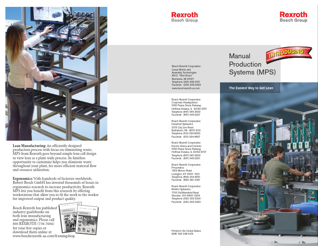
Rexroth MPS addresses lean principles through 3 completely configurable product groups: Material Transfer, Material Supply, and Ergonomic Workstations.
Lean Manufacturing: An efficiently designed production process with focus on eliminating waste. MPS from Rexroth goes beyond simple lean cell design to view lean as a plant wide process. Its limitless opportunity to customize helps you eliminate waste throughout your plant, for more efficient material flow and resource utilization.
博世力士乐REXROTH公司注册总部位于德国斯图加特而营

博世力士乐REXROTH公司注册总部位于德国斯图加特,而营运总部及董事局总办事处则设于德国洛尔,博世力士乐公司不断致力在各制造技术领域犮展,提供工业液压, 电子传动与控制, 线性传动与组装技术, 气动, 液压传动服务以及行走机械液压方面的传动与控制解决方案,最近50年来, 博世力士乐REXROTH在国际液压市埸一直处于世界领先的位置。
巴菲特自动化设备有限公司能为您提供:博世力士乐REXROTH电磁阀,截止阀,方向阀,伺服阀,溢流阀,流量控制阀,比例方向阀,比例流量控制阀,比例压力控制阀,比例放大器,柱塞泵等,大量有现货,价格实惠,是很多经销商和用户的忠实的合作伙伴。
真诚期待与您一起共创新的蓝天。
1:REXROTH 比例放大器R900214081VT-VSPA2-50-10/T1产品:2:REXROTH 比例放大器R900214081VT-VSPA2-50-10/T1技术参数:3:我公司为您提供REXROTH产品如下:VT-VSPA2-50-1X/T1 A4VG250EP4D1/32L-NTD10F721DP 08114050760811404036 DBW10B2-5X/315U6EG24NK4 A10VSO10DR/52R-PPA14N00 4WE10E33/CG24N9K4 DBW10B2-5X/315U6EG24N9K4 0811404061A10VSO71DFR1/32R-VPB22UPPS2184 4WE6J70/HG24N9K4/B10 0811405061HED8OH-2X/100K14S R90109537 4WE6G62/EW230N9K44WE6H62/EG24N9K40811404035 ZDB6VP2-4X/315V 0811405143A10VS028DFR/31R-PPA12N00 4WE6U70/HG24N9K4 A10VSO140DRS/32R-VPB22U99 3DREP6C-14/25A24NK4M 4WE10J33/CG24N9K4 DBW10B2-5X/315-6EG24N9K4 0811404037 ZDB6VP2-4X/315V A10VS028DFR/31R-PPA12N00 0811104103 4WE6D62/OFEW110N9K4 4WE6D7X/HG24N9K4A10VSO18DFR/31R-PPA12NOO 4WE6D62/EW110N9K4 A10VS0140DR/31R-PPB12N00 0811404405 A10VS045DR/31R-VPA12N00 Z2FS6-2-4X/2QV2FRM6B76-3X/1.5QMV 4WEH16E42-7X/6EG24N9EK4/B10 ZDR6DP2-43/210YM 0811405126 4WEH10E4X/6EG24N9ETK4 Z2S6A1-6XZDR6DP2-4X/75YM DB30-2N-5X/200 4WREE6E32-2X/G24K31/F1VM-3SED6CK13/350CG24N9K4 M-3SED10UK13/350CG24N9K4 4WE6D-6X/EG24N9K4 0811405060 4WE6C6X/EW230N9K4+Z5L VT3002-2X/48F 0811404039 4WEH16J7X/6EW230N9ETK4/B10+Z5L VT-VRRA 1-537-10/V0/PV 0811404601 4WEH6J7X/6EW230N9K4/B10+Z5L A10VSO18DFR/31R-PPA12NOO Z2FS6-2-4X/2QV R900481624 Z2S16-1-5X 4WE10J33/CG24N9K4HED8OH-2X/200K14 R901099808 3WE6A6X/EG24N9K4 M-3SEW6C3X/420MG24N9K4 0811402614 4WE6E62/EG24N9K4 DBDS10P18/315 0811405063 SV10PB1-4X Z2FS10-5-33/V 0811404034 DBEME10-51/200YG24MK31M 08114051260811402003 DBEME30-37/200YG24MK31M A2FO200/63L-PBB054WE6H62/EG24N9K4 4WRAE10E60-22/G24N9K31/A1V 4WREE6E16-2X/G24K31/A1V 0811405143 4WE6C62/EG24N9K4 DBE6-11/315G24K4M 0811404602 4WE6D62/EG24N9K4 3WE10B33/CG24N9K4 0811402017 4WE6J62/EG24N9K4 0811405060PV7-17/10-14RE01MCO-16 PV7-17/16-20RE01MC0-16 0811404039VT-VSPA2-50-1X/T1 PV7-17/10-14RE01MCO-16 0811404602。
Rexroth德国力士乐A4VSO型变量泵力士乐泵

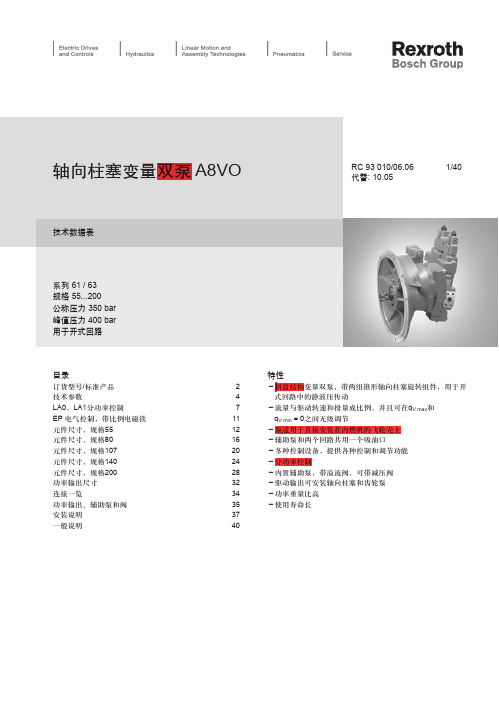
Rexroth德国力士乐A4VSO型变量泵力士乐泵A4VSO型斜盘结构轴向柱塞变量泵,专为开式回路液压驱动设计的。
泵的流量正比于泵的转速和排量,调节它的斜盘倾角可进行排量的无级调节。
位置控制斜盘结构·无级变量·优良的吸入特性·允许额定工作压力可达350 bar·低噪声·长寿命·驱动轴能承受轴向及径向负载·优良的功率/重量比·模块化设计·控制响应时间短通轴结构,可形成组合泵有斜盘角度指示器安装位置可选可用HF液体工作,但运行参数有所降低贾艳红电话:************189****1136传真:************QQ:731748437 724530971 (价格电议)型号:A4VG125HD9MT1+A11VO60LRDS+A10VO28DR+AZPFA4VTG71HW/32R-NLD10F001SA4VG90EP2DM1/32R-NAF02F731D *G*A4VTG90HW/32R-NLD10F001SA4VG125HWD1/32L-NZF02F001SA4VG125HWDL1/32R-NAF02F071D-S *SV*A4VG125HD/32+A10VO28DR/31-K *AL*A4VG180DA2D2/32R-NZD02F691LHA4VG125DA2D2/32L-NZF02F001DHA4VG125DA2D2/32L-NZF02F041SHA4VG125HW/32+A4VG71EZ/32-K *SV*A4VG56EZ2DM1/32L-NSC02F003FHA4VG71EZ2DM1/32R-NSF02F011FH *SV*A4VG56HWDL1/32R-NAC02F075D-SA4VG56EZ2DM1/32R-NSC02F023SH-K *SV*A4VG90HWDL1/32R-NAF02F071F-S *SV*A4VG90HW/32+A4VG71EZ2/32 *SV*A4VG125HD/32+A10VO28DR/31-K *AL*A4VG90HWDL1/32L-NZF02F001S-SA4VG125DA2D2/32R-NAF02F021DTA4VG180HD1DT1/32R-NZD02F01XS-SK *AL*A4VG56EZ2DM1/32R-NSC02F003FHA4VTG71HW/32R-NSD10F021SA4VG71EP2D1/32L-NAF02K021ET-S *SV*A4VG71EP2D1/32L-NAF02K021ET *SV* A4VG180HD1/32+A10VO28DR/31-SK *AL* A4VG125DA2/32+A11VO95LRDS/10A4VG180DA2/32+A11VO145LRDS/11A4VG125EP2/32+A11VO95LR/10+A11VO60LR*AL* A4VG71HWDL1/32R-NAF02F071D-SA4VG28EP4D1/32L-NSC10F003STA4VG28EP4D1/32L-NSC10F004STA4VG28EP4D1/32L-NSC10F005STA4VG28HD3D1/32R-NZC10F005SA4VG40EP4DM1/32R-NZC02F003DHA4VG40EP4/32+A4VG28EP4/32 *SV* A4VG40EP4/32+A4VG40EP4/32 *SV* A4VG56EP4DM1/32R-NZC02F003DH *SV* A4VG56EP4D1/32L-NAC02F045FH *SV* A4VG56EP4DT1/32R-NAC02F01XSH-S *SV* A4VG71EP4D2/32L-NAF02F021ST *SV* A4VG71EP4D1/32L-NAF02F021FHA4VG71HD3D2/32R-NAF02F021DA4VG71HD3DT1/32R-NAF02F01XS-SA4VG56HW/32+A4VG40EP4/32A4VG56EP4/32+A4VG40EP4/32-K *SV* A4VG56EP4/32+A10VG45EP4/10A4VG90EP0/32+A10VO28DR/31 *SV* A4VG140DA2D2/32R-NAF02F691DHA4VG71HW/32+A10VG45EZ2/10-KA4VG250EP2DT1/32R-NZD10F011SH-K *AL* A4VG56HWDL1/32R-NAC02F075F-S *SV* A4VG180DA2/32+A11VO145LRDS/11A4VG125DA2D2/32L-NAF02F021DT *AL* A4VG180DA2D2/32L-NSD02F001DTA4VG140EP2D1/32R-NAF02F021DP *AL* A4VG90EP4DT1/32R-NSF02F071SH-SA4VG90HD3DT1/32R-NSF02F011S-KA4VG71EP4/32+A4VG71EP4/32 *SV* A4VG90DA2D2/32R-NAF02F021PP-K *SV* A4VG125HD3DM1/32L-NZF02F73XF-S *SV* A4VG125HD3DT1/32L-NZF02F001DA4VG125HD3D2/32R-NTF02F691PA4VG125HD3D2/32R-NSF02F021PA4VG125EP4/32+A11VO145LR/11+A10VO28DR/31 A4VG125EP4/32+A4VG125EP4/32A4VG125EP4/32+A10VO28DRG/31-KA4VG125EP4D1/32R-NAF02F011DP-KA4VG125HD3DT1/32R-NSF02F011S-KA4VG125EP4/32+A4VG90EP4/32A4VG90EP4DT1/32R-NAF02F011SHA4VG250EP2DM1/32R-NZD10K02XEH-S *AL* A4VG125EP/32+A4VG125EP/32+A10VO28DRA4VG250EP2DM1/32L-NZD10N003EH-S *AL* A4VG71EP4D1/32L-NSF10F001DT-S *SV*A4VG250EP4D1/32R-NZD10F071DHA4VG250EP4D1/32L-NTD10F721DHA4VG250EP4/32+A11VLO190LRDS/11A4VG250EP4DT1/32R-NZD10F011SH-KA4VG250EP4DM1/32R-NZD10K02XEH-SA4VG250EP4DM1/32L-NZD10N003EH-SA4VG71DA/32+A10VO63DRS/53 *SV* A4VG125EP4D1/32R-NSF02F001KPA4VG125HD3D2/32L-NZF02F041P-SA4VG180EP4DT2/32L-NZD02F021DTA4VG180EP0/32+A10VO28DR/31A4VG180EP4DT1/32L-NZD02N001EH-SA4VG71EP4/32+A10VO45DRG/31-KA4VTG090HW100/33MLNC4C92F0000AS-0 BEIJ-0 A4VTG071HW100/33MRNC4C82F0000AS-0 BEIJ-0 A4VTG071HW100/33MLNC4C82F0000AS-0 BEIJ-0 A4VG180EP4DT1/32R-NZD02F01XSH-SA4VG180EP4/32+A4VG180EP4/32A4VG180EP4/32+A10VO45DRG/31-KA4VG180EP4DM1/32L-NZD02K02XEH-SA4VG40EP4DT1/32R-NZC02F01XSH-SA4VG125EP4+A11VO75DRS+A10VO28DRGA4VG250EP4/32+A10VO45DRG/31-KA4VG125EP4/32+A11VO75DRS/10+A10VO45DRG A4VG125HD/32+A4VG125HD/32+A10VO28DR/31-K A4VG125EP4/32+A4VG71EP4+A10VO45DRG/31-K A4VG180DWD/32+A4VG180DWD/32A4VG125EP4/32+A4VG125EP4/32A4VG125EP4DT1/32L-NZF02F011STA4VG28EP4DMT1/32R-NSC10F015DH-KA4VG125EP0/32+A10VO28DR/31 *SV* A4VG180EP0/32+A10VO28DR/31-SKA4VG180HD/32+A4VG180HD+A10VO28DR/31-KA4VG250EP4/32+A4VG250EP4/32A4VG250EP4/32+A4VG180EP4/32A4VG250EP+A4VG180EP+A10VO45+A10VO45A4VG250EP4+A11VO75DRG+A11VO75DR/10A4VG180HD/32+A4VG125HD/32+A10VO28DR/31-KA4VG28EP4/32+A4VG28DG/32A4VG180EP4/32+A11VO130LRDS/10A4VG180HD3DT1/32L-NZD02F001LA4VG180EP4D1/32L+A11VO145DRS/11LA4VG250EP4/32+A11VO40DRG/10A4VG125HD3DT1/32R-NAF02F071K-SA4VG125HD3DT1/32R-NAF02F011K-SA4VSO250DR/30R+A4VSO71DR/10RA4VSO180DFR1/30R+A10VSO71DR/31RA4VG28EP4DT1/32R-NZC10F01XST-SA4VSO40DR10RVPB13N00A4VS0250DFR/30R-PPB13N00A4V180DFR1/31R-VPA12N00A4VSO125DR/22R-PPB13N00A4VSO/71DR/10R-PPB/13N00A4VG90HDIDTI/32L-NZF021LA4VSO125DR/30R-PPB13N00A4VS040DR/10R-PB13N00NA4VSG180EO/22-LPPB10K340F+A4VSG180EO/22-LPPB10N000FA8V0107LA1KS/63R1-N2G05F074+A4VG71DWDM1/32R-NSC02F013P+A2PFF-1X-016/014 RA4VSO180DRG/30R-PPB13N00R902119803A8V0107LA1KS/63R1-N2G05F074+A4VG71DWDM1/32R-NSCO2F013P+A2PFF-1X-016/014 RA4VSO125DRA4VSO180DR/30R-PPB13N00A4VSO180DR/22R-PPB13N00A4VSO180DR/22R-PPB13N00A4VSO180DR/30R-PPB13N00A4VSG180DRA4VS071DR/30R-PPB13N00A4VSO180DR/22R-PPB13N00A4VSO250-LR2H/30R-PPB13NOOE-A4VSO125DRPPB13N00E-A4VSO180DR/30R-PPB/13N00A4VSO250-LR2G/30R-PPB13NOOA4VSO180-LR2G/30R-PPB13NOOA4VSO250LR3N-(2X)A4VSO71LR/A (075071)A4VSO180LR2G/30R-PPB13N00A4VG90HD1D7/32NZF02F021LA4VS0250DR/30R-PPB13N00A4VSO250DR/30R- PPB13N00A4VS0250E02/30R-PPB13N00A4VSO250DR/30R-PPB13N00A4VSO250DR/30R-PPB13N00(R910974769)A4VS0125E01K/11R-VZB13K34+A4VS0125E01K/11R-VZB13K01 A4VS0125E01K/11RV13N00A4VS0250DRG/30R-PPB13N00A4VSO180DR/22RPPB13NOOA4VS040DR/10R-PPB13N00A4VSO71DR/10R-PPB13N00A4VSO250E01/30R-PPB13N00-S0368+VT5035-1XA4VS0180DFE1/30R-PPB13N00A4VSO-125LR2H/10R-PPB13A4VSO-250LR2H/10R-PPB13A4VSO180DR/30R-PPB13N00A4VG56EP2DM1/32RNZC02F003DHE-A4VS0180DR/30R-PPB13NOOA4VSO71LR2D/12R-PPB13N00A4VG56EP2DM1/32RNZC02F003DHA4VSO125DR/30R-PPB13N00A4VS0250DR/30R-PPB13N00A4VS0180DR/30R-PPB13N00A4VS0180DFE1/30R-PPB13N00A4VSO250LR2/30R-PPB13N00E-A4VS0125DR/30R-PPB13N00E-A4VS0125DR/30R-PPB13N00A4VS0125DR/30R-PPB13N00E-A4VSO125DR/30R-PPB13N00E-A4VSO250DR/30R-PPB13N00A4VSO250DR/30R-PPB13N00A4VSO125LR2/30R-PPB13N00A4VSO500HSE/20R-PPH13N00A4VSO125HSE/20R-PPH13N00A4VSO71LR2D/20R-PPB1300A4VSO180DR/30R-PPB13NOOA4VSO125DR/22R-PPB13ND0A4VS040DR/10RPPB13N00A4VSO180DR/30R-PPB13N00A4VSO180LR2G/30R-PPB13NOOA4VSO250LR2G/30R-PPB13NOOE-A4VSO180DR/30R-PPB13N00E-A4VSO180DR/30R-PPB13N00E-A4VSO180DR/30RPPB13N00E-A4VSO180DR/30R-PPB13N00A4VSO250E02/30R-VPB25N00-S0368A4VS0125HDIT/30RPPB13N00A4VS0125HDIT/30RPPB13N00A4VS0125DR/30RPPB13N00A4VSO250HD/11R-PPB13K25-S0166升级为以下型号A4VSO250HD/30R-PPB13K25-S0166 A4VSO180HS4/30R-PPB13N00A4VSO180HS4/30R-PPB13N00A4VSO71DR/10R-PPB13N00A4VSO71DR/10R-PPB13N00A4VSO180DR/30R-PPB13N00A4VSO180DR/30R-PPB13N00A4VSO125DR/30R-PPB12NOOA4VSO125DR/30R-PPB12NOO。
力士乐A8VO变量泵(个人苦心详解版)
A8V
O
55 80 107 140 200 55 80 107 140 200
●
❍
l
❍
❍ LA0H2
–
–
❍
❍
❍ LA0S
l
l
l
❍
– LA0K
–
❍
❍
l
❍ LA0KS
❍
❍
❍
❍
❍ LA0KH1
l
l
l
l
l LA0KH2
❍
❍
l
l
l LA0KH3
l
l
l
l
l LA1H2
–
–
l
l
l LA1S
❍
❍
❍
❍
– LA1K
–
❍
订货时请用文字说明所使用的液压油。
粘度范围
为获得最优效率和使用寿命,我们推荐工作粘度(在工作温度 时)在下列范围内选择:
νopt = 最佳粘度 16...36 mm2/s
开式回路中针对油箱温度。
粘度极限范围
极限粘度值如下: νmin = 5 mm2/s 短时 (t < 3 min) ,最高允许温度tmax = +115°C下。 νmax = 1600mm2/s, 短时(t < 3 min) ,冷启动(p < 30 bar, n ≤ 1000 rpm, tmin = -40°C)下。 请注意,最高允许油液温度115°C即使在局部也不可超过 (如轴承区)。轴承区的温度与压力和转速有关,它比平均 壳体泄油温度高12K。 温度在-40°C和-25°C之间时,需要采取特殊措施。请与我 公司联系。 有关在低温下使用的详细资料,参见RC 90300-03-B。
港版_力士乐(rexroth)滑块产品的资料

Taille 25
Crémaillère Référence R2050 213 02
Longueur 1200
R2050 214 02
600
Pignon
Référence
Exécution
R2051 253 01
Dents = 20
Collerette d = 24
R2051 254 01
Dents = 25 Collerette d = 24
Techniques de translation
Guidages à billes sur rails
Guidages sur rails standard Guidages sur rails Super Guidages sur rails avec guide en aluminium Guidages sur rails pour vitesses élevées Guidages sur rails résistant à la corrosion Guidages sur rails larges
– avec entraînement par vis à billes – avec entraînement par courroie crantée – avec entraînement par crémaillère – avec entraînement pneumatique – avec entraînement par moteur linéaire
1 3
2
1 3
2
1
3
2
R310FR 2217 (2005.01) GBR – Crémaillère Linear Motion and Assembly Technologies Bosch Rexroth AG
- 1、下载文档前请自行甄别文档内容的完整性,平台不提供额外的编辑、内容补充、找答案等附加服务。
- 2、"仅部分预览"的文档,不可在线预览部分如存在完整性等问题,可反馈申请退款(可完整预览的文档不适用该条件!)。
- 3、如文档侵犯您的权益,请联系客服反馈,我们会尽快为您处理(人工客服工作时间:9:00-18:30)。
工业液压元件(第一册)液压阀、动力单元、滤油器及蓄能器
P1~P276
第0节(一般资料)
第一节(截止阀)
第二节(方向阀)
工业液压元件(第一册)液压阀、动力单元、滤油器及蓄能器
P277~P450
第二节(方向阀)
第三节(溢流阀)
工业液压元件(第一册)
液压阀、动力单元、滤油器及蓄能器
P451~P648
第四节(减压阀)
第五节(顺序阀)
第六节(流量控制阀)
工业液压元件(第一册)
液压阀、动力单元、滤油器及蓄能器
P649~P828
第七节(二通插装阀<逻辑单元>)
工业液压元件(第一册)
液压阀、动力单元、滤油器及蓄能器
P829~P966
第八节(控制块/板)
工业液压元件(第一册)
液压阀、动力单元、滤油器及蓄能器
P967~P1156
第九节(压力显示器和压力开关)第十节(滤油器)
第十一节(蓄能器和蓄能器附件)
工业液压元件(第一册)
液压阀、动力单元、滤油器及蓄能器
P1157~P1376
第十二节(液压动力单元和附件)工业液压元件(第三册)液压泵/马达及液压缸
P1~P288
第0节(一般资料)
第一节(轴向柱塞单元)
工业液压元件(第三册)液压泵/马达及液压缸P289~P490
第一节(轴向柱塞单元)
第二节(轴向柱塞单元用的电子附件)
工业液压元件(第三册)液压泵/马达及液压缸P493~P778
第二节(轴向柱塞单元用的电子附件)
第三节(齿轮泵、叶片泵及径向柱塞泵)
第四节(柱塞式马达)
工业液压元件(第三册)液压泵/马达及液压缸P779~P986
第四节(柱塞式马达)
第五节(行星马达<定位马达>)
第六节(径向柱塞式偏心马达)
第七节(泵/马达总成)
工业液压元件(第三册)液压泵/马达及液压缸P987~P1182
第八节(液压缸)。