英文翻译原文
英语文摘中英对照File

英语文摘中英对照File一、生活感悟英文原文:Life is like a camera. Just focus on what's important and capture the good times, develop from the negatives and if things don't work out, just take another shot.中文翻译:生活就像一台相机。
只需关注重要的事物,捕捉美好时光,从挫折中成长,如果事情不尽如人意,那就再试一次。
二、名人名言英文原文:"The only way to do great work is to love what you do." – Steve Jobs中文翻译:“成就伟大事业的唯一途径,就是热爱你所做的事。
” ——史蒂夫·乔布斯三、趣味故事英文原文:Once upon a time, there was a fox who was very proud of his tail. One day, he got caught in a trap and had to sacrifice his tail to escape. Though he was free, he felt ashamed of his appearance. However, he soon realized that his life was more important than his tail.中文翻译:从前,有一只狐狸非常自豪自己的尾巴。
有一天,它不慎陷入了陷阱,为了逃脱,不得不牺牲自己的尾巴。
虽然它重获自由,但它为自己的外貌感到羞愧。
然而,它很快意识到,生命比尾巴更重要。
四、励志故事英文原文:Thomas Edison failed more than 10,000 times before he invented the light bulb. When asked about his failures, he replied, "I have not failed. I've just found 10,000 ways that won't work."中文翻译:托马斯·爱迪生在发明电灯泡之前失败了超过一万次。
英文原文及翻译

Vera Wang Honors Her Chinese Roots王薇薇以中国根为傲With nuptials(婚礼) season in full swing, Vera Wang’s wedding dress remains at the top of many a bride’s(婚礼) wish list. The designer, who recently took home the lifetime achievement award from the Council of Fashion Designers of America, has been innovating in bridal design for years—using color, knits and even throwing fabric into a washing machine.随着婚礼季的全面展开,王薇薇(Vera Wang)婚纱依然是许多新娘愿望清单上的首选。
王薇薇最近刚拿到美国时装设计师协会(Council of Fashion Designers of America)颁发的终生成就奖。
多年来她一直在婚纱设计领域进行创新──运用色彩和编织手法,甚至将面料扔进洗衣机里。
Ms. Wang said that her latest collection is about construction. “I had felt that I had really messed that vocabulary of perfection for brides for a while, where there’s six fabrics to a skirt, ” she said. “I wanted to go back to something that maybe was what I started with, but in a whole new way, and that would be architecture—not simplicity—but maybe minimalism.”王薇薇说,她的最新婚纱系列重点在于构建。
名篇名译(英译汉)

名篇名译0011.原文:It is an ill wind that blows nobodygood.译文:世事皆利弊并存。
赏析:原句结构比较特殊("Itis…that…"),理解起来有点困难。
“对谁都没有好处的风才是坏风”,也就是说大多数情况下风对人都是有好处、有坏处,在引申一步就是成了上面的译句。
林佩耵在《中英对译技巧》一书中(第68页)还给了几个相同结构的英文句子。
翻译的前提是理解。
有人指出。
市面上见到的翻译作品,有好多都带有因理解不正确而产生的低级错误,“信”都谈不上还妄谈什么“达”和“雅”!初学翻译的朋友,在理解原文上当不遗余力。
2.原文:Their languag e was almostunrestr ainedby any motiveof prudenc e.译文:他们几乎爱讲什么就讲什么,全然不考虑什么谨慎不谨慎。
赏析:如果硬译,译文势必成了“他们的言论几乎不受任何深思熟虑的动机的约束”。
译者本其译,化其滞,将原句一拆为二,充分运用相关翻译技巧,译文忠实、通顺。
3.原文:Get a livelih ood,and then practis e virtue.译文:先谋生而后修身。
(钱钟书译)赏析:原句是祈使句,译句也传达出了训导的意味。
用“谋生”来译“Getalivelih ood",用“修身”来译“practis e virtue",可谓精当。
巧的是,原句七个词,译句也是七个汉字。
4.原文:I enjoy the clean voluptu ousnes s of the warm breezeon my skin and the cool support of water.译文:我喜爱那洁净的暖风吹拂在我的皮肤上使我陶然欲醉,也喜爱那清亮的流水把我的身体托浮在水面。
中英文翻译英文原文
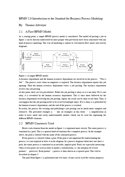
BPMN 2.0 Introduction to the Standard for Business Process Modeling By Thomas Allweyer2.1 A First BPMN ModelAs a starting point, a simple BPMN process model is considered. The model of posting a job in figure 1 can be directly understood by most people who previously have been concerned with any kind of process modeling. The way of modeling is similar to well known flow charts and activity diagrams.Figure 1: A simple BPMN modelA business department and the human resources department are involved in the process “Post a Job”. The process starts when an employee is required. The business department reports this job opening. Then the human resources department writes a job posting. The business department reviews this job posting.At this point, there are two possibilities: Either the job posting is okay, or it is not okay. If it is not okay, it is reworked by the human resources department. This is once more followed by the business department reviewing the job posting. Again, the result can be okay or not okay. Thus, it can happen that the job posting needs to be reviewed multiple times. If it is okay, it is published by the human resources department, and the end of the process is reached.In reality, the process for creating and publishing a job posting can be much more complex and extensive. The presented example is –like all examples in this book –a simplification in order to have small and easily understandable models which can be used for explaining the different BPMN elements.2.2 BPMN Constructs UsedBelow each element from the model in figure 1 is explained more closely. The entire process is contained in a pool. This is a general kind of container for a complete process. In the example above, the pool is labeled with the name of the contained process.Every process is situated within a pool. If the pool is not important for understanding the process, it is not required to draw it in the diagram. In a process diagram which does not show a pool, the entire process is contained in an invisible, implicit pool. Pools are especially interesting when several pools are used in order to model a collaboration, i.e. the interplay of several partners’processes. Each partner’s process is then shown in a separate pool. This will be described in chapter 5.The pool from figure 1 is partitioned into two lanes. A lane can be used for various purposes,e.g. for assigning organizational units, as in the example, or for representing different components within a technical system. In the example, the lanes show witch of the process’s activities are performed by the business department and which by the human resource department.Pools and lanes are also called “swimlanes”. They resemble the partitioning of swimming pools into lanes. Every participant of a competition swims only in his own lane.The process itself begins with the start event “Employee required”. Processes usually have such a start event. Its symbol is a simple circle. In most cases it makes sense to use only one start event, not several ones.A rounded rectangle represents an activity. In an activity something gets done. This is expressed by the activities’names, such as “Report Job Opening”or “Review Job Posting”.The connecting arrows are used for modeling the sequence flow. They represent the sequence in which the different events, activities, and further elements are traversed. Often this is called control flow, but in BPMN there is a second type of flow, the message flow, which influences the control of a process as well, and is therefore some kind of control flow, too. For that reason, the term “sequence flow”is used. For distinguishing it from other kinds of flow, it is important to draw sequence flows with solid lines and filled arrowheads.The process “Post a Job”contains a split: The activity “Review job posting”is followed by a gateway. A blank diamond shape stands for an exclusive gateway. This means that out of several outgoing sequence flows, exactly one must be selected. Every time the right gateway in the job posting-process is reached, a decision must be taken. Either the sequence flow to the right is followed, leading to the activity “Publish Job Posting”, or the one to the left is selected, triggering the activity “Rework Job Posting”. It is not possible to follow both paths simultaneously.The logic of such a decision is also called “exclusive OR”, abbreviated “XOR”. The conditions on the outgoing paths determine which path is selected. If a modeling tool is used and the process has to be executed or simulated by a software program, then it is usually possible to formally define exact conditions. Such formal descriptions, which may be expressed in a programming language, can be stored in special attributes of the sequence flows.If, on the other hand, the purpose of a model is to explain a process to other people,then it is advisable to write informal, but understandable, statements directly into the diagram, next to the sequence flows. The meaning of “okay”and “not okay”after the activity called “Review Job Posting”is clear to humans –a program could not make use of it.Gateways are also used for merging alternative paths. In the sample process, the gateway on the left of the activity “Review Job Posting”merges the two incoming sequence flows. Again, this is an exclusive gateway. It expects that either the activity“Write Job Posting”or “Rework Job Posting”is carried out before the gateway is reached –but not both at the same time. It should be taken care to use a gateway either for splitting or for joining, but not for a combination of both. The last element in the example process is the end event. Like the start event it has a circle as symbol –but with a thick border.2.3 Sequence Flow LogicThe flow logic of the job posting process above is rather easy to understand. In more complex models it is sometimes not clear how the modeled structure exactly is to be interpreted. Therefore it is helpful if the meaning of the sequence flow’s elements is defined in an unambiguous way.The logic of a process diagram’s sequence flow can be explained by “tokens”. Just as in a board game tokens are moved over the board according to the game’s rules, one can imagine moving tokens through a process model according to BPMN’s rules.Every time the process is started, the start event creates a token (cf. figure 2). Since the job posting process is carried out more than once, many tokens can be created in the course of time. Thereby it can happen that the process for one job posting is not yet finished, when the process for posting another job starts. As it moves through the process, each token is independent from the other tokens’movements.Figure 2: A start event creates a tokenThe token that has been created by the start event moves through the sequence flow to the first activity. This activity receives a token, performs its task (in this case it reports a job opening), and then releases it to the outgoing sequence flow (cf. figure 3).Figure 3: An activity receives a token and forwards it after completionThe following activity forwards the token. It then arrives at the merging exclusive gateway. The task of this gateway is simple: It just takes a token that arrives via any incoming sequence flow and moves it to the outgoing sequence flow. This is shown in figure 4. In case A, a token arrives from the left, in case B from below. In both cases the token is routed to the outgoing sequence flow to the right.Figure 4: Routing of a token by a merging exclusive gatewayThe task of the splitting exclusive gateway is more interesting. It takes one arriving token and decides according to the conditions, to which sequence flow it should be moved. In case A in figure 5, the condition “okay”is true, i.e. the preceding review activity has produced a positive result. In this case, the token is moved to the right. Otherwise, if the condition “not okay”is true, the token is moved to the downwards sequence flow (case B).The modeler must define the conditions in such a way that always exactly one of the conditions is true. The BPMN specification does not state how to define conditions and how to check whichconditions are true. Since the considered process is not executed by software, the rather simple statements used here are sufficient. Otherwise, it would be necessary to define the conditions according to the requirements and rules of the software tool.The token may travel several times through the loop for reworking the job posting. Finally it arrives at the end event. This simply removes any arriving token and thus finishes the entire process (figure 6).Figure 5: Routing of a token by a splitting exclusive gatewayThe sequence flow of every process diagram can be simulated in this way with the help of tokens. This allows for analyzing whether the flow logic of a process has been modeled correctly.It should be noted that a token does not represent such a thing as a data object or a document. In the case of the job posting process, it could be imagined to have a document “job posting”flowing through the process. This document could contain all required data, such as the result of the activity “Review Job Posting”. At the splitting gateway, the decision could then be based on this attribute value. However, the BPMN sequence flow is constrained to the pure order of execution. The tokens therefore do not carry any information, other than a unique identifier for distinguishing the tokens from each other. For data objects there are separate BPMN constructs which will be presented in chapter 10.2.4 Presentation OptionsUsually pools are drawn horizontally. The preferred direction of sequence flow is then from left to right. On the other hand, it is also possible to use vertical pools and to draw the sequence flow from top to bottom, as in the example in figure 7.It makes sense to decide for only one of these possibilities –horizontal or vertical. Nevertheless there are modeling tools which only support horizontal modelingFigure 6: An end event removes an arriving tokenFigure 7: Vertical swimlanes and nested lanesFigure 7 also shows an example of nested lanes. The lane labeled “Sales”is partitioned into the two lanes “Sales Force”and “Order Processing”. In principle it is possible to partition these lanes again, etc., although this only makes sense up to a certain level of depth.It is not prescribed where to place the names of pools and lanes. Typical are the variants selected for figure 1 and figure 7. Here the names are placed on the left of the pools or lanes, or at the top for the vertical style, respectively. The name of a pool is separated by a line. The names of the lanes, however, are placed directly within the lanes. A separation line is only used for a lane that is partitioned into further sub-lanes. Lanes can also be arranged as a matrix. The procurement process in figure 8 runs through a business department and the procurement department, both of which span a branch office and the headquarters. When a demand occurs in a branch’s business department, this department reports the demand. In the next step, the procurement is approved by the same department in the headquarters. The central part of the procurement department then closes a contract with a supplier, followed by the branch’s purchasing department carrying out the purchase locally.Although the BPMN specification explicitly describes the possibility of such a matrix presentation, it is hardly ever applied, so far.12.2 Message CorrelationThe contents of the message flows within one conversation are always related to each other. For example, all messages that are exchanged within one instance of the conversation “Process Order for Advertisement”relate to the same advertisement order. It is therefore possible to use the order ID for the correlation, i.e. the assignment of messages to a process instance. If a customer receives an advertisement for approval, he can determine the corresponding order –and thus the process instance –based on the order ID. All messages of a conversation have a common correlation.A simple conversation which is not broken down into other conversations is called communication. Therefore, the lines are called communication links (the specification draft at some places alsocalls them conversation links). A conversation has always communication links to two or more participants.If the end of a communication link is forked, multiple partners of the same type can be part of the communication, otherwise exactly one. “Process Order for Advertisement”has exactly one customer and one advertising agency as participants, but multiple designers. Therefore, the designer’s pool contains a multiple marker. However, having only the multiple marker in the pool is not sufficient. The conversation “Handle order for an illustration”, for example, has only one designer as participant. Therefore, the respective end of the communication link is not forked.12.3 Hierarchies of ConversationsBesides communications, it is also possible to use sub-conversations. Similar to sub-processes they are marked with a ‘+’-sign. The details of a sub-conversation can be described in another conversation diagram. The diagram of a sub-conversation can only contain those participants who are linked to the sub-conversation within the parent diagram.Figure 171 shows the detailed conversation diagram for the sub-conversation “Process Order for Advertisement”As can be seen from this diagram, it is also possible to draw message flows directly into the conversation diagram. Other than collaboration diagrams, conversation diagrams are not allowed to show processes in the pools or choreographies between the pools.Figure 171: Conversation diagram for sub-conversation “Process Order for Advertisement”The diagram contains those message flows that are related to the same order. To be more precise, they relate to the same inquiry. At the beginning, an order has not been placed yet, and not every inquiry turns into an order. Therefore, the common reference point is the inquiry.Besides the explicitly displayed message flows between customer and advertising agency, the diagram also contains the communication “Assignment of Graphics Design”. All message flows of this communication are also related to the same inquiry, but this information is not sufficient for the advertising agency in order to assign all incoming messages correctly. This is due to the fact that availability requests are sent to several designers. The advertising agency has to correctly assign each incoming availability notice to the correct availability request. Thus, additional information is required for correlating these messages, e.g. the IDs of the availability requests.Therefore it is possible to define a separate communication for the message flows between advertising agency and designer. The message exchanges of this communication can also be modeled in a collaboration diagram (figure 172) or in a choreography diagram (figure 173). Of course, it is also possible to show the message flows of the entire sub-conversation within a single diagram (figures 161 and 162 in the previous chapter).Figure 172: Collaboration diagram for communication “Assignment of Graphics Design”Like sub-processes, sub-conversations can also be expanded, i.e. the hexagon is enlarged, and the detailed conversation is shown in its interior. However, it is graphically not easy to include, for example, the contents of figure 171 into an expanded sub-conversation in figure 170. Unfortunately, the BPMN specification draft does not contain any examples for expandedsub-conversations either.。
中英文翻译

附录英文原文:Chinese Journal of ElectronicsVo1.15,No.3,July 2006A Speaker--Independent Continuous SpeechRecognition System Using Biomimetic Pattern RecognitionWANG Shoujue and QIN Hong(Laboratory of Artificial Neural Networks,Institute ol Semiconductors,Chinese Academy Sciences,Beijing 100083,China)Abstract—In speaker-independent speech recognition,the disadvantage of the most diffused technology(HMMs,or Hidden Markov models)is not only the need of many more training samples,but also long train time requirement. This Paper describes the use of Biomimetic pattern recognition(BPR)in recognizing some mandarin continuous speech in a speaker-independent Manner. A speech database was developed for the course of study.The vocabulary of the database consists of 15 Chinese dish’s names, the length of each name is 4 Chinese words.Neural networks(NNs)based on Multi-weight neuron(MWN) model are used to train and recognize the speech sounds.The number of MWN was investigated to achieve the optimal performance of the NNs-based BPR.This system, which is based on BPR and can carry out real time recognition reaches a recognition rate of 98.14%for the first option and 99.81%for the first two options to the Persons from different provinces of China speaking common Chinese speech.Experiments were also carried on to evaluate Continuous density hidden Markov models(CDHMM ),Dynamic time warping(DTW)and BPR for speech recognition.The Experiment results show that BPR outperforms CDHMM and DTW especially in the cases of samples of a finite size.Key words—Biomimetic pattern recognition, Speech recogniton,Hidden Markov models(HMMs),Dynamic time warping(DTW).I.IntroductionThe main goal of Automatic speech recognition(ASR)is to produce a system which will recognize accurately normal human speech from any speaker.The recognition system may be classified as speaker-dependent or speaker-independent.The speaker dependence requires that the system be personally trained with the speech of the person that will be involved with its operation in order to achieve a high recognition rate.For applications on the public facilities,on the other hand,the system must be capable of recognizing the speech uttered by many different people,with different gender,age,accent,etc.,the speaker independence has many more applications,primarily in the general area of public facilities.The most diffused technology in speaker-independent speech recognition is Hidden Markov Models,the disadvantage of it is not only the need of many more training samples,but also long train time requirement.Since Biomimetic pattern recognition(BPR) was first proposed by Wang Shoujue,it has already been applied to object recognition, face identification and face recognition etc.,and achieved much better performance.With some adaptations,such modeling techniques could be easily used within speech recognition too.In this paper,a real-time mandarin speech recognition system based on BPR is proposed,which outperforms HMMs especially in the cases of samples of a finite size.The system is a small vocabulary speaker independent continuous speech recognition one. The whole system is implemented on the PC under windows98/2000/XPenvironment with CASSANN-II neurocomputer.It supports standard 16-bit sound card .II .Introduction of Biomimetic Pattern Recognition and Multi —Weights Neuron Networks1. Biomimetic pattern recognitionTraditional Pattern Recognition aims at getting the optimal classification of different classes of sample in the feature space .However, the BPR intends to find the optimal coverage of the samples of the same type. It is from the Principle of Homology —Continuity ,that is to say ,if there are two samples of the same class, the difference between them must be gradually changed . So a gradual change sequence must be exists between the two samples. In BPR theory .the construction of the sample subspace of each type of samples depends only on the type itself .More detailedly ,the construction of the subspace of a certain type of samples depends on analyzing the relations between the trained types of samples and utilizing the methods of “cov erage of objects with complicated geometrical forms in the multidimensional space”.2.Multi-weights neuron and multi-weights neuron networksA Multi-weights neuron can be described as follows :12m Y=f[(,,,)]W W W X θΦ-…,,Where :12m ,,W W W …, are m-weights vectors ;X is the inputvector ;Φis the neuron’s computation function ;θis the threshold ;f is the activation function .According to dimension theory, in the feature spacen R ,n X R ∈,the function12m (,,,)W W W X Φ…,=θconstruct a (n-1)-dimensional hypersurface in n-dimensional space which isdetermined by the weights12m ,,W W W …,.It divides the n-dimensional space into two parts .If12m (,,,)W W W X θΦ=…, is a closed hypersurface, it constructs a finite subspace .According to the principle of BPR,determination the subspace of a certain type of samples basing on the type of samples itself .If we can find out a set of multi-weights neurons(Multi-weights neuron networks) that covering all the training samples ,the subspace of the neural networks represents the sample subspace. When an unknown sample is in the subspace, it can be determined to be the same type of the training samples .Moreover ,if a new type of samples added, it is not necessary to retrain anyone of the trained types of samples .The training of a certain type of samples has nothing to do with the other ones .III .System DescriptionThe Speech recognition system is divided into two main blocks. The first one is the signal pre-processing and speech feature extraction block .The other one is the Multi-weights neuron networks, which performs the task of BPR .1.Speech feature extractionMel based Campestral Coefficients(MFCC) is used as speech features .It is calculated as follows :A /D conversion ;Endpoint detection using short time energy and Zero crossing rate(ZCR);Preemphasis and hamming windowing ;Fast Fourier transform ;DCT transform .The number of features extracted for each frame is 16,and 32 frames are chosen for every utterance .A 512-dimensiona1-Me1-Cepstral feature vector(1632⨯ numerical values) represented the pronunciation of every word . 2. Multi-weights neuron networks architectureAs a new general purpose theoretical model of pattern Recognition, here BPR is realized by multi-weights neuron Networks. In training of a certain class of samples ,an multi-weights neuron subNetwork should beestablished .The subNetwork consists of one input layer .one multi-weights neuron hidden layer and one output layer. Such a subNetwork can be considered as a mapping 512:F R R →.12m ()min(,,Y )F X Y Y =…,,Where Y i is the output of a Multi-weights neuron. There are m hiddenMulti-weights neurons .i= 1,2, …,m,512X R ∈is the input vector .IV .Training for MWN Networks1. Basics of MWN networks trainingTraining one multi-weights neuron subNetwork requires calculating the multi-weights neuron layer weights .The multi-weights neuron and the training algorithm used was that of Ref.[4].In this algorithm ,if the number of training samples of each class is N,we can use2N -neurons .In this paper ,N=30.12[(,,,)]ii i i Y f s s s x ++=,is a function with multi-vector input ,one scalar quantity output .2. Optimization methodAccording to the comments in IV.1,if there are many training samples, the neuron number will be very large thus reduce the recognition speed .In the case of learning several classes of samples, knowledge of the class membership of training samples is available. We use this information in a supervised training algorithm to reduce the network scales .When training class A ,we looked the left training samples of the other 14 classes as class B . So there are 30 training samples in set1230:{,,}A A a a a =…,and 420 training samples inset 12420:{,,}B B b b =…,b .Firstly select 3 samples from A, and we have a neuron :1123Y =f[(,,,)]k k k a a a x .Let 01_123,=f[(,,,)]A i k k k i A A Y a a a a =,where i= 1,2, (30)1_123Y =f[(,,,)]B j k k k j a a a b ,where j= 1,2,…420;1_min(Y )B j V =,we specify a value r ,0<r<1.If1_*A i Y r V <,removed i a from set A, thus we get a new set (1)A .We continue until the number ofsamples in set ()k Ais(){}k A φ=,then the training is ended, and the subNetwork of class A has a hiddenlayer of1r - neurons.V .Experiment ResultsA speech database consisting of 15 Chinese dish’s names was developed for the course of study. The length of each name is 4 Chinese words, that is to say, each sample of speech is a continuous string of 4 words, such as “yu xiang rou si”,“gong bao ji ding”,etc .It was organized into two sets :training set and test set. The speech signal is sampled at 16kHz and 16-bit resolution .Table 1.Experimental result atof different values450 utterances constitute the training set used to train the multi-weights neuron networks. The 450 ones belong to 10 speakers(5 males and 5 females) who are from different Chinese provinces. Each of the speakers uttered each of the word 3 times. The test set had a total of 539 utterances which involved another 4 speakers who uttered the 15 words arbitrarily .The tests made to evaluate the recognition system were carried out on differentr from 0.5 to 0.95 with astep increment of 0.05.The experiment results at r of different values are shown in Table 1.Obviously ,the networks was able to achieve full recognition of training set at any r .From the experiments ,it was found that0.5r achieved hardly the same recognition rate as the Basic algorithm. In the mean time, theMWNs used in the networks are much less than of the Basic algorithm. Table 2.Experiment results of BPR basic algorithmExperiments were also carried on to evaluate Continuous density hidden Markov models (CDHMM),Dynamic time warping(DTW) and Biomimetic pattern recognition(BPR) for speech recognition, emphasizing the performance of each method across decreasing amounts of training samples as wellas requirement of train time. The CDHMM system was implemented with 5 states per word.Viterbi-algorithm and Baum-Welch re-estimation are used for training and recognition .The reference templates for DTW system are the training samples themselves. Both the CDHMM and DTW technique are implemented using the programs in Ref.[11].We give in Table 2 the experiment results comparison of BPR Basic algorithm ,Dynamic time warping (DTW)and Hidden Markov models (HMMs) method .The HMMs system was based on Continuous density hidden Markov models(CDHMMs),and was implemented with 5 states per name.VI.Conclusions and AcknowledgmentsIn this paper, A mandarin continuous speech recognition system based on BPR is established.Besides,a training samples selection method is also used to reduce the networks scales. As a new general purpose theoretical model of pattern Recognition,BPR could be used in speech recognition too, and the experiment results show that it achieved a higher performance than HMM s and DTW.References[1]WangShou-jue,“Blomimetic (Topological) pattern recognit ion-A new model of pattern recognition theoryand its application”,Acta Electronics Sinica,(inChinese),Vo1.30,No.10,PP.1417-1420,2002.[2]WangShoujue,ChenXu,“Blomimetic (Topological) pattern recognition-A new model of patternrecognition theory and its app lication”, Neural Networks,2003.Proceedings of the International Joint Conference on Neural Networks,Vol.3,PP.2258-2262,July 20-24,2003.[3]WangShoujue,ZhaoXingtao,“Biomimetic pattern recognition theory and its applications”,Chinese Journalof Electronics,V0l.13,No.3,pp.373-377,2004.[4]Xu Jian.LiWeijun et a1,“Architecture research and hardware implementation on simplified neuralcomputing system for face identification”,Neuarf Networks,2003.Proceedings of the Intern atonal Joint Conference on Neural Networks,Vol.2,PP.948-952,July 20-24 2003.[5]Wang Zhihai,Mo Huayi et al,“A method of biomimetic pattern recognition for face recognition”,Neural Networks,2003.Proceedings of the International Joint Conference on Neural Networks,Vol.3,pp.2216-2221,20-24 July 2003.[6]WangShoujue,WangLiyan et a1,“A General Purpose Neuron Processor with Digital-Analog Processing”,Chinese Journal of Electornics,Vol.3,No.4,pp.73-75,1994.[7]Wang Shoujue,LiZhaozhou et a1,“Discussion on the basic mathematical models of neurons in gen eralpurpose neuro-computer”,Acta Electronics Sinica(in Chinese),Vo1.29,No.5,pp.577-580,2001.[8]WangShoujue,Wang Bainan,“Analysis and theory of high-dimension space geometry of artificial neuralnetworks”,Acta Electronics Sinica (in Chinese),Vo1.30,No.1,pp.1-4,2001.[9]WangShoujue,Xujian et a1,“Multi-camera human-face personal identiifcation system based on thebiomimetic pattern recognition”,Acta Electronics Sinica (in Chinese),Vo1.31,No.1,pp.1-3,2003.[10]Ryszard Engelking,Dimension Theory,PWN-Polish Scientiifc Publishers—Warszawa,1978.[11]QiangHe,YingHe,Matlab Porgramming,Tsinghua University Press,2002.中文翻译:电子学报2006年7月15卷第3期基于仿生模式识别的非特定人连续语音识别系统王守觉秦虹(中国,北京100083,中科院半导体研究所人工神经网络实验室)摘要:在非特定人语音识别中,隐马尔科夫模型(HMMs)是使用最多的技术,但是它的不足之处在于:不仅需要更多的训练样本,而且训练的时间也很长。
人教版高中英语课文原文与翻译参考

⼈教版⾼中英语课⽂原⽂与翻译参考⼈教版⾼中英语课⽂原⽂与翻译参考 ⾼中英⽂课⽂⼀《⼈教版⾼中英语课⽂原⽂和翻译》 ANNE’S BEST FRIEND Do you want a friend whom you could tell everything to, like your deepest feelings and thoughts? Or are you afraid that your friend would laugh at you, or would not understand what you are going through? Anne Frank wanted the first kind, so she made her diary her best friend. 安妮最好的朋友 你想不想有⼀位⽆话不谈能推⼼置腹的朋友?或者你会不会担⼼你的朋友会嘲笑你,会不理解你⽬前的困境呢?安妮?弗兰克想要的是第⼀种类型的朋友,所以她把的⽇记视为⾃⼰最好的朋友。
Anne lived in Amsterdam in the Netherlands during World War II. Her family was Jewish so the had to hide or they would be caught by the German Nazis. She and her family hide away for two years before they were discovered. During that time the only true friend was her diary. She said, “I don’t want to set down a series of facts in a diary as most people do, but I want this diary itself to be my friend, and I shall call my friend Kitty.” Now read how she felt after being in the hiding place since July 1942. 在第⼆次世界⼤战期间,安妮住在荷兰的阿姆斯特丹。
牛津英语必修一课文原文及中文翻译

M1U1S C H O O L l i f e i n t h e U KGoing to a British high school for one year was a very enjoyable and exciting experience for me. I was very happy with the school hours in Britain because school starts around 9 a later than usual as schools in China begin before 8 a.m.On the first day, all of the new students attended an assembly in the school hall. I sat next to a girl whose name is Diane. We soon became best friends. During the assembly, the headmaster told us about the rules of the school. He also told us that the best way to earn respect was to devote oneself to study and achieve high grades. This sounded like my school in China.I had many teachers in the past year. Mr. Heywood , my class teacher, was very helpful. My favorite teacher was Miss Burke—I loved the lessons that she gave in English Literature. In our class there were 28 students. This is about the average size for British schools. We had to move to different classrooms for different classes. We also had different students in some classes, so it was a struggle for me to remember all the faces and names.I found the homework was not as heavy as what I used to get in my old school, but it was a bit challenging for me at firs t because all the homework was in English. I felt lucky as all my teachers gave me much encouragement and I enjoyed all my subjects: English, History, English Literature, Computer Science, Maths, Science, PE, Art, Cooking and French.My English improved a lot as I used English every day and spent an hour each day reading English books in the library.I usually went to the Computer Club during the lunch break, so I could send e-mails to my family and friends back home for free. I also had an extra French class on Tuesday evenings. Cooking was really fun as I learned how to buy, prepare and cook food. At the end of term we held a class party and we all had to cook something. I was glad that all my classmates were fond of the cake that I made.Students at that school have to study Maths, English and Science, but can stop studying some subjects if they don’t like them, for example, History and French. They can choose other subjects like Art and Computer Science or Languages such as Spanish and German. In the Art class that I took, I made a small sculpture. Though it didn’t look very beautiful when it was finished, I still liked it very much.I missed Chinese food a lot at lunch. British food is very different. British people like eating dessert at the end of their main meal. After lunch, we usually played on the school field. Sometimes I played football with the boys. Sometimes I just relaxed under a tree or sat on the grass.I was very lucky to experience this different way of life. I look back on my time in the UK with satisfaction, and I really hope to go back and study in Manchester again.在英国的学校生活在英国上了一年的中学对我来说是一段非常令人愉快和兴奋的经历。
朱自清荷塘月色英文版

朱自清《荷塘月色》英文版著名作家朱自清的散文《荷塘月色》想必大家已经在语文课上学过。
现在大家来看看它的英文翻译吧,看译文读起来的感觉如何。
原文:这几天心里颇不宁静。
今晚在院子里坐着乘凉,忽然想起日日走过的荷塘,在这满月的光里,总该另有一番样子吧。
月亮渐渐地升高了,墙外马路上孩子们的欢笑,已经听不见了;妻在屋里拍着闰儿,迷迷糊糊地哼着眠歌。
我悄悄地披了大衫,带上门出去。
沿着荷塘,是一条曲折的小煤屑路。
这是一条幽僻的路;白天也少人走,夜晚更加寂寞。
荷塘四面,长着许多树,蓊蓊郁郁的。
路的一旁,是些杨柳,和一些不知道名字的树。
没有月光的晚上,这路上阴森森的,有些怕人。
今晚却很好,虽然月光也还是淡淡的。
路上只我一个人,背着手踱着。
这一片天地好像是我的;我也像超出了平常的自己,到了另一世界里。
我爱热闹,也爱冷静;爱群居,也爱独处。
像今晚上,一个人在这苍茫的月下,什么都可以想,什么都可以不想,便觉是个自由的人。
白天里一定要做的事,一定要说的话,现在都可不理。
这是独处的妙处,我且受用这无边的荷香月色好了。
曲曲折折的荷塘上面,弥望的是田田的叶子。
叶子出水很高,像亭亭的舞女的裙。
层层的叶子中间,零星地点缀着些白花,有袅娜地开着的,有羞涩地打着朵儿的;正如一粒粒的明珠,又如碧天里的星星,又如刚出浴的美人。
微风过处,送来缕缕清香,仿佛远处高楼上渺茫的歌声似的。
这时候叶子与花也有一丝的颤动,像闪电般,霎时传过荷塘的那边去了。
叶子本是肩并肩密密地挨着,这便宛然有了一道凝碧的波痕。
叶子底下是脉脉的流水,遮住了,不能见一些颜色;而叶子却更见风致了。
月光如流水一般,静静地泻在这一片叶子和花上。
薄薄的青雾浮起在荷塘里。
叶子和花仿佛在牛乳中洗过一样;又像笼着轻纱的梦。
虽然是满月,天上却有一层淡淡的云,所以不能朗照;但我以为这恰是到了好处——酣眠固不可少,小睡也别有风味的。
月光是隔了树照过来的,高处丛生的灌木,落下参差的斑驳的黑影,峭楞楞如鬼一般;弯弯的杨柳的稀疏的倩影,却又像是画在荷叶上。
- 1、下载文档前请自行甄别文档内容的完整性,平台不提供额外的编辑、内容补充、找答案等附加服务。
- 2、"仅部分预览"的文档,不可在线预览部分如存在完整性等问题,可反馈申请退款(可完整预览的文档不适用该条件!)。
- 3、如文档侵犯您的权益,请联系客服反馈,我们会尽快为您处理(人工客服工作时间:9:00-18:30)。
Engineering with Computers(2002)18:109–115Ownership and Copyright©2002Springer-Verlag London LimitedStructural Optimization of Automotive Body Components Based onParametric Solid ModelingM.E.BotkinGM R&D Center,Warren,MI,USAAbstractAbstract::Parametric modeling was used to build several models of an automotive front structure concept that utilizes carbon fiber composite materials and the corresponding molding processes.An ultra-lightweight aluminum body front structure was redesigned to include an all-composite front structure.Two alternative concepts were studied which represent the structure as a bonded assembly of shells.Closed sections result from two pieces–an inner and outer.Parametric modeling was found to be a useful tool for building and modifying models to use in optimization concept studies. Such models can be built quickly and both the sketch dimensions and location dimensions are particularly useful for making the adjustments necessary to fit the various body pieces together.The parametric models then must be joined together as one geometric solid model in order to obtain a surface mesh.Structural optimization input data can then be seamlessly and quickly created from the parametric-modelbased finite element model to begin the tradeoff studies.This integrated process in which parametric modeling was coupled with structural optimization was used to carry out design studies on the lightweight body front structure.Several carbon fiber material combinations were studied to determine mass reduction potential of certain types of carbon fiber products considered to be lower cost than typical carbon fiber materials used in the past.Structural optimization was used to compare several composite constructions for the design of the bonded front structure.Eight cases were studied using various materials and composite lay-ups.Mass savings estimates from45–64%over steel were obtained.The most reasonable design consisted of a combination of relatively low cost chopped carbon fiber and woven carbon fiber and using a20mm balsa core in the top of the shock tower area. This design had a maximum thickness of7mm and a mass reduction over steel of approximately62%.Correspondence and offprint requests to:Mark E.Botkin,PrincipalResearch Engineer,GM R&D Center,Mail Code:480-106-256,30500Mound Rd., Warren,MI48090-9055,USA.Email:mark.e.botkin_Keywords:Automeshing;Automotive;CAD Modeling;Composites;Finite Element Modeling; Optimization1.IntroductionThe structure shown in Fig.1is a lightweight body composed of several advanced materials.The design of this body was documented in Prsa[1]and was carried out as a part of the PNGV[2]government program.With the primary design goal being weight reduction,the PNGV body weighed approximately70%less than the Chrysler Cirrus steel body it is intended to replace.The body is primarily composed of a sandwich construction of carbon fiber skins and aluminum honeycomb.Small amounts of Kevlar were also used as well as some Nomex core.However,the load-carrying members of the front structure are aluminum.This paper describes a project to redesign an all-carbon fiber front structure.Several concepts were considered.The concepts described in this paper can be characterized as bonded-together sheets that form closed-section rails.The concepts were modeled using the parametric modeling features ofUnigraphics (UG)[3],and are shown in the next sections.The mesh was created automatically using the Scenario capability of Unigraphics.Fig. 1.Carbon fiber body.Because the mesh was created based upon a solid geometric model,separate property regions were automatically created for each surface face.This made the optimization data creation phase much easier than previous studies[4].Programs such as Patran[5]can create optimization data automatically from properly created structural analysis data.This paper also describes the use of Nastran[5]Solution200to carry out design studies for compositedesign concepts for the front-end structure.2.Parametric ModelingThe parametric modeling process begins with two-dimensional parametric cross-sections which are used to create solid models through extrusion along a straight line or sweeping along a curve.The front structure shown in Fig.1was modeled,using this parametric process,as bonded-together composite sheets.The model is composed,primarily,as three major components;the upper rail,lower rail,and shock tower.Other secondary panels tie these three components together.As an example,Fig.2shows the parametric cross section of the outer piece of the upper rail.The dimensions shown are variables that can be changed either by the designer using the modeling program or automatically using optimization procedures.After a variable is modified,the entire solid model is automatically updated.Figure3shows the process of creating three-dimensional geometry from the two-dimensional sections.As the section is swept along the curve, solid geometry is automatically generated.When any of the underlying information is modified,e.g.,section dimensions,sweep curve location,etc.,the solid geometry isFig.2.Outer piece of upper rail.automatically updated.Similar operations are used for the lower rail and the shock tower to obtain the complete parametric solid model that will be used in this design study, shown in Fig.4.Figure4represents a three piece composite structure(upper rail,lower rail,and shock tower/apron)joined together with adhesive.For the purposes of this design study,parametric modeling was only used as a convenient method to create thefinite element model.Ultimately,however,a more comprehensive design approach would allow the parametric model to be an integral part of optimization process wherethe parametric dimensions are available to be used as design variables.This is possible,to a large extent,with versions of Unigraphics16and later and has been demonstrated in Botkin[6].3.Finite Element Analysis3.1.Mesh GenerationThe mesh shown in Fig.5was created from UG Scenario using the fully-automatic quadrilateral mesh generation capability using a nominal10mm element size.This is an advancing front technique typical of those found in most commercial modeling programs. However,because of the tight integration between the parametric modeler and the mesher, the distinct surface regions shown in Fig.4are maintained as property regions in the mesh and,as shown in Fig.6,can be automatically specified as design variables in the optimization model.The model shown in Fig.5is composed of11,710nodes,12,225 elements,58,877degrees-of-freedom,and23different element properties.In addition to 11488shell elements,737CBAR elements were used to represent adhesive bonds that were used to join the composite pieces together.3.2.Analysis ModelFigure5also shows the load and boundary conditions used in this study.The goal of this optimization study is to design an all-composite front structure to have the same stiffness as the composite/aluminum structure shown in Fig.1.The torsional stiffness of the structure in Fig.1was found to be[1]10,246N·m/deg.It was found by an analysis of the shock tower region that the stiffness is much higher than that of the overall body at17,963N/mm in the vertical direction and111Structural Optimization of Automotive Body ComponentsFig. 3.Tapered upper rail.Fig.4.Final front structure model.Fig.5.Final mesh from UG/Scenario.Fig.6.Material property regions.12,941N/mm in the lateral direction.That corresponds to a limiting deflection of.055mm for the1000N load shown in Fig.5and.077mm for a similar lateral1000N load.3.3.Bond ModelingAs noted earlier,the three individual composite pieces are to be joined by the use ofadhesives.Figure7shows the modeling approach chosen for this study.The rows of elements along the edges of each piece are joined by the use of beam elements for which the properties are determined from the material properties of the adhesive(shown in Table1).The beam properties are the area of the bond considered to contribute to nodes A and B(see Fig.7)and the moments of inertia.These values are50mm2and416.67 mm4,respectively,assuming a nominal element size of10mm(square).posite properties[4]4.Optimization StudiesNastran Solution200was used to carry out eight case studies of various combinations of materials.The material properties are given in Table1.All of the default Nastran optimization parameters[7]were used except the approximate optimization technique which was chosen to be Convex Linearization[8,9].As noted in Botkin[4],convex linearization,which is the most conservative of the approximation methods available inNastran,was used because of the difficulty of approximating the failure constraints.4.1.Objective and Constraint FunctionsThe objective function of the studies was minimum mass.The design was,as mentioned earlier,for stiffness-only.Constraints were imposed on the lateral and vertical deflections of0.077and0.055mm,respectively.4.2.Design VariablesAs mentioned previously,the design variables can automatically be created from the property regions shown in Fig.6.Figure8shows the panel from Patran[5]which is displayed when the Design Study tool is used.Although there are23design variables,notall are shown on a single panel.Initial values can be modified using this panel and thenthe Solution200data input(DESVAR&DVPREL1card images)is automatically created.It should be113Structural Optimization of Automotive Body ComponentsFig.8.Design variable panel.pointed out that the thickness values shown in Fig.8are the initial values of10mm for the optimization run.The30mm values for the PCOMP entries include a10mm balsa core and two10mm composite face sheets.Although the optimization method used in this design study,Nastran Solution200,is capable of treating composite ply-angle variables–as was demonstrated in Botkin[4]–only woven cloth with a fixed,90anglewas used in an effort to reduce fabrication costs.4.3.Design Concept SelectionAlthough Fig.4is referred to as a design concept,the parametric solid model can be thought of as a geometrical concept as opposed to a composite design concept.The goal of this design study is to use lower cost carbon fiber products such as chopped fiber and the less expensive large tow products.Estimated properties for these composites can be seen in Table1along with properties of all materials used for this study.The lower bound on all design variables was set at2mm which is considered to be the thinnest parts that can currently be molded using liquid molding processes.The cases are separated into three groups by upper bounds:15,10,and_10mm.These thicknesses represent the succession of studies that took place in an effort to find a design with a suitably small maximum thickness.The mass histories of all cases and the thickness distributions are summarized in Figs9and10,respectively.It would be most desirable for a capability toexist that would determine an optimum composite concept rather than having to compare several selected concepts.Existence of such a capability is not known to the author.Fig.9.Mass summary of cases.Fig.10.Converged design variables.4.4.15mm Upper BoundsCase1The first case will be that of using all chopped carbon material with no sandwich construction.This would be considered to be the least expensive case using the cheapest material and having no core.Cores add to the material and processing cost and are difficult to mold.As with all cases there will be23design variables and a displacement constraint will be placed at the top of the shock tower to maintain the target stiffness shown previously.A preliminary analysis has shown that the initial design violates the displacement constraint by33%.Figure9shows the mass history of this case.Although the initial stiffness target was violated at approximately13.6kg,the optimizer was able to find a design that satisfied the stiffness target at6.2kg,or64%(6.2kg/64%)massreduction over the estimated steel mass.Considering this is a relatively low performancematerial,these results are remarkable.Figure10shows the design variable distribution of this case.The initial thickness of all design variables was10.0mm.Several of the variables terminated at their lower bounds of2.0mm which is considered to be the smallest thickness that can be reasonably molded using Resin Transfer Molding(RTM) or Structural Reaction Injection Molding(SRIM).Several variables,however,ended at the arbitrarily chosen upper bound of15mm.It should be pointed out that the variables which terminated at their upper bounds were more sensitive(in a mathematical sense)to the constraint than the mass.The remainder of the variables are more sensitive to mass than the constraint and hence provide the opportunity for mass reduction.A15mm thickness is considered to be a rather unrealistic value and leads to a conclusion that the material in those regions needs to be either higher performing or of a sandwichconstruction,which leads to Case2.Case2This case adds a10mm thick balsa core of1.0g/cm3(6.5lb/cf)density to the top of the shock tower,i.e.,variables7and10through13as shown in Fig.6.Due to the added stiffness,the initial design in this case is7.8%stiffer than the target value.Figure9 shows the mass history of this case.Although the initial design was stiffer,the initial mass was higher due to the weight of the core andthe added face sheet.In addition,even the final design was heavier than in Case1(6.62 kg/61.3%).As demonstrated in Botkin[4]when skin thicknesses are very large, sandwich construction may not be effective.Figure10also shows the variable distributions.Although several of the variables are driven to their upper bounds,mostother variables are smaller than in Case1.Case3This case modifies the surface skin in the sandwich panel(top of shock tower)to a higher performing material.This will be a woven material in which the properties are shown in Table1.It is assumed that this material will be made from the low cost50K tow carbon fiber.Figure9shows the results of this case.As can be seen the final mass is onlyslightly larger(6.65kg/61.2%)and the thicknesses have not been reduced,as was desired.Even though the elastic modulus is much greater for the weave,the shear properties are much lower.4.5.10mm Upper BoundsThe following cases show the effect of reducing the upper bound on thickness to10mm. It is considered that15mm is excessively thick to be a reasonable construction.As onemight expect the optimal mass increased in all cases.Case4This case maintains the all-chopped carbon but with a core.(9.35kg/45.4%).Case5This case uses woven material in the shock tower area(9.09kg/46.9%).Case6This case uses two layers of woven material.The outer layer is0°–90°and the inner layer is_45°in order to improve the shear properties of the woven material.This construction had the desired effect of reducing the mass significantly from the other two 10mm cases.(7.95kg/53.6%).4.6._10mm Upper BoundsCase7This case is an extension of case6with a20mm core of1.5g/cm3(9.5lb/cf)density and an upper bound on material thickness of7mm.The MTC body also used a20mm core but of aluminum honeycomb.This case resulted in a mass of6.55kg or61.8%mass reduction over steel.This is a very reasonable design with maximum thicknesses wellwithin the range of practical consideration.Case8This case adds sandwich construction(a10mm balsa core)to design variable regions17 and18shown in Fig.6.The results of Case7indicated these regions to be at their upper bounds.Furthermore,as shown in Fig.1,the shock tower also used sandwich construction in the side walls.Just as in Cases6and7woven material was used with the same lay-up.The results of this case were very encouraging in that an upper bound of6 mm was obtained.Although the optimal mass is greater than in Case7(6.95kg/59.4%), if maximum thickness is an issue,this case may be more desirable.4.7.Strength ConstraintsCase9In this case,two loading conditions are added to include strength constraints to the stiffness-only design(Case8).The first load condition represents the average barrier loads from a35mph(56.3km/hr)crash applied at the upper(10,000N)and115 Structural Optimization of Automotive Body Components lower rails(44,000N),each side.The second loading condition represents a commonly-used3g pothole load(6675N) applied vertically at the shock tower.Constraints were imposed on stresses for the chopped carbon and failure indices[4]for the woven material.Since the tensile and compressive strengths of the chopped carbon were different,the more conservative limitof150Mpa was used as the stress constraint.For the failure index(Hoffman),a value of 1.0was used as the constraint limit.The results of this case are shown as Case9in Figs9 and10.Because the stiffness constraints are very severe for this lower-stiffness material, the stress constraints did not play a very important role in the design(7.1kg/58.6%) compared to case8.It is still,however,important to determine if the stiffness-onlydesigns are realistic.4.8.Case SummaryCase7appears to be the best design.This case uses the less costly chopped carbon in all areas except for the top of the shock tower where two layers of woven or stitched mat material is used in conjunction with a20mm balsa core.This type of reinforcement can also be obtained from the cheaper,large-tow carbon fiber and has been shown to have similar properties.The mass reduction is61.8%over the steel structure compared with a 68%for the PNGV front structure that,as pointed out earlier,was fabricated from very costly aerospace-like materials and processes.5.Summary and ConclusionsParametric modeling coupled with structural optimization was used to carry out design studies on alightweight body front structure.A tightly-coupled parametric structural design process was described in which no manual data preparation–beyond the parametric model description–is necessary.Parametric modeling was used to build several models of an automotive front structure concept which utilizes carbon fiber composite materials andthe corresponding molding processes.Two alternative concepts were studied–only one concept was shown in this paper–which represent the structure as an adhesively bonded assembly of shells.Closed sections result from two pieces–an inner and outer.An ultra-lightweight body designed for PNGV was redesigned to include an all-composite front structure.Several carbon fiber material combinations were studied to determine mass reduction potential of certain types of carbon fiber products considered to be lower cost than typical carbon fiber materials used in the past.Structural optimization was used to compare several composite constructions for the design of the bonded front structure.Nine cases were studied using various materials and composite lay-ups.Mass savings estimates from45%to64%over steel were obtained.The most reasonable design consisted of a combination of chopped carbon fiber and woven carbon fiber and using a 20mm balsa core in the top of the shock tower area.This design had a maximum thickness of7mm and a mass reduction over steel of approximately62%.It was also found that adding strength constraints had very little effect on the designs.References1.Prsa,J.(1999)Hybrid material automotive structure development:Phase2,99IBECA-27,International Body Engineering Conference,Detroit,MI2.Partnership for a New Generation of Vehicle Home Page./pngv/3.UNIGRAPHICS online documentation,Version15./docs/unigraphics.html4.Botkin,M.E.(2000)Modeling and optimal design of a carbon fiber reinforced composite automotive roof,Eng.with Comput.16(1),16–235.MSC PATRAN online documentation,Version70.5(1999)The MSC.Software Corporation6.Botkin,M.E.(2000)An Assessment of Design Optimization in Unigraphics Version 16.GM R&DPublication R&D-91007.Moore,G.J.,Design Sensitivity and Optimization.MSC/NASTRAN®User’s Guide8.Starnes,J.H.,Haftka,R.T.(1979)Preliminary design of composite wings for buckling,strength,and displacement constraints.J.Aircraft16(8),564–5709.Fleury,C.,Braibant,V.(1986)Structural optimization–a new dual method using mixed variables.Int.J.Numer.Meth.Eng.23(3),409–428。