英文翻译(原文)
英译汉佳作欣赏

英译汉:佳译赏析巧选主语成妙译(1)原文】饱经沧桑的20世纪仅剩下几个春秋,人类即将跨入充满希望的21世纪。
【译文】I n a few years’ time, mankind will bid farewell to the 20th c entury, a century full of vic issitudes, and enter into the 21s t c entury, a c entury full of hopes.【赏析】1995年,联合国举办纪念成立50周年庆祝活动,江主席出席并发表演说。
原文是该篇演说的第一句,是地道的汉语。
翻译此句时,一般译者往往会亦步亦趋地将原文译为两个分句,分别以“饱经沧桑的20世纪”和“人类”作主语。
但高明的译者吃透了原文的精神,选择mankind为主语统领全句,以准确而地道的英语译出,确实是一则难得的佳译,值得翻译爱好者认真体会。
英译汉:佳译赏析之“肚里的墨水”(2)【原文】T heir family had more money, more hors es, more slaves than any one els e in the Country, b ut the boys had less grammar than mos t of their poor C racker neighbors.【译文】他们家里的钱比人家多,马比人家多,奴隶比人家多,都要算全区第一,所缺少的只是他哥儿俩肚里的墨水,少得也是首屈一指的。
【赏析】原文选自Gone With the Wind。
译文忠实且流畅,算得上好译文,特别值得一提的是译者对grammar的处理,如果照搬字典自然难于翻译,但译者吃透了原句精神,译为“肚里的墨水”,真是再妥帖不过了。
英译汉:佳译赏析之“思前想后”(3)【原文】A nd in these meditations he fell asleep.【译文】他这么思前想后,就睡着了。
英文原文及翻译
Vera Wang Honors Her Chinese Roots王薇薇以中国根为傲With nuptials(婚礼) season in full swing, Vera Wang’s wedding dress remains at the top of many a bride’s(婚礼) wish list. The designer, who recently took home the lifetime achievement award from the Council of Fashion Designers of America, has been innovating in bridal design for years—using color, knits and even throwing fabric into a washing machine.随着婚礼季的全面展开,王薇薇(Vera Wang)婚纱依然是许多新娘愿望清单上的首选。
王薇薇最近刚拿到美国时装设计师协会(Council of Fashion Designers of America)颁发的终生成就奖。
多年来她一直在婚纱设计领域进行创新──运用色彩和编织手法,甚至将面料扔进洗衣机里。
Ms. Wang said that her latest collection is about construction. “I had felt that I had really messed that vocabulary of perfection for brides for a while, where there’s six fabrics to a skirt, ” she said. “I wanted to go back to something that maybe was what I started with, but in a whole new way, and that would be architecture—not simplicity—but maybe minimalism.”王薇薇说,她的最新婚纱系列重点在于构建。
名篇名译(英译汉)

名篇名译0011.原文:It is an ill wind that blows nobodygood.译文:世事皆利弊并存。
赏析:原句结构比较特殊("Itis…that…"),理解起来有点困难。
“对谁都没有好处的风才是坏风”,也就是说大多数情况下风对人都是有好处、有坏处,在引申一步就是成了上面的译句。
林佩耵在《中英对译技巧》一书中(第68页)还给了几个相同结构的英文句子。
翻译的前提是理解。
有人指出。
市面上见到的翻译作品,有好多都带有因理解不正确而产生的低级错误,“信”都谈不上还妄谈什么“达”和“雅”!初学翻译的朋友,在理解原文上当不遗余力。
2.原文:Their languag e was almostunrestr ainedby any motiveof prudenc e.译文:他们几乎爱讲什么就讲什么,全然不考虑什么谨慎不谨慎。
赏析:如果硬译,译文势必成了“他们的言论几乎不受任何深思熟虑的动机的约束”。
译者本其译,化其滞,将原句一拆为二,充分运用相关翻译技巧,译文忠实、通顺。
3.原文:Get a livelih ood,and then practis e virtue.译文:先谋生而后修身。
(钱钟书译)赏析:原句是祈使句,译句也传达出了训导的意味。
用“谋生”来译“Getalivelih ood",用“修身”来译“practis e virtue",可谓精当。
巧的是,原句七个词,译句也是七个汉字。
4.原文:I enjoy the clean voluptu ousnes s of the warm breezeon my skin and the cool support of water.译文:我喜爱那洁净的暖风吹拂在我的皮肤上使我陶然欲醉,也喜爱那清亮的流水把我的身体托浮在水面。
中英文翻译英文原文
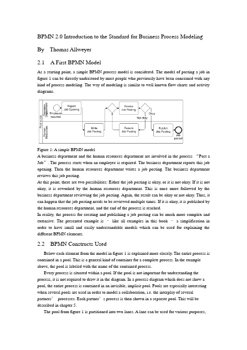
BPMN 2.0 Introduction to the Standard for Business Process Modeling By Thomas Allweyer2.1 A First BPMN ModelAs a starting point, a simple BPMN process model is considered. The model of posting a job in figure 1 can be directly understood by most people who previously have been concerned with any kind of process modeling. The way of modeling is similar to well known flow charts and activity diagrams.Figure 1: A simple BPMN modelA business department and the human resources department are involved in the process “Post a Job”. The process starts when an employee is required. The business department reports this job opening. Then the human resources department writes a job posting. The business department reviews this job posting.At this point, there are two possibilities: Either the job posting is okay, or it is not okay. If it is not okay, it is reworked by the human resources department. This is once more followed by the business department reviewing the job posting. Again, the result can be okay or not okay. Thus, it can happen that the job posting needs to be reviewed multiple times. If it is okay, it is published by the human resources department, and the end of the process is reached.In reality, the process for creating and publishing a job posting can be much more complex and extensive. The presented example is –like all examples in this book –a simplification in order to have small and easily understandable models which can be used for explaining the different BPMN elements.2.2 BPMN Constructs UsedBelow each element from the model in figure 1 is explained more closely. The entire process is contained in a pool. This is a general kind of container for a complete process. In the example above, the pool is labeled with the name of the contained process.Every process is situated within a pool. If the pool is not important for understanding the process, it is not required to draw it in the diagram. In a process diagram which does not show a pool, the entire process is contained in an invisible, implicit pool. Pools are especially interesting when several pools are used in order to model a collaboration, i.e. the interplay of several partners’processes. Each partner’s process is then shown in a separate pool. This will be described in chapter 5.The pool from figure 1 is partitioned into two lanes. A lane can be used for various purposes,e.g. for assigning organizational units, as in the example, or for representing different components within a technical system. In the example, the lanes show witch of the process’s activities are performed by the business department and which by the human resource department.Pools and lanes are also called “swimlanes”. They resemble the partitioning of swimming pools into lanes. Every participant of a competition swims only in his own lane.The process itself begins with the start event “Employee required”. Processes usually have such a start event. Its symbol is a simple circle. In most cases it makes sense to use only one start event, not several ones.A rounded rectangle represents an activity. In an activity something gets done. This is expressed by the activities’names, such as “Report Job Opening”or “Review Job Posting”.The connecting arrows are used for modeling the sequence flow. They represent the sequence in which the different events, activities, and further elements are traversed. Often this is called control flow, but in BPMN there is a second type of flow, the message flow, which influences the control of a process as well, and is therefore some kind of control flow, too. For that reason, the term “sequence flow”is used. For distinguishing it from other kinds of flow, it is important to draw sequence flows with solid lines and filled arrowheads.The process “Post a Job”contains a split: The activity “Review job posting”is followed by a gateway. A blank diamond shape stands for an exclusive gateway. This means that out of several outgoing sequence flows, exactly one must be selected. Every time the right gateway in the job posting-process is reached, a decision must be taken. Either the sequence flow to the right is followed, leading to the activity “Publish Job Posting”, or the one to the left is selected, triggering the activity “Rework Job Posting”. It is not possible to follow both paths simultaneously.The logic of such a decision is also called “exclusive OR”, abbreviated “XOR”. The conditions on the outgoing paths determine which path is selected. If a modeling tool is used and the process has to be executed or simulated by a software program, then it is usually possible to formally define exact conditions. Such formal descriptions, which may be expressed in a programming language, can be stored in special attributes of the sequence flows.If, on the other hand, the purpose of a model is to explain a process to other people,then it is advisable to write informal, but understandable, statements directly into the diagram, next to the sequence flows. The meaning of “okay”and “not okay”after the activity called “Review Job Posting”is clear to humans –a program could not make use of it.Gateways are also used for merging alternative paths. In the sample process, the gateway on the left of the activity “Review Job Posting”merges the two incoming sequence flows. Again, this is an exclusive gateway. It expects that either the activity“Write Job Posting”or “Rework Job Posting”is carried out before the gateway is reached –but not both at the same time. It should be taken care to use a gateway either for splitting or for joining, but not for a combination of both. The last element in the example process is the end event. Like the start event it has a circle as symbol –but with a thick border.2.3 Sequence Flow LogicThe flow logic of the job posting process above is rather easy to understand. In more complex models it is sometimes not clear how the modeled structure exactly is to be interpreted. Therefore it is helpful if the meaning of the sequence flow’s elements is defined in an unambiguous way.The logic of a process diagram’s sequence flow can be explained by “tokens”. Just as in a board game tokens are moved over the board according to the game’s rules, one can imagine moving tokens through a process model according to BPMN’s rules.Every time the process is started, the start event creates a token (cf. figure 2). Since the job posting process is carried out more than once, many tokens can be created in the course of time. Thereby it can happen that the process for one job posting is not yet finished, when the process for posting another job starts. As it moves through the process, each token is independent from the other tokens’movements.Figure 2: A start event creates a tokenThe token that has been created by the start event moves through the sequence flow to the first activity. This activity receives a token, performs its task (in this case it reports a job opening), and then releases it to the outgoing sequence flow (cf. figure 3).Figure 3: An activity receives a token and forwards it after completionThe following activity forwards the token. It then arrives at the merging exclusive gateway. The task of this gateway is simple: It just takes a token that arrives via any incoming sequence flow and moves it to the outgoing sequence flow. This is shown in figure 4. In case A, a token arrives from the left, in case B from below. In both cases the token is routed to the outgoing sequence flow to the right.Figure 4: Routing of a token by a merging exclusive gatewayThe task of the splitting exclusive gateway is more interesting. It takes one arriving token and decides according to the conditions, to which sequence flow it should be moved. In case A in figure 5, the condition “okay”is true, i.e. the preceding review activity has produced a positive result. In this case, the token is moved to the right. Otherwise, if the condition “not okay”is true, the token is moved to the downwards sequence flow (case B).The modeler must define the conditions in such a way that always exactly one of the conditions is true. The BPMN specification does not state how to define conditions and how to check whichconditions are true. Since the considered process is not executed by software, the rather simple statements used here are sufficient. Otherwise, it would be necessary to define the conditions according to the requirements and rules of the software tool.The token may travel several times through the loop for reworking the job posting. Finally it arrives at the end event. This simply removes any arriving token and thus finishes the entire process (figure 6).Figure 5: Routing of a token by a splitting exclusive gatewayThe sequence flow of every process diagram can be simulated in this way with the help of tokens. This allows for analyzing whether the flow logic of a process has been modeled correctly.It should be noted that a token does not represent such a thing as a data object or a document. In the case of the job posting process, it could be imagined to have a document “job posting”flowing through the process. This document could contain all required data, such as the result of the activity “Review Job Posting”. At the splitting gateway, the decision could then be based on this attribute value. However, the BPMN sequence flow is constrained to the pure order of execution. The tokens therefore do not carry any information, other than a unique identifier for distinguishing the tokens from each other. For data objects there are separate BPMN constructs which will be presented in chapter 10.2.4 Presentation OptionsUsually pools are drawn horizontally. The preferred direction of sequence flow is then from left to right. On the other hand, it is also possible to use vertical pools and to draw the sequence flow from top to bottom, as in the example in figure 7.It makes sense to decide for only one of these possibilities –horizontal or vertical. Nevertheless there are modeling tools which only support horizontal modelingFigure 6: An end event removes an arriving tokenFigure 7: Vertical swimlanes and nested lanesFigure 7 also shows an example of nested lanes. The lane labeled “Sales”is partitioned into the two lanes “Sales Force”and “Order Processing”. In principle it is possible to partition these lanes again, etc., although this only makes sense up to a certain level of depth.It is not prescribed where to place the names of pools and lanes. Typical are the variants selected for figure 1 and figure 7. Here the names are placed on the left of the pools or lanes, or at the top for the vertical style, respectively. The name of a pool is separated by a line. The names of the lanes, however, are placed directly within the lanes. A separation line is only used for a lane that is partitioned into further sub-lanes. Lanes can also be arranged as a matrix. The procurement process in figure 8 runs through a business department and the procurement department, both of which span a branch office and the headquarters. When a demand occurs in a branch’s business department, this department reports the demand. In the next step, the procurement is approved by the same department in the headquarters. The central part of the procurement department then closes a contract with a supplier, followed by the branch’s purchasing department carrying out the purchase locally.Although the BPMN specification explicitly describes the possibility of such a matrix presentation, it is hardly ever applied, so far.12.2 Message CorrelationThe contents of the message flows within one conversation are always related to each other. For example, all messages that are exchanged within one instance of the conversation “Process Order for Advertisement”relate to the same advertisement order. It is therefore possible to use the order ID for the correlation, i.e. the assignment of messages to a process instance. If a customer receives an advertisement for approval, he can determine the corresponding order –and thus the process instance –based on the order ID. All messages of a conversation have a common correlation.A simple conversation which is not broken down into other conversations is called communication. Therefore, the lines are called communication links (the specification draft at some places alsocalls them conversation links). A conversation has always communication links to two or more participants.If the end of a communication link is forked, multiple partners of the same type can be part of the communication, otherwise exactly one. “Process Order for Advertisement”has exactly one customer and one advertising agency as participants, but multiple designers. Therefore, the designer’s pool contains a multiple marker. However, having only the multiple marker in the pool is not sufficient. The conversation “Handle order for an illustration”, for example, has only one designer as participant. Therefore, the respective end of the communication link is not forked.12.3 Hierarchies of ConversationsBesides communications, it is also possible to use sub-conversations. Similar to sub-processes they are marked with a ‘+’-sign. The details of a sub-conversation can be described in another conversation diagram. The diagram of a sub-conversation can only contain those participants who are linked to the sub-conversation within the parent diagram.Figure 171 shows the detailed conversation diagram for the sub-conversation “Process Order for Advertisement”As can be seen from this diagram, it is also possible to draw message flows directly into the conversation diagram. Other than collaboration diagrams, conversation diagrams are not allowed to show processes in the pools or choreographies between the pools.Figure 171: Conversation diagram for sub-conversation “Process Order for Advertisement”The diagram contains those message flows that are related to the same order. To be more precise, they relate to the same inquiry. At the beginning, an order has not been placed yet, and not every inquiry turns into an order. Therefore, the common reference point is the inquiry.Besides the explicitly displayed message flows between customer and advertising agency, the diagram also contains the communication “Assignment of Graphics Design”. All message flows of this communication are also related to the same inquiry, but this information is not sufficient for the advertising agency in order to assign all incoming messages correctly. This is due to the fact that availability requests are sent to several designers. The advertising agency has to correctly assign each incoming availability notice to the correct availability request. Thus, additional information is required for correlating these messages, e.g. the IDs of the availability requests.Therefore it is possible to define a separate communication for the message flows between advertising agency and designer. The message exchanges of this communication can also be modeled in a collaboration diagram (figure 172) or in a choreography diagram (figure 173). Of course, it is also possible to show the message flows of the entire sub-conversation within a single diagram (figures 161 and 162 in the previous chapter).Figure 172: Collaboration diagram for communication “Assignment of Graphics Design”Like sub-processes, sub-conversations can also be expanded, i.e. the hexagon is enlarged, and the detailed conversation is shown in its interior. However, it is graphically not easy to include, for example, the contents of figure 171 into an expanded sub-conversation in figure 170. Unfortunately, the BPMN specification draft does not contain any examples for expandedsub-conversations either.。
中英文翻译

附录英文原文:Chinese Journal of ElectronicsVo1.15,No.3,July 2006A Speaker--Independent Continuous SpeechRecognition System Using Biomimetic Pattern RecognitionWANG Shoujue and QIN Hong(Laboratory of Artificial Neural Networks,Institute ol Semiconductors,Chinese Academy Sciences,Beijing 100083,China)Abstract—In speaker-independent speech recognition,the disadvantage of the most diffused technology(HMMs,or Hidden Markov models)is not only the need of many more training samples,but also long train time requirement. This Paper describes the use of Biomimetic pattern recognition(BPR)in recognizing some mandarin continuous speech in a speaker-independent Manner. A speech database was developed for the course of study.The vocabulary of the database consists of 15 Chinese dish’s names, the length of each name is 4 Chinese words.Neural networks(NNs)based on Multi-weight neuron(MWN) model are used to train and recognize the speech sounds.The number of MWN was investigated to achieve the optimal performance of the NNs-based BPR.This system, which is based on BPR and can carry out real time recognition reaches a recognition rate of 98.14%for the first option and 99.81%for the first two options to the Persons from different provinces of China speaking common Chinese speech.Experiments were also carried on to evaluate Continuous density hidden Markov models(CDHMM ),Dynamic time warping(DTW)and BPR for speech recognition.The Experiment results show that BPR outperforms CDHMM and DTW especially in the cases of samples of a finite size.Key words—Biomimetic pattern recognition, Speech recogniton,Hidden Markov models(HMMs),Dynamic time warping(DTW).I.IntroductionThe main goal of Automatic speech recognition(ASR)is to produce a system which will recognize accurately normal human speech from any speaker.The recognition system may be classified as speaker-dependent or speaker-independent.The speaker dependence requires that the system be personally trained with the speech of the person that will be involved with its operation in order to achieve a high recognition rate.For applications on the public facilities,on the other hand,the system must be capable of recognizing the speech uttered by many different people,with different gender,age,accent,etc.,the speaker independence has many more applications,primarily in the general area of public facilities.The most diffused technology in speaker-independent speech recognition is Hidden Markov Models,the disadvantage of it is not only the need of many more training samples,but also long train time requirement.Since Biomimetic pattern recognition(BPR) was first proposed by Wang Shoujue,it has already been applied to object recognition, face identification and face recognition etc.,and achieved much better performance.With some adaptations,such modeling techniques could be easily used within speech recognition too.In this paper,a real-time mandarin speech recognition system based on BPR is proposed,which outperforms HMMs especially in the cases of samples of a finite size.The system is a small vocabulary speaker independent continuous speech recognition one. The whole system is implemented on the PC under windows98/2000/XPenvironment with CASSANN-II neurocomputer.It supports standard 16-bit sound card .II .Introduction of Biomimetic Pattern Recognition and Multi —Weights Neuron Networks1. Biomimetic pattern recognitionTraditional Pattern Recognition aims at getting the optimal classification of different classes of sample in the feature space .However, the BPR intends to find the optimal coverage of the samples of the same type. It is from the Principle of Homology —Continuity ,that is to say ,if there are two samples of the same class, the difference between them must be gradually changed . So a gradual change sequence must be exists between the two samples. In BPR theory .the construction of the sample subspace of each type of samples depends only on the type itself .More detailedly ,the construction of the subspace of a certain type of samples depends on analyzing the relations between the trained types of samples and utilizing the methods of “cov erage of objects with complicated geometrical forms in the multidimensional space”.2.Multi-weights neuron and multi-weights neuron networksA Multi-weights neuron can be described as follows :12m Y=f[(,,,)]W W W X θΦ-…,,Where :12m ,,W W W …, are m-weights vectors ;X is the inputvector ;Φis the neuron’s computation function ;θis the threshold ;f is the activation function .According to dimension theory, in the feature spacen R ,n X R ∈,the function12m (,,,)W W W X Φ…,=θconstruct a (n-1)-dimensional hypersurface in n-dimensional space which isdetermined by the weights12m ,,W W W …,.It divides the n-dimensional space into two parts .If12m (,,,)W W W X θΦ=…, is a closed hypersurface, it constructs a finite subspace .According to the principle of BPR,determination the subspace of a certain type of samples basing on the type of samples itself .If we can find out a set of multi-weights neurons(Multi-weights neuron networks) that covering all the training samples ,the subspace of the neural networks represents the sample subspace. When an unknown sample is in the subspace, it can be determined to be the same type of the training samples .Moreover ,if a new type of samples added, it is not necessary to retrain anyone of the trained types of samples .The training of a certain type of samples has nothing to do with the other ones .III .System DescriptionThe Speech recognition system is divided into two main blocks. The first one is the signal pre-processing and speech feature extraction block .The other one is the Multi-weights neuron networks, which performs the task of BPR .1.Speech feature extractionMel based Campestral Coefficients(MFCC) is used as speech features .It is calculated as follows :A /D conversion ;Endpoint detection using short time energy and Zero crossing rate(ZCR);Preemphasis and hamming windowing ;Fast Fourier transform ;DCT transform .The number of features extracted for each frame is 16,and 32 frames are chosen for every utterance .A 512-dimensiona1-Me1-Cepstral feature vector(1632⨯ numerical values) represented the pronunciation of every word . 2. Multi-weights neuron networks architectureAs a new general purpose theoretical model of pattern Recognition, here BPR is realized by multi-weights neuron Networks. In training of a certain class of samples ,an multi-weights neuron subNetwork should beestablished .The subNetwork consists of one input layer .one multi-weights neuron hidden layer and one output layer. Such a subNetwork can be considered as a mapping 512:F R R →.12m ()min(,,Y )F X Y Y =…,,Where Y i is the output of a Multi-weights neuron. There are m hiddenMulti-weights neurons .i= 1,2, …,m,512X R ∈is the input vector .IV .Training for MWN Networks1. Basics of MWN networks trainingTraining one multi-weights neuron subNetwork requires calculating the multi-weights neuron layer weights .The multi-weights neuron and the training algorithm used was that of Ref.[4].In this algorithm ,if the number of training samples of each class is N,we can use2N -neurons .In this paper ,N=30.12[(,,,)]ii i i Y f s s s x ++=,is a function with multi-vector input ,one scalar quantity output .2. Optimization methodAccording to the comments in IV.1,if there are many training samples, the neuron number will be very large thus reduce the recognition speed .In the case of learning several classes of samples, knowledge of the class membership of training samples is available. We use this information in a supervised training algorithm to reduce the network scales .When training class A ,we looked the left training samples of the other 14 classes as class B . So there are 30 training samples in set1230:{,,}A A a a a =…,and 420 training samples inset 12420:{,,}B B b b =…,b .Firstly select 3 samples from A, and we have a neuron :1123Y =f[(,,,)]k k k a a a x .Let 01_123,=f[(,,,)]A i k k k i A A Y a a a a =,where i= 1,2, (30)1_123Y =f[(,,,)]B j k k k j a a a b ,where j= 1,2,…420;1_min(Y )B j V =,we specify a value r ,0<r<1.If1_*A i Y r V <,removed i a from set A, thus we get a new set (1)A .We continue until the number ofsamples in set ()k Ais(){}k A φ=,then the training is ended, and the subNetwork of class A has a hiddenlayer of1r - neurons.V .Experiment ResultsA speech database consisting of 15 Chinese dish’s names was developed for the course of study. The length of each name is 4 Chinese words, that is to say, each sample of speech is a continuous string of 4 words, such as “yu xiang rou si”,“gong bao ji ding”,etc .It was organized into two sets :training set and test set. The speech signal is sampled at 16kHz and 16-bit resolution .Table 1.Experimental result atof different values450 utterances constitute the training set used to train the multi-weights neuron networks. The 450 ones belong to 10 speakers(5 males and 5 females) who are from different Chinese provinces. Each of the speakers uttered each of the word 3 times. The test set had a total of 539 utterances which involved another 4 speakers who uttered the 15 words arbitrarily .The tests made to evaluate the recognition system were carried out on differentr from 0.5 to 0.95 with astep increment of 0.05.The experiment results at r of different values are shown in Table 1.Obviously ,the networks was able to achieve full recognition of training set at any r .From the experiments ,it was found that0.5r achieved hardly the same recognition rate as the Basic algorithm. In the mean time, theMWNs used in the networks are much less than of the Basic algorithm. Table 2.Experiment results of BPR basic algorithmExperiments were also carried on to evaluate Continuous density hidden Markov models (CDHMM),Dynamic time warping(DTW) and Biomimetic pattern recognition(BPR) for speech recognition, emphasizing the performance of each method across decreasing amounts of training samples as wellas requirement of train time. The CDHMM system was implemented with 5 states per word.Viterbi-algorithm and Baum-Welch re-estimation are used for training and recognition .The reference templates for DTW system are the training samples themselves. Both the CDHMM and DTW technique are implemented using the programs in Ref.[11].We give in Table 2 the experiment results comparison of BPR Basic algorithm ,Dynamic time warping (DTW)and Hidden Markov models (HMMs) method .The HMMs system was based on Continuous density hidden Markov models(CDHMMs),and was implemented with 5 states per name.VI.Conclusions and AcknowledgmentsIn this paper, A mandarin continuous speech recognition system based on BPR is established.Besides,a training samples selection method is also used to reduce the networks scales. As a new general purpose theoretical model of pattern Recognition,BPR could be used in speech recognition too, and the experiment results show that it achieved a higher performance than HMM s and DTW.References[1]WangShou-jue,“Blomimetic (Topological) pattern recognit ion-A new model of pattern recognition theoryand its application”,Acta Electronics Sinica,(inChinese),Vo1.30,No.10,PP.1417-1420,2002.[2]WangShoujue,ChenXu,“Blomimetic (Topological) pattern recognition-A new model of patternrecognition theory and its app lication”, Neural Networks,2003.Proceedings of the International Joint Conference on Neural Networks,Vol.3,PP.2258-2262,July 20-24,2003.[3]WangShoujue,ZhaoXingtao,“Biomimetic pattern recognition theory and its applications”,Chinese Journalof Electronics,V0l.13,No.3,pp.373-377,2004.[4]Xu Jian.LiWeijun et a1,“Architecture research and hardware implementation on simplified neuralcomputing system for face identification”,Neuarf Networks,2003.Proceedings of the Intern atonal Joint Conference on Neural Networks,Vol.2,PP.948-952,July 20-24 2003.[5]Wang Zhihai,Mo Huayi et al,“A method of biomimetic pattern recognition for face recognition”,Neural Networks,2003.Proceedings of the International Joint Conference on Neural Networks,Vol.3,pp.2216-2221,20-24 July 2003.[6]WangShoujue,WangLiyan et a1,“A General Purpose Neuron Processor with Digital-Analog Processing”,Chinese Journal of Electornics,Vol.3,No.4,pp.73-75,1994.[7]Wang Shoujue,LiZhaozhou et a1,“Discussion on the basic mathematical models of neurons in gen eralpurpose neuro-computer”,Acta Electronics Sinica(in Chinese),Vo1.29,No.5,pp.577-580,2001.[8]WangShoujue,Wang Bainan,“Analysis and theory of high-dimension space geometry of artificial neuralnetworks”,Acta Electronics Sinica (in Chinese),Vo1.30,No.1,pp.1-4,2001.[9]WangShoujue,Xujian et a1,“Multi-camera human-face personal identiifcation system based on thebiomimetic pattern recognition”,Acta Electronics Sinica (in Chinese),Vo1.31,No.1,pp.1-3,2003.[10]Ryszard Engelking,Dimension Theory,PWN-Polish Scientiifc Publishers—Warszawa,1978.[11]QiangHe,YingHe,Matlab Porgramming,Tsinghua University Press,2002.中文翻译:电子学报2006年7月15卷第3期基于仿生模式识别的非特定人连续语音识别系统王守觉秦虹(中国,北京100083,中科院半导体研究所人工神经网络实验室)摘要:在非特定人语音识别中,隐马尔科夫模型(HMMs)是使用最多的技术,但是它的不足之处在于:不仅需要更多的训练样本,而且训练的时间也很长。
(完整word版)英语短文中英文翻译

1.Today my friend and I are taking a walk。
suddenly,we are seeing a boy sit on the chair,he is crying,we go and ask him。
“what’s the matter with you” he tell us“I can’t find my dog can you help me”.“yes,I can”.And we help him find his dong .oh it stay underthe big tree!今天我和我的朋友一起去散步。
突然我们看见一个男孩坐在椅子上,他哭的很伤心。
我们走过去问他:“你怎么了”。
他告诉我们:“我的狗不见了,你们能帮我找到它吗”.“是的,我们能帮你找到你的狗”然后我们帮助他找到了他的狗,原来是它呆在一棵大树下。
2。
One day an old man siselling a big elephant.A young man comes to the elephant and begins to look at it slowly。
The old man goes up to him and says inhis ear,“Don't say anything about the elephant before I sell it,then i'll give you some money."“All right,”says the young man.After the old man slles the elephant,he gives the young man some money and says,“Now,can you tell me how you find the bad ears of theelephant?”“I don’t find the bad ears,”says the young man.“Then why do you look at the elephant slowly?”asks the old man。
名篇名译(英译汉)
名篇名译0011.原文:It is an ill wind that blows nobody good.译文:世事皆利弊并存。
赏析:原句结构比较特殊("It is … that …"),理解起来有点困难。
“对谁都没有好处的风才是坏风”,也就是说大多数情况下风对人都是有好处、有坏处,在引申一步就是成了上面的译句。
林佩耵在《中英对译技巧》一书中(第68页)还给了几个相同结构的英文句子。
翻译的前提是理解。
有人指出。
市面上见到的翻译作品,有好多都带有因理解不正确而产生的低级错误,“信”都谈不上还妄谈什么“达”和“雅”!初学翻译的朋友,在理解原文上当不遗余力。
2.原文:Their language was almost unrestrained by any motive of prudence.译文:他们几乎爱讲什么就讲什么,全然不考虑什么谨慎不谨慎。
赏析:如果硬译,译文势必成了“他们的言论几乎不受任何深思熟虑的动机的约束”。
译者本其译,化其滞,将原句一拆为二,充分运用相关翻译技巧,译文忠实、通顺。
3.原文:Get a livelihood,and then practise virtue.译文:先谋生而后修身。
(钱钟书译)赏析:原句是祈使句,译句也传达出了训导的意味。
用“谋生”来译“Get a livelihood",用“修身”来译“practise virtue",可谓精当。
巧的是,原句七个词,译句也是七个汉字。
4.原文:I enjoy the clean voluptuousness of the warm breeze on my skin and the cool support of water.译文:我喜爱那洁净的暖风吹拂在我的皮肤上使我陶然欲醉,也喜爱那清亮的流水把我的身体托浮在水面。
(章振邦译)赏析:"voluptuousness"不会"clean",是"breeze""clean","support"不会"cool", 是"water""cool",这种“甲乙两项相关联,就把原属于形容甲的修饰语移属于乙”的修饰手法叫“移就”(transferred epithet)(《英语修辞赏析》,第145页)。
英文资料翻译原文
英文资料翻译原文Boiler management:General management principles and operating procedures are well known and must be always followed to avoid boiler mishap.With many small package boiler,the automatic control sequence usually ensures that the boiler fire is initially ignited from a diesel oil supply,and changed over to the usual source when ignition is completed.With good management ,to facilitate subsequent starting from cold,the fuel system of large boilers will have been flushed through with diesel oil when the boiler was on light duty immediately prior to being secured.When burning such diesel fuel it is essential for safety that only the correct(small) burner tip should be used.It should be kept in mind that if fire does not light,immediately shut off fuel and vent furance.Complete ignition of fuel in the furance is essential.The burner flame,the smoke indicator and the funnel should be frequently observed.With satisfactory combustion,the flame should appear incandescent with an orange shade at the flame tip,and a faint brownish haze should show at the funnel.If on fist ignition the flame is uncertain,badly shaped and separates from the primary swirler ,momentary opening or closing of air register may correct.The PH value of the boiler feed water should kept between 8 and 9 and the boiler density less than 300 ppm but,if water samples show a heavy concentration of suspended mater,short blow-downs of 20 seconds duration should be given until the sludge content is seen to be reduced.The boiler should be blown down when the oil burner is operating,the water level lowered and then restored to prove the functioning of the low water cut-out and the oil burner start-up equipment.the boiler scum valve should also be operated at this time to keep the water level clear floating scum.Fuel burner components and igniter electrodes should be cleaned weekly and the furance examined to ensure that there are no excess carbon deposits.Tubes in the exhaust gas section of the boiler should be brushed through at about six-monthly intervals,and those in the oil-burning section periodically examined and cleaned as necessary with a wire bristle brush.With correct feed water treatment,blow-down procedures and sludge contents in water samples at a stable level,it should not be necessary to wash out the water side of the boiler more than once every three or four months.Boiler fires may be out of for long periods when a ship is at sea and the boiler steaming maintained by heat input from waste heat recovery plant.This operation is free from hazard,but feed water and boiler water treatment must be maintained to prevent internal deterioration or scale formation.Water level controller must be kept operable to protect external steam-using plant from water “carry-over”danger.If a boiler is isolated from the steam-using system it must be kept either in closed dry storage with a suitable internal desiccant,or completely full of treated water,or under a low steam pressure preferably maintained by a steam-heated coil.Regular testing of boiler protective devices must be implemented.Frequent comparison of drum-mounted and remote reading water levelindicators:discrepancies between these have contributed to failures because of overheating through shortage of water,when a boiler was being oil-fired.If in doubt as to the true boiler water level,i.e.whether a water level indicator sightglass is completely full or empty,when a unit is being oil-fired the fire should be immediately extinguished until the true level is resolved.Procedures should be predetermined and followed in the event of shortage of water,bulging or fracture of plates or furance,or bursting of water tubes .In general,fires should be immediately extinguished by remote tripping of fuel supply valves;forced draught air pressure maintained if there is any risk of escaping steam entering the boiler room;stem pressure relieved if metallic fractures seem possible;and boiler water level maintained,where practicable,until the boiler begins to cool down. Regular operation of soot blowers,if there are fitted,when the boiler is on oil-fired operation.The steam supply line must be thoroughly warmed and drained before blowers are used,the air/fuel ratio increased throughout the action,and the blowers greased after use.Immediate investigation of any high salinity alarms in condensate system,and elimination of any salt water or oil contamination of boiler feed water system. Safety precautions taken before entering a boiler connected to another boiler under steam.Engine governor:A governor maintains the engine speed at the desired value no matter how much load is applied.It achieves this by adjustment of the fuel pump racks.Any change in load will produce a change in engine speed,which will cause the governor to initiate a fuel change.The governor is said to be speed sensing as a speed change has to take place before the governor can react to adjust the fuel setting.The sample mechanical governor employs rotating weights which move outward as the speed increases and inward as the speed reduces.This movement,acting through a system of linkages,can be used to regulate the fuel rack.Rather than having the rotating weights directly move the fuel linkage,hydraulic governor employ a servo system so the rotating weights only need to move a pilot valve in the hydraulic line.This makes the governor more ernors of this type require a speed change to tale place in order that they may initiate fuel rack adjustment.This is known as speed drop and this is a definite speed for each load therefore the governor can not control to a single speed.A modification to the governor hydraulic system introduces a facility known as compensation which allows for further fuel adjustment after the main adjustment has taken place due to speed pensation restores the speed to its original desired value so the engine can operate at the same speed under all loads.Such a governor is said to be isochronous as the engine operates at a single speed.However,the governor is still speed sensing,so it is not ideal for all applications.Speed sensing governor:Where the engine drives an alternator any speed change results in a change in supply frequency.;Large changes in electrical supply frequency can have an adverse effect on sensitive electronic equipment connected to that supply.Where electrical generation is involved it is possible to monitor taking rotational speed as the control signal.Such governors are know as load sensing.It isextremely difficult to make a mechanical governor load sensing,even with a hydraulic system,but an electronic governor can take account of the electrical load applied to the engine and so can be considered “speed sensing”.Electronic governor:Electronic governors essentially comprise two parts,the digital control unit and the hydraulic actuator,which are interlinked but it is useful to consider them separately.Electronic governor controller: The digital control may be considered as a “black box” in which signals are processed to produce a control signal which is sent to the actuator.The controller may be programmed in order to sent points and parameters.The controller is a sensitive piece of electronic equipment and should not be mounted on the engine or in areas where it will be exposed to vibration,humidity or high temperatures.It should be ventilated in order to keep it cool and should be shielded from high-voltage or high-current devices which will cause electromagnetic interference.Similar restriction apply to the location of signal cables.Speed signals are taken from two speed transducers,one on each side of the flexible coupling which attaches the engine to the load.Failure of one transducer produces a minor alarm but allows continued operation with an electronic over speed value may be programmed into the controller in which case detection of over speed will cause the engine to be shut off.If the load is provided by an electrical machine the output from that machine provides a signal for load sharing.Should this transducer fail the load on the engine will be determined by the position of the governor actuator output.The controller can also receive signals from other transducers including in the engine’s air inlet pressure,which allows the fuel to be limited when starting.After processing input signals in accordance with programmed requirements an output signal will be sent to the governor actuator.Electronic governor actuator:The actuator is a hydraulic device which moves the fuel linkage in response to a signal from the digital controller.The operating mechanism is contained with an oil filled casing.Oil pressure is provided by a servomotor pump driven by a shaft connected to the engine camshaft.At the heart of the actuator is the torque motor beam is banlanced where the engine is operating at the desired speed.a.Consider a load increaseThe controller increases current to the torque motor which,in turn,causes the centre adjust end of the torque motor beam to be lowered.Oil flow through the nozzle is reduced ,which increases pressure on the top of the pilot valve plunger.This moves downward,unconering the port which allows pressure oil to the lower face of the power piston,which in turn moves upward, rotating the terminal shaft thereby increasing the fuel to the engine.As the terminal shaft rotates the torque motor beam is pulled upwards by increased tension in the feedback spring,increasing the clearance between the centers adjust and the nozzle.Leakage past the nozzle increases,reducing the pressure on the upper face of the pilot valve plunger and allowing the pilot valve to move upwards.This cuts off further oil to the power piston,and movement of the fuel control linkage ceases.Balance is restored to the torque motor beam with downward force from the feedback spring being matched by upwards force from oilleakage from the nozzle.The engine then operates at an increased fuel setting which matches the new load requirement at the set speed.B.consider a load reductionA decrease in load produces a reduction in current acting on the torque motor,which tends to turn the beam in an anti-clockwise direction about the torque motor pivot,resulting in an increased clearance between the centre adjust and the nozzle.Pressure reduces on the upper face of the pilot valve plunger and the pilot valve moves upwards,allowing the lower face of the power piston to connect with the geromotor pump suction.the power piston moves downwards ,rotating the terminal shaft which reduces fuel to the engine and tension in the feedback spring.The center adjust end of the torque motor beam is forced down,thereby reducing clearance between the centre adjust and the nozzle.Leakage past the nozzle reduces pressure on the upper face of the pilot valve increases and the pilot valve moves upwards,shuting off the connection between the lower face of the power piston and pump suction .The engine now operates with reduced load and reduced fuel,but at the same original speed.。
- 1、下载文档前请自行甄别文档内容的完整性,平台不提供额外的编辑、内容补充、找答案等附加服务。
- 2、"仅部分预览"的文档,不可在线预览部分如存在完整性等问题,可反馈申请退款(可完整预览的文档不适用该条件!)。
- 3、如文档侵犯您的权益,请联系客服反馈,我们会尽快为您处理(人工客服工作时间:9:00-18:30)。
GRA VITY RETAINING−WALL1. INTRODUCTIONRetaining walls are structures used to provide stability for earth or other material where conditions disallow the mass to assume its natural slope, and are commonly used to hold back or support soilbanks,coal or ore piles, and water.Retaining walls are classified, based on the method of achieving stability, into six principal types (Fig.1). The gravity-wall depends upon its weight, as the name implies, for stability. The cantilever wall is a reinforced-concrete wall that utilizes cantilever action to retain the mass behind the wall from assuming a natural slope. Stability of this wall is partially achieved from the weight of soil on the heel portion of the base slab. A counterfort retaining wall is similar to a cantilever retaining wall, except that it is used where the cantilever is long or for very high pressures behind wall and has counterforts, which tie the wall and base together, built at intervals along the wall to reduce the bending moments and sheers. As indicated in Fig.1c, the counterfort is behind the wall and subjected to tensile forces. A buttressed retaining wall is similar to a counterfort wall, except that the bracing is in front of the wall and is in compression instead of tension. Two other types of walls not considered further are crib walls, which are built-up members of pieces of precast concrete, metal, or timber and are supported by anchor pieces embedded in the soil for stability, and semigravity walls, which are walls intermediate between a true gravity and a cantilever wall.(a)(b)(e)(f)Approah slabFigure.1 Types of retaining walls: (a) Gravity walls of stone masonry, brick, or plainconcrete. Weight provides overturning and sliding stability; (b)cantilever wall; (c) counterfort, or buttressed wall. If backfill covers counterforts, the wall is termed a counterfort; (d) crib wall; (e) semigravity wall (small amount of steel reinforcement is used); (f) bridge abutment.Bridge abutments (Fig.1f) are often retaining walls with wing wall extensions to retain the approach fill and provide protection against erosion. They differ in two major respects from the usual retaining wall in:1. They carry end reaction from the bridge span.2. They are restrained at the top so that an active earth pressure is unlikely to develop. Foundation walls of buildings including residential construction are retaining walls whose function is to contain the earth out of basements.Retaining walls must be of adequate proportions to resist overturning for (or excessive tilting) and sliding as well as being structurally adequate.Terms used in retaining-wall design are shown in Fig.2. Note that the “toe ” is both the front base projection and the forward edge ; similarly for the “heel ”.Figure.2 Principal terms used with retaining walls.2. COMMON PROPORTIONS OF GRA VITY WALLRetaining-wall design proceeds with the selection of tentative dimensions, which are then analyzed for stability and structural requirements and are revised as required. Since this a trial process, several solutions to the problem may be obtained, all of which are satisfactory. A computer solution greatly simplifies the work in retaining-wall design and provides the only practical means to optimize the design.Slape changeto reduceconcrete (a)(b)Figure.3 (a)Tentative demensions for a gravity retaining wall; (b)broken back retaining wall.Gravity-wall dimensions may be may be taken as shown in Fig.3. Gravity walls, generally, are trapezoidal-shaped but also may be built with broken backs. The base other dimensions should be such that the resultant falls within the middle one-third of the base. The top width of the stem should be on the order of 0.30m.If the heel projection is only 100 to 150mm, the Coulomb equation may be used for evaluating the lateral earth pressure, with the surface of sliding taken along the back face of the wall. The Rankine solution may also be used on a section taken through the heel. Because of the massive proportion and resulting low concrete stresses, low-strength concrete can generally used for the wall construction.A critical section for analysis of tensile flexure stresses will occur through the junction of the toe portion at the front face of wall.°-α+δ)°-α+δ)ββsin a cos a (b)(a)Figure.4 Forces on a gravity wall.(a)Coulmomb analysis;(b)Rankine analysis.3. GRA VITY W ALL FORCEThe forces on a gravity wall are as indicated in Fig.4.The active earth pressure is computed by either the Rankine or Coulomb methods. If the Coulomb method is used, it is assumed that there is incipient sliding on the back face of the wall, and the pressure acts at the angle of wall friction δ to a normal with the wall. The Rankine solution applies to Pa acting at the angle β on a vertical plane through the heel. The vector can then be added to the weight vector of the wedge of soil W between the vertical plane and back of the wall to get the direction and magnitude of the resultant Pa on the wall. The vertical resultant R acting on the base is equal to the sum of the forces acting downward, and will have an eccentricity e with respect to the geometrical center of the base. Taking moments about the toe,=x sum of overturning moments(net)/RIf the width of the base is B, the eccentricity of the base can then be computed asx Be -=2ββ=P sin a v a =P h cos W s =weight of abcdW c =weight of concrete of entire wall systemF=F r /P h ≥1.5F R ′+c ′+P p B P p=12γH p ′p K Figure.5 Forces involvedin the sliding stability of a retaining wall.4. STABILITY OF GRA VITY W ALLRetaining walls must provide adequate stability against sliding, as shown in Fig.5. The soil in front of the wall provides a passive-earth-pressure resistance, as the wall tends to slide into it. If the soil is excavated or eroded after the wall is built, the passive-pressure component is not available and sliding instability may occur. If there is certainty of no loss of the toe soil, the designer may use the passive pressure in this zone as part of the sliding resistance.Additional sliding stability may be derived from the use of a key beneath the base. Unless the key is quite deep, however, the sliding zone (Fig.6) may bridge over the key in taking that path of least resistance. A key into firm soil or rock may be quite advantageous, since the resistance is now the force necessary to sheer the key from the base slab.γ1p=P 2pK H p(b)(a)(c)this inclined planeFigure.6 Stability against sliding using a base key.(a)Base key near stem so that stem steel maybe run into the key;but(b)the sliding surface may develop as shown here where little aid is gained from using the key;(c)heel key which presents two possible modes of failure(passive and slip along the plane).The best key location is at the heel as indicated in Fig.6. This location creates aslightly lager sliding-resistance distance L, as well as an additional component of forcefrom the upward-sloping plane. The lesser of the two values1. Passive pressure developed to the bottom of the key.2. Sliding resistance up plane ab . is used in computing sliding stability.The sliding resistance along the base is taken as fR , where R includes all the vertical forces, including the vertical component of Pa, acting on the base.The coefficient of friction between the base and the soil may be taken as f =tg φ to 0.67 tgand base cohesion cas c=0.5c to 0.75cThe base soil is usually compacted prior to pouring the base slab; however, the wet concrete will always attach to the ground such that f =tg φ is obtained. The cohesion may be considerably destroyed from water and remolding; thus values of 0.5 to 0.75c are more appropriate.The safety factor against sliding should be at least 1.5 for cohesionless backfill and about 2.0 for cohesive backfill computed as follows:sliding F =sum resisting forces /sum deriving forcesThe usual safety factor against overturning with respect to the toe is 1.5, with a value of 2.0 suggested for cohesive soil:g overturnin F =sum of moments to resist overturning /sum of overturning moments (d)The safety factor can be computed in several ways depending on the interpretation of what goes in the numerator or denominator of Eqs. (a) and (b).-α+δ)-α+δ)°°Figure.7 Design of a gravity retaining wall with criticalpoints indicated.f=V/t5. DESIGN OF GRA VITY W ALLThe design of gravity wall will be illustrated by an example.The first step in the design of a gravity wall is to select proportions. Figure 3 is used as a guide for selecting initial wall dimensions. Figure.7 indicates critical sections and the method of computing concrete stresses. Also shown are the allowable ACI (USD) Code concrete stresses in Fps and SI units.(a)(b)Figure.8Example Design a solidg.8a. gravity wall to retain a 5.5m embankment. The general wall geometry is shown on FiSoil data:Mpa f c21,c t f f 42.0 ,65.0=φ c c f v 16.0 ,85.0=φ SOLUTIONStep1 Find the later wall force using the Rankine Ka:Ka==-)245(02ϕtg =-)23245(02tg 0.321 Pa=KN Ka H 142321.01.75.17212122=⨯⨯⨯=γKN P h 13910cos 1420==,KN P V 2510sin 1420==Step2 Computer wall stability. Neglect soil toe and not use passive pressure.*Using appropriciation of centroid 2.27/3 from shear plane. (a) The overturning safety factor is >1.5 O.K.(b) The sliding factor of safety (and neglecting any passive pressure) is Take cohesion c=Take cohesion >1.5 also O.K.Step3 Locate resultant on base and eccentricity:m x B e 50.020.17.12 <6L O.K.Step4 Computer actual soil pressure:(max)253]4.35.061[14.3457)61(kpa L e A P q<275kpa O.K. =16(min)Step5 Check shear and tensile bending stresses in toe at 0.15m from edge; refer to Fig.8b.(a) Shear check: q=253-69.7xV=27.69253)7.69253(2x x dx x xat x=0.15m and V=37 KN.For load factor=2, d=D for no rebars, andkpa bd V LF v a 2.829.01372=⨯⨯=⨯=kpa v c 6231021)85.0(16.03=⨯=>82kap O.K. (b) Tension check:67.692253320x x Vdx M xat x=0.15m and M=2.81m KNFor LF=2 and 62bh S x =Actual kpa bh M LF f t 429.0181.226)(622=⨯⨯⨯==O.K. Step6 Approximate check t f at 1/2 wall height (3.5m from top; ≃3.75 at slope):Approx. M= cos 212y Ka HM=m KN 6.4810cos 375.3321.075.35.172102Find wall h at 3.5m by proportion:8.56.25.3h m h 57.1 and h=1.57+0.5=2.07m Actual (approx.)kpa bh M LF f t 13607.216.4826)(622=⨯⨯⨯==≪1250kpa O.K. Note this check is very conservative as it neglects both wall batter and the weight of stem above 3.5m level to reduce t f . Wall proportions are adequate. Might consider (1) using boulder filler (2) using c f =14 or 17 Mpa concrete.。