翻译的英文原文
高级英语lesson2原文及其翻译

“Hiroshima! Everybody off!” That must be what the man in the Japanese stationmaster's uniform shouted, as the fastest train in the world slipped to a stop in Hiroshima Station. I did not understand what he was saying. First of all, because he was shouting in Japanese. And secondly, because I had a lump in my throat and a lot of sad thoughts on my mind that had little to do with anything a Nippon railways official might say. The very act of stepping on this soil, in breathing this air of Hiroshima, was for me a far greater adventure than any trip or any reportorial assignment I'd previously taken. Was I not at the scene of the crime?The Japanese crowd did not appear to have the same preoccupations that I had. From the sidewalk outside the station, things seemed much the same as in other Japanese cities. Little girls and elderly ladies in kimonos rubbed shoulders with teenagers and women in western dress. Serious looking men spoke to one another as if they were oblivious of the crowds about them, and bobbed up and down re-heatedly in little bows, as they exchanged the ritual formula of gratitude and respect: "Tomo aligato gozayimas." Others were using little red telephones that hung on the facades of grocery stores and tobacco shops."Hi! Hi!" said the cab driver, whose door popped open at the very sight of a traveler. "Hi", or something that sounds very much like it, means "yes". "Can you take me to City Hall?" He grinned at me in the rear-view mirror and repeated "Hi!" "Hi! ’ We set off at top speed throug h the narrow streets of Hiroshima. The tall buildings of the martyred city flashed by as we lurched from side to side in response to the driver's sharp twists of the wheel.Just as I was beginning to find the ride long, the taxi screeched to a halt, and the driver got out and went over to a policeman to ask the way. As in Tokyo, taxi drivers in Hiroshima often know little of their city, but to avoid loss of face before foreigners, will not admit their ignorance, and will accept any destination without concern for how long it may take them to find it.At last this intermezzo came to an end, and I found myself in front of the gigantic City Hall. The usher bowed deeply and heaved a long, almost musical sigh, when I showed him the invitation which the mayor had sent me in response to my request for an interview. "That is not here, sir," he said in English. "The mayor expects you tonight for dinner with other foreigners or, the restaurant boat. See? This is where it is.” He sketched a little map for me on the back of my invitation.Thanks to his map, I was able to find a taxi driver who could take me straight to the canalembankment , where a sort of barge with a roof like one on a Japanese house was moored . The Japanese build their traditional houses on boats when land becomes too expensive. The rather arresting spectacle of little old Japan adrift adrift amid beige concrete skyscrapers is the very symbol of the incessant struggle between the kimono and the miniskirt.At the door to the restaurant, a stunning, porcelain-faced woman in traditional costume asked me to remove my shoes. This done, I entered one of the low-ceilinged rooms of the little floating house, treading cautiously on the soft matting and experiencing a twinge of embarrassment at the prospect of meeting the mayor of Hiroshima in my socks.He was a tall, thin man, sad-eyed and serious. Quite unexpectedly, the strange emotion which had overwhelmed me at the station returned, and I was again crushed by the thought that I now stood on the site of the first atomic bombardment, where thousands upon thousands of people had been slain in one second, where thousands upon thousands of others had lingered on to die in slow agony .The introductions were made. Most of the guests were Japanese, and it was difficult for me to ask them just why we were gathered here. The few Americans and Germans seemed just as inhibited as I was. "Gentlemen," said the mayor, "I am happy to welcome you to Hiroshima."Everyone bowed, including the Westerners. After three days in Japan, the spinal column becomes extraordinarily flexible."Gentlemen, it is a very great honor to have you her e in Hiroshima."There were fresh bows, and the faces grew more and more serious each time the name Hiroshima was repeated."Hiroshi ma, as you know, is a city familiar to everyone,” continued the mayor."Yes, yes, of course,” murmured the company, more and more agitated."Seldom has a city gained such world renown, and I am proud and happy to welcome you to Hiroshima, a town known throughout the world for its--- oysters".I was just about to make my little bow of assent, when the meaning of these last words sank in, jolting me out of my sad reverie ."Hiroshima –oysters? What about the bomb and the misery and humanity's most heinous crime?" While the mayor went on with his speech in praise of southern Japanese sea food, I cautiously backed away and headed toward the far side of the room, where a few men were talkingamong themselves and paying little attention to the mayor's speech. "You look puzzled," said a small Japanese man with very large eye-glasses."Well, I must confess that I did not expect a speech about oysters here. I thought that Hiroshima still felt the impact of the atomic impact .""No one talks about it any more, and no one wants to, especially, the people who were born here or who lived through it. "Do you feel the same way, too?""I was here, but I was not in the center of town. I tell you this because I am almost an old man. There are two different schools of thought in this city of oysters, one that would like to preserve traces of the bomb, and the other that would like to get rid of everything, even the monument that was erected at the point of impact. They would also like to demolish the atomic museum.""Why would they want to do that?""Because it hurts everybody, and because time marches on. That is why." The small Japanese man smiled, his eyes nearly closed behind their thick lenses. "If you write about this city, do not forget to say that it is the gayest city in Japan, even it many of the town's people still bear hidden wounds, and burns."Like any other, the hospital smelled of formaldehyde and ethere . Stretchers and wheelchairs lined the walls of endless corridors, and nurses walked by carrying Stretchers instruments, the very sight of which would send shivers down the spine of any healthy visitor. The so-called atomic section was located on the third floor. It consisted of 17 beds."I am a fisherman by trade. I have been here a very long time, more than twenty years, "said an old man in Japanese pajamas. “What is wrong with you?”"Something inside. I was in Hiroshima when it happened. I saw the fire ball. But I had no burns on my face or body. I ran all over the city looking for missing friends and relatives. I thought somehow I had been spared. But later my hair began to fall out, and my belly turned to water. I felt sick, and ever since then they have been testing and treating me. " The doctor at my side explained and commented upon the old man's story, "We still hare a handful of patients here who are being kept alive by constant car e. The other s died as a result of their injuries, or else committed suicide . ""Why did they commit suicide?""It is humiliating to survive in this city. If you bear any visible scars of atomic burns, your children will encounter prejudice on the par t of those who do not. No one will marry the daughter or the niece of an atomic bomb victim. People are afraid of genetic damage from the radiation." The old fisherman gazed at me politely and with interest.Hanging over the patient was a big ball made of bits of brightly colored paper, folded into the shape of tiny birds. "What's that?" I asked."Those are my lucky birds. Each day that I escape death, each day of suffering that helps to free me from earthly cares, I make a new little paper bird, and add it to the others. This way I look at them and congratulate myself of the good fortune that my illness has brought me. Because, thanks to it, I have the opportunity to improve my character."Once again, outside in the open air, I tore into little pieces a small notebook with questions that I'd prepared in advance for inter views with the patients of the atomic ward. Among them was the question: Do you really think that Hiroshima is the liveliest city in Japan? I never asked it. But I could read the answer in every eye.“广岛到了!大家请下车!”当世界上最快的高速列车减速驶进广岛车站并渐渐停稳时,那位身着日本火车站站长制服的男人口中喊出的一定是这样的话。
英文原文及翻译

Vera Wang Honors Her Chinese Roots王薇薇以中国根为傲With nuptials(婚礼) season in full swing, Vera Wang’s wedding dress remains at the top of many a bride’s(婚礼) wish list. The designer, who recently took home the lifetime achievement award from the Council of Fashion Designers of America, has been innovating in bridal design for years—using color, knits and even throwing fabric into a washing machine.随着婚礼季的全面展开,王薇薇(Vera Wang)婚纱依然是许多新娘愿望清单上的首选。
王薇薇最近刚拿到美国时装设计师协会(Council of Fashion Designers of America)颁发的终生成就奖。
多年来她一直在婚纱设计领域进行创新──运用色彩和编织手法,甚至将面料扔进洗衣机里。
Ms. Wang said that her latest collection is about construction. “I had felt that I had really messed that vocabulary of perfection for brides for a while, where there’s six fabrics to a skirt, ” she said. “I wanted to go back to something that maybe was what I started with, but in a whole new way, and that would be architecture—not simplicity—but maybe minimalism.”王薇薇说,她的最新婚纱系列重点在于构建。
名篇名译(英译汉)

名篇名译0011.原文:It is an ill wind that blows nobodygood.译文:世事皆利弊并存。
赏析:原句结构比较特殊("Itis…that…"),理解起来有点困难。
“对谁都没有好处的风才是坏风”,也就是说大多数情况下风对人都是有好处、有坏处,在引申一步就是成了上面的译句。
林佩耵在《中英对译技巧》一书中(第68页)还给了几个相同结构的英文句子。
翻译的前提是理解。
有人指出。
市面上见到的翻译作品,有好多都带有因理解不正确而产生的低级错误,“信”都谈不上还妄谈什么“达”和“雅”!初学翻译的朋友,在理解原文上当不遗余力。
2.原文:Their languag e was almostunrestr ainedby any motiveof prudenc e.译文:他们几乎爱讲什么就讲什么,全然不考虑什么谨慎不谨慎。
赏析:如果硬译,译文势必成了“他们的言论几乎不受任何深思熟虑的动机的约束”。
译者本其译,化其滞,将原句一拆为二,充分运用相关翻译技巧,译文忠实、通顺。
3.原文:Get a livelih ood,and then practis e virtue.译文:先谋生而后修身。
(钱钟书译)赏析:原句是祈使句,译句也传达出了训导的意味。
用“谋生”来译“Getalivelih ood",用“修身”来译“practis e virtue",可谓精当。
巧的是,原句七个词,译句也是七个汉字。
4.原文:I enjoy the clean voluptu ousnes s of the warm breezeon my skin and the cool support of water.译文:我喜爱那洁净的暖风吹拂在我的皮肤上使我陶然欲醉,也喜爱那清亮的流水把我的身体托浮在水面。
英文翻译原文

南京师范大学泰州学院英文翻译原文年级: 2011级学号:12110330 姓名:申佳佳系部:信息工程学院专业:通信工程题目:基于C51的数字测速仪设计与仿真指导教师:焦蓬蓬2015 年 4 月 5 日Linux - Operating system of cybertimesThough for a lot of people , regard Linux as the main operating system to make u p huge work station group, finish special effects of " Titanic " make , already can be re garded as and show talent fully. But for Linux, this only numerous news one of. Rece ntly, the manufacturers concerned have announced that support the news of Linux to i ncrease day by day, users' enthusiasm to Linux runs high unprecedentedly too. Then, Linux only have operating system not free more than on earth on 7 year this piece wh at glamour, get the favors of such numerous important software and hardware manufa cturers as the masses of users and Orac le , Informix , HP , Sybase , Corel , Intel , Net scape , Dell ,etc. , OK?1.The background of Linux and characteristicLinux is a kind of " free (Free ) software ": What is called free, mean users can o btain the procedure and source code freely , and can use them freely , including revise or copy etc.. It is a result of cybertimes, numerous technical staff finish its research a nd development together through Inte rnet, countless user is it test and except fault , c an add user expansion function that oneself make conveniently to participate in. As the most outstanding one in free software, Linux has characteristic of the following:(1)Totally follow POSLX standard, expand the network operating system of sup porting all AT&T and BSD Unix characteristic. Because of inheritting Unix outstandi ng design philosophy , and there are clean , stalwart , high-efficient and steady kernels , their all key codes are finished by Li nus Torvalds and other outstanding programmer s, without any Unix code of AT&T or Berkeley, so Linu x is not Unix, but Linux and Unix are totally compatible. (2)Real many tasks, multi-user's system, the built-in n etwork supports, can be with such seamless links as NetWare , Windows NT , OS/2 , Unix ,etc.. Network in various kinds of Unix it tests to be fastest in comparing and ass ess efficiency. Support such many kinds of files systems as FAT16 , FAT32 , NTFS , E x t2FS , ISO9600 ,etc. at the same time .(3) Can operate it in many kinds of hardwares platform , including such processo rs as Alpha , SunSparc , PowerPC , MIPS ,etc., to various kinds of new-type periphera l hardwares, can from distribute on global numerous programmer there getting suppor t rapidly too.(4) To that the hardware requires lower, can obtain very good performance on mo re low-grade machine , what deserves particular mention is Linux outstanding stability , permitted " year " count often its running times.2.Main application of Linux At present,Now, the application of Linux mainly includes:(1) Internet/Intranet: This is one that Linux was used most at present, it can offer andinclude Web server , all such Inter net services as Ftp server , Gopher server , SM TP/POP3 mail server , Proxy/Cache server , DNS server ,etc.. Linux kernel supports I Palias , PPP and IPtunneling, these functions can be used for setting up fictitious host computer , fictitious service , VPN (fictitious special-purpose network ) ,etc.. Operatin g Apache Web server on Linux mainly, the occupation rate of market in 1998 is 49%, far exceeds the sum of such several big companies as Microsoft , Netscape ,etc..(2) Because Linux has outstanding networking ability , it can be usedin calculati ngdistributedly large-scaly, for instance cartoon making , scientific caculation , database and file server ,etc..(3) As realization that is can under low platform fullness of Unix that operate , ap ply at all levels teaching and research work of universities and colleges extensively, if Mexico government announce middle and primary schools in the whole country dispo se Linux and offer Internet service for student already.(4) Tabletop and handling official business appliedly. Application number of peo ple of in this respect at present not so good as Windows of Microsoft far also, reason i ts lie in Lin ux quantity , desk-top of application software not so good as Windows ap plication far not merely, because the characteristic of the freedom software makes it n ot almost have advertisement that support (though the function of Star Office is not second to MS Office at the same time, but there are actually few people knowing).3.Can Linux become a kind of major operating system?In the face of the pressure of coming from users that is strengthened day by day, more and more commercial companies transplant its application to Linux platform, co mparatively important i ncident was as follows, in 1998.(1)Compaq and HP determine to put forward user of requirement truss up Linux at their servers , IBM and Dell promise to offer customized Linux system to user too.(2)Lotus announce, Notes the next edition include one special-purpose edition in Linux.(3)Corel Company transplants its famous WordPerfect to on Linux, and free issue. Corel also plans to move the other figure pattern process products to Linux platfor m completely.(4)Main database producer: Sybase , Informix , Oracle , CA , IBM have already been transplanted one's own database products to on Linux, or has finished Beta editio n, among them Oracle and Informix also offer technical support to their products.4.The gratifying one is, some farsighted domestic corporations have begun to try hard to change this kind of current situation already. Stone Co. not long ago is it inves t a huge sum of money to claim , regard Linux as platform develop a Internet/Intranet solution, regard this as the core and launch Stone's system integration business , plan t o set up nationwide Linux technical support organization at the same time , take the le ad to promote the freedom software application and development in China. In additio n domestic computer Company , person who win of China , devoted to Linux relevant software and hardware application of system popularize too. Is it to intensification th at Linux know , will have more and more enterprises accede to the ranks that Linux w ill be used with domestic every enterprise to believe, more software will be planted in Linux platform. Meanwhile, the domestic university should regard Linux as the origin al version and upgrade already existing Unix content of courses , start with analysing t he source code and revising the kernel and train a large number of senior Linux talent s, improve our country's own operating system. Having only really grasped the operati ng system, the software industry of our country could be got rid of and aped sedulously at present, the passive state led by the nose by others, create conditions for revitalizi ng the software industry of our country fundamentally.。
中英文翻译英文原文
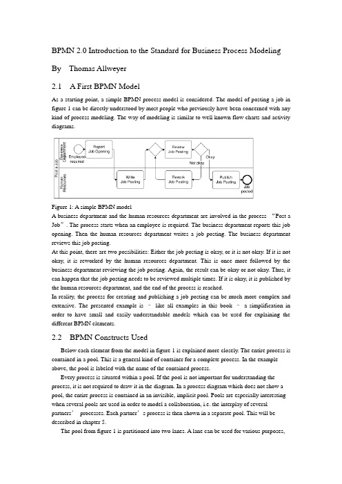
BPMN 2.0 Introduction to the Standard for Business Process Modeling By Thomas Allweyer2.1 A First BPMN ModelAs a starting point, a simple BPMN process model is considered. The model of posting a job in figure 1 can be directly understood by most people who previously have been concerned with any kind of process modeling. The way of modeling is similar to well known flow charts and activity diagrams.Figure 1: A simple BPMN modelA business department and the human resources department are involved in the process “Post a Job”. The process starts when an employee is required. The business department reports this job opening. Then the human resources department writes a job posting. The business department reviews this job posting.At this point, there are two possibilities: Either the job posting is okay, or it is not okay. If it is not okay, it is reworked by the human resources department. This is once more followed by the business department reviewing the job posting. Again, the result can be okay or not okay. Thus, it can happen that the job posting needs to be reviewed multiple times. If it is okay, it is published by the human resources department, and the end of the process is reached.In reality, the process for creating and publishing a job posting can be much more complex and extensive. The presented example is –like all examples in this book –a simplification in order to have small and easily understandable models which can be used for explaining the different BPMN elements.2.2 BPMN Constructs UsedBelow each element from the model in figure 1 is explained more closely. The entire process is contained in a pool. This is a general kind of container for a complete process. In the example above, the pool is labeled with the name of the contained process.Every process is situated within a pool. If the pool is not important for understanding the process, it is not required to draw it in the diagram. In a process diagram which does not show a pool, the entire process is contained in an invisible, implicit pool. Pools are especially interesting when several pools are used in order to model a collaboration, i.e. the interplay of several partners’processes. Each partner’s process is then shown in a separate pool. This will be described in chapter 5.The pool from figure 1 is partitioned into two lanes. A lane can be used for various purposes,e.g. for assigning organizational units, as in the example, or for representing different components within a technical system. In the example, the lanes show witch of the process’s activities are performed by the business department and which by the human resource department.Pools and lanes are also called “swimlanes”. They resemble the partitioning of swimming pools into lanes. Every participant of a competition swims only in his own lane.The process itself begins with the start event “Employee required”. Processes usually have such a start event. Its symbol is a simple circle. In most cases it makes sense to use only one start event, not several ones.A rounded rectangle represents an activity. In an activity something gets done. This is expressed by the activities’names, such as “Report Job Opening”or “Review Job Posting”.The connecting arrows are used for modeling the sequence flow. They represent the sequence in which the different events, activities, and further elements are traversed. Often this is called control flow, but in BPMN there is a second type of flow, the message flow, which influences the control of a process as well, and is therefore some kind of control flow, too. For that reason, the term “sequence flow”is used. For distinguishing it from other kinds of flow, it is important to draw sequence flows with solid lines and filled arrowheads.The process “Post a Job”contains a split: The activity “Review job posting”is followed by a gateway. A blank diamond shape stands for an exclusive gateway. This means that out of several outgoing sequence flows, exactly one must be selected. Every time the right gateway in the job posting-process is reached, a decision must be taken. Either the sequence flow to the right is followed, leading to the activity “Publish Job Posting”, or the one to the left is selected, triggering the activity “Rework Job Posting”. It is not possible to follow both paths simultaneously.The logic of such a decision is also called “exclusive OR”, abbreviated “XOR”. The conditions on the outgoing paths determine which path is selected. If a modeling tool is used and the process has to be executed or simulated by a software program, then it is usually possible to formally define exact conditions. Such formal descriptions, which may be expressed in a programming language, can be stored in special attributes of the sequence flows.If, on the other hand, the purpose of a model is to explain a process to other people,then it is advisable to write informal, but understandable, statements directly into the diagram, next to the sequence flows. The meaning of “okay”and “not okay”after the activity called “Review Job Posting”is clear to humans –a program could not make use of it.Gateways are also used for merging alternative paths. In the sample process, the gateway on the left of the activity “Review Job Posting”merges the two incoming sequence flows. Again, this is an exclusive gateway. It expects that either the activity“Write Job Posting”or “Rework Job Posting”is carried out before the gateway is reached –but not both at the same time. It should be taken care to use a gateway either for splitting or for joining, but not for a combination of both. The last element in the example process is the end event. Like the start event it has a circle as symbol –but with a thick border.2.3 Sequence Flow LogicThe flow logic of the job posting process above is rather easy to understand. In more complex models it is sometimes not clear how the modeled structure exactly is to be interpreted. Therefore it is helpful if the meaning of the sequence flow’s elements is defined in an unambiguous way.The logic of a process diagram’s sequence flow can be explained by “tokens”. Just as in a board game tokens are moved over the board according to the game’s rules, one can imagine moving tokens through a process model according to BPMN’s rules.Every time the process is started, the start event creates a token (cf. figure 2). Since the job posting process is carried out more than once, many tokens can be created in the course of time. Thereby it can happen that the process for one job posting is not yet finished, when the process for posting another job starts. As it moves through the process, each token is independent from the other tokens’movements.Figure 2: A start event creates a tokenThe token that has been created by the start event moves through the sequence flow to the first activity. This activity receives a token, performs its task (in this case it reports a job opening), and then releases it to the outgoing sequence flow (cf. figure 3).Figure 3: An activity receives a token and forwards it after completionThe following activity forwards the token. It then arrives at the merging exclusive gateway. The task of this gateway is simple: It just takes a token that arrives via any incoming sequence flow and moves it to the outgoing sequence flow. This is shown in figure 4. In case A, a token arrives from the left, in case B from below. In both cases the token is routed to the outgoing sequence flow to the right.Figure 4: Routing of a token by a merging exclusive gatewayThe task of the splitting exclusive gateway is more interesting. It takes one arriving token and decides according to the conditions, to which sequence flow it should be moved. In case A in figure 5, the condition “okay”is true, i.e. the preceding review activity has produced a positive result. In this case, the token is moved to the right. Otherwise, if the condition “not okay”is true, the token is moved to the downwards sequence flow (case B).The modeler must define the conditions in such a way that always exactly one of the conditions is true. The BPMN specification does not state how to define conditions and how to check whichconditions are true. Since the considered process is not executed by software, the rather simple statements used here are sufficient. Otherwise, it would be necessary to define the conditions according to the requirements and rules of the software tool.The token may travel several times through the loop for reworking the job posting. Finally it arrives at the end event. This simply removes any arriving token and thus finishes the entire process (figure 6).Figure 5: Routing of a token by a splitting exclusive gatewayThe sequence flow of every process diagram can be simulated in this way with the help of tokens. This allows for analyzing whether the flow logic of a process has been modeled correctly.It should be noted that a token does not represent such a thing as a data object or a document. In the case of the job posting process, it could be imagined to have a document “job posting”flowing through the process. This document could contain all required data, such as the result of the activity “Review Job Posting”. At the splitting gateway, the decision could then be based on this attribute value. However, the BPMN sequence flow is constrained to the pure order of execution. The tokens therefore do not carry any information, other than a unique identifier for distinguishing the tokens from each other. For data objects there are separate BPMN constructs which will be presented in chapter 10.2.4 Presentation OptionsUsually pools are drawn horizontally. The preferred direction of sequence flow is then from left to right. On the other hand, it is also possible to use vertical pools and to draw the sequence flow from top to bottom, as in the example in figure 7.It makes sense to decide for only one of these possibilities –horizontal or vertical. Nevertheless there are modeling tools which only support horizontal modelingFigure 6: An end event removes an arriving tokenFigure 7: Vertical swimlanes and nested lanesFigure 7 also shows an example of nested lanes. The lane labeled “Sales”is partitioned into the two lanes “Sales Force”and “Order Processing”. In principle it is possible to partition these lanes again, etc., although this only makes sense up to a certain level of depth.It is not prescribed where to place the names of pools and lanes. Typical are the variants selected for figure 1 and figure 7. Here the names are placed on the left of the pools or lanes, or at the top for the vertical style, respectively. The name of a pool is separated by a line. The names of the lanes, however, are placed directly within the lanes. A separation line is only used for a lane that is partitioned into further sub-lanes. Lanes can also be arranged as a matrix. The procurement process in figure 8 runs through a business department and the procurement department, both of which span a branch office and the headquarters. When a demand occurs in a branch’s business department, this department reports the demand. In the next step, the procurement is approved by the same department in the headquarters. The central part of the procurement department then closes a contract with a supplier, followed by the branch’s purchasing department carrying out the purchase locally.Although the BPMN specification explicitly describes the possibility of such a matrix presentation, it is hardly ever applied, so far.12.2 Message CorrelationThe contents of the message flows within one conversation are always related to each other. For example, all messages that are exchanged within one instance of the conversation “Process Order for Advertisement”relate to the same advertisement order. It is therefore possible to use the order ID for the correlation, i.e. the assignment of messages to a process instance. If a customer receives an advertisement for approval, he can determine the corresponding order –and thus the process instance –based on the order ID. All messages of a conversation have a common correlation.A simple conversation which is not broken down into other conversations is called communication. Therefore, the lines are called communication links (the specification draft at some places alsocalls them conversation links). A conversation has always communication links to two or more participants.If the end of a communication link is forked, multiple partners of the same type can be part of the communication, otherwise exactly one. “Process Order for Advertisement”has exactly one customer and one advertising agency as participants, but multiple designers. Therefore, the designer’s pool contains a multiple marker. However, having only the multiple marker in the pool is not sufficient. The conversation “Handle order for an illustration”, for example, has only one designer as participant. Therefore, the respective end of the communication link is not forked.12.3 Hierarchies of ConversationsBesides communications, it is also possible to use sub-conversations. Similar to sub-processes they are marked with a ‘+’-sign. The details of a sub-conversation can be described in another conversation diagram. The diagram of a sub-conversation can only contain those participants who are linked to the sub-conversation within the parent diagram.Figure 171 shows the detailed conversation diagram for the sub-conversation “Process Order for Advertisement”As can be seen from this diagram, it is also possible to draw message flows directly into the conversation diagram. Other than collaboration diagrams, conversation diagrams are not allowed to show processes in the pools or choreographies between the pools.Figure 171: Conversation diagram for sub-conversation “Process Order for Advertisement”The diagram contains those message flows that are related to the same order. To be more precise, they relate to the same inquiry. At the beginning, an order has not been placed yet, and not every inquiry turns into an order. Therefore, the common reference point is the inquiry.Besides the explicitly displayed message flows between customer and advertising agency, the diagram also contains the communication “Assignment of Graphics Design”. All message flows of this communication are also related to the same inquiry, but this information is not sufficient for the advertising agency in order to assign all incoming messages correctly. This is due to the fact that availability requests are sent to several designers. The advertising agency has to correctly assign each incoming availability notice to the correct availability request. Thus, additional information is required for correlating these messages, e.g. the IDs of the availability requests.Therefore it is possible to define a separate communication for the message flows between advertising agency and designer. The message exchanges of this communication can also be modeled in a collaboration diagram (figure 172) or in a choreography diagram (figure 173). Of course, it is also possible to show the message flows of the entire sub-conversation within a single diagram (figures 161 and 162 in the previous chapter).Figure 172: Collaboration diagram for communication “Assignment of Graphics Design”Like sub-processes, sub-conversations can also be expanded, i.e. the hexagon is enlarged, and the detailed conversation is shown in its interior. However, it is graphically not easy to include, for example, the contents of figure 171 into an expanded sub-conversation in figure 170. Unfortunately, the BPMN specification draft does not contain any examples for expandedsub-conversations either.。
英文资料翻译原文

英文资料翻译原文Boiler management:General management principles and operating procedures are well known and must be always followed to avoid boiler mishap.With many small package boiler,the automatic control sequence usually ensures that the boiler fire is initially ignited from a diesel oil supply,and changed over to the usual source when ignition is completed.With good management ,to facilitate subsequent starting from cold,the fuel system of large boilers will have been flushed through with diesel oil when the boiler was on light duty immediately prior to being secured.When burning such diesel fuel it is essential for safety that only the correct(small) burner tip should be used.It should be kept in mind that if fire does not light,immediately shut off fuel and vent furance.Complete ignition of fuel in the furance is essential.The burner flame,the smoke indicator and the funnel should be frequently observed.With satisfactory combustion,the flame should appear incandescent with an orange shade at the flame tip,and a faint brownish haze should show at the funnel.If on fist ignition the flame is uncertain,badly shaped and separates from the primary swirler ,momentary opening or closing of air register may correct.The PH value of the boiler feed water should kept between 8 and 9 and the boiler density less than 300 ppm but,if water samples show a heavy concentration of suspended mater,short blow-downs of 20 seconds duration should be given until the sludge content is seen to be reduced.The boiler should be blown down when the oil burner is operating,the water level lowered and then restored to prove the functioning of the low water cut-out and the oil burner start-up equipment.the boiler scum valve should also be operated at this time to keep the water level clear floating scum.Fuel burner components and igniter electrodes should be cleaned weekly and the furance examined to ensure that there are no excess carbon deposits.Tubes in the exhaust gas section of the boiler should be brushed through at about six-monthly intervals,and those in the oil-burning section periodically examined and cleaned as necessary with a wire bristle brush.With correct feed water treatment,blow-down procedures and sludge contents in water samples at a stable level,it should not be necessary to wash out the water side of the boiler more than once every three or four months.Boiler fires may be out of for long periods when a ship is at sea and the boiler steaming maintained by heat input from waste heat recovery plant.This operation is free from hazard,but feed water and boiler water treatment must be maintained to prevent internal deterioration or scale formation.Water level controller must be kept operable to protect external steam-using plant from water “carry-over”danger.If a boiler is isolated from the steam-using system it must be kept either in closed dry storage with a suitable internal desiccant,or completely full of treated water,or under a low steam pressure preferably maintained by a steam-heated coil.Regular testing of boiler protective devices must be implemented.Frequent comparison of drum-mounted and remote reading water levelindicators:discrepancies between these have contributed to failures because of overheating through shortage of water,when a boiler was being oil-fired.If in doubt as to the true boiler water level,i.e.whether a water level indicator sightglass is completely full or empty,when a unit is being oil-fired the fire should be immediately extinguished until the true level is resolved.Procedures should be predetermined and followed in the event of shortage of water,bulging or fracture of plates or furance,or bursting of water tubes .In general,fires should be immediately extinguished by remote tripping of fuel supply valves;forced draught air pressure maintained if there is any risk of escaping steam entering the boiler room;stem pressure relieved if metallic fractures seem possible;and boiler water level maintained,where practicable,until the boiler begins to cool down. Regular operation of soot blowers,if there are fitted,when the boiler is on oil-fired operation.The steam supply line must be thoroughly warmed and drained before blowers are used,the air/fuel ratio increased throughout the action,and the blowers greased after use.Immediate investigation of any high salinity alarms in condensate system,and elimination of any salt water or oil contamination of boiler feed water system. Safety precautions taken before entering a boiler connected to another boiler under steam.Engine governor:A governor maintains the engine speed at the desired value no matter how much load is applied.It achieves this by adjustment of the fuel pump racks.Any change in load will produce a change in engine speed,which will cause the governor to initiate a fuel change.The governor is said to be speed sensing as a speed change has to take place before the governor can react to adjust the fuel setting.The sample mechanical governor employs rotating weights which move outward as the speed increases and inward as the speed reduces.This movement,acting through a system of linkages,can be used to regulate the fuel rack.Rather than having the rotating weights directly move the fuel linkage,hydraulic governor employ a servo system so the rotating weights only need to move a pilot valve in the hydraulic line.This makes the governor more ernors of this type require a speed change to tale place in order that they may initiate fuel rack adjustment.This is known as speed drop and this is a definite speed for each load therefore the governor can not control to a single speed.A modification to the governor hydraulic system introduces a facility known as compensation which allows for further fuel adjustment after the main adjustment has taken place due to speed pensation restores the speed to its original desired value so the engine can operate at the same speed under all loads.Such a governor is said to be isochronous as the engine operates at a single speed.However,the governor is still speed sensing,so it is not ideal for all applications.Speed sensing governor:Where the engine drives an alternator any speed change results in a change in supply frequency.;Large changes in electrical supply frequency can have an adverse effect on sensitive electronic equipment connected to that supply.Where electrical generation is involved it is possible to monitor taking rotational speed as the control signal.Such governors are know as load sensing.It isextremely difficult to make a mechanical governor load sensing,even with a hydraulic system,but an electronic governor can take account of the electrical load applied to the engine and so can be considered “speed sensing”.Electronic governor:Electronic governors essentially comprise two parts,the digital control unit and the hydraulic actuator,which are interlinked but it is useful to consider them separately.Electronic governor controller: The digital control may be considered as a “black box” in which signals are processed to produce a control signal which is sent to the actuator.The controller may be programmed in order to sent points and parameters.The controller is a sensitive piece of electronic equipment and should not be mounted on the engine or in areas where it will be exposed to vibration,humidity or high temperatures.It should be ventilated in order to keep it cool and should be shielded from high-voltage or high-current devices which will cause electromagnetic interference.Similar restriction apply to the location of signal cables.Speed signals are taken from two speed transducers,one on each side of the flexible coupling which attaches the engine to the load.Failure of one transducer produces a minor alarm but allows continued operation with an electronic over speed value may be programmed into the controller in which case detection of over speed will cause the engine to be shut off.If the load is provided by an electrical machine the output from that machine provides a signal for load sharing.Should this transducer fail the load on the engine will be determined by the position of the governor actuator output.The controller can also receive signals from other transducers including in the engine’s air inlet pressure,which allows the fuel to be limited when starting.After processing input signals in accordance with programmed requirements an output signal will be sent to the governor actuator.Electronic governor actuator:The actuator is a hydraulic device which moves the fuel linkage in response to a signal from the digital controller.The operating mechanism is contained with an oil filled casing.Oil pressure is provided by a servomotor pump driven by a shaft connected to the engine camshaft.At the heart of the actuator is the torque motor beam is banlanced where the engine is operating at the desired speed.a.Consider a load increaseThe controller increases current to the torque motor which,in turn,causes the centre adjust end of the torque motor beam to be lowered.Oil flow through the nozzle is reduced ,which increases pressure on the top of the pilot valve plunger.This moves downward,unconering the port which allows pressure oil to the lower face of the power piston,which in turn moves upward, rotating the terminal shaft thereby increasing the fuel to the engine.As the terminal shaft rotates the torque motor beam is pulled upwards by increased tension in the feedback spring,increasing the clearance between the centers adjust and the nozzle.Leakage past the nozzle increases,reducing the pressure on the upper face of the pilot valve plunger and allowing the pilot valve to move upwards.This cuts off further oil to the power piston,and movement of the fuel control linkage ceases.Balance is restored to the torque motor beam with downward force from the feedback spring being matched by upwards force from oilleakage from the nozzle.The engine then operates at an increased fuel setting which matches the new load requirement at the set speed.B.consider a load reductionA decrease in load produces a reduction in current acting on the torque motor,which tends to turn the beam in an anti-clockwise direction about the torque motor pivot,resulting in an increased clearance between the centre adjust and the nozzle.Pressure reduces on the upper face of the pilot valve plunger and the pilot valve moves upwards,allowing the lower face of the power piston to connect with the geromotor pump suction.the power piston moves downwards ,rotating the terminal shaft which reduces fuel to the engine and tension in the feedback spring.The center adjust end of the torque motor beam is forced down,thereby reducing clearance between the centre adjust and the nozzle.Leakage past the nozzle reduces pressure on the upper face of the pilot valve increases and the pilot valve moves upwards,shuting off the connection between the lower face of the power piston and pump suction .The engine now operates with reduced load and reduced fuel,but at the same original speed.。
英文原文加中文翻译

英文原文:Rehabilitation of rectangular simply supported RC beams with shear deficienciesusing CFRP compositesAhmed Khalifa a,* , Antonio Nanni ba Department of Structural Engineering, University of Alexandria, Alexandria 21544, Egyptb Department of Civil Engineering, University of Missouri at Rolla, Rolla, MO 65409, USAReceived 28 April 1999; received in revised form 30 October 2001; accepted 10 January 2002AbstractThe present study examines the shear performance and modes of failure of rectangular simply supported reinforced concrete(RC) beams designed with shear deficiencies. These members were strengthened with externally bonded carbon fiber reinforced polymer (CFRP) sheets and evaluated in the laboratory. The experimental program consisted of twelve full-scale RC beams tested to fail in shear. The variables investigated within this program included steel stirrups, and the shear span-to-effective depth ratio, as well as amount and distribution of CFRP. The experimental results indicated that the contribution of externally bonded CFRP to the shear capacity was significant. The shear capacity was also shown to be dependent upon the variables investigated. Test results were used to validate a shear design approach, which showed conservative and acceptable predictions.○C2002 Elsevier Science Ltd. All rights reserved.Keywords: Rehabilitation; Shear; Carbon fiber reinforced polymer1. IntroductionFiber reinforced polymer (FRP) composite systems, composed of fibers embedded in a polymeric matrix, can be used for shear strengthening of reinforced con-crete (RC) members [1–7]. Many existing RC beams are deficient and in need of strengthening. The shear failure of an RC beam is clearly different from its flexural failure. In shear, the beam fails suddenly without sufficient warning and diagonal shear cracks are consid-erably wider than the flexural cracks [8].The objectives of this program were to:1. Investigate performance and mode of failure of simply supported rectangular RC beams with shear deficien-cies after strengthening with externally bonded CFRP sheets.2. Address the factors that influence shear capacity of strengthened beams such as: steel stirrups, shear span-to-effective depth ratio (a/d ratio), and amount and distribution of CFRP.3. Increase the experimental database on shear strength-ening with externally bonded FRP reinforcement.4. Validate the design approach previously proposed by the authors [9].For these objectives, 12 full-scale, RC beams designed to fail in shear were strengthened with different CFRP schemes. These members were tested as simple beams using a four-point loading configuration with two different a/d ratios.2. Experimental program2.1. Test specimens and materialsTwelve full-scale beam specimens with a total span of 3050 mm. and a rectangular cross-section of 150-mm-wide and 305-mm-deep were tested. The specimens were grouped into two main series designated SW and SO depending on the presence of steel stirrups in the shear span of interest.Series SW consisted of four specimens. The details and dimensions of the specimens designated series SW are illustrated in Fig. 1a. In this series, four 32-mm steel bars were used as longitudinal reinforcement with two at top and two at bottom face of the cross-section to induce a shear failure. The specimens were reinforced with 10-mm steel stirrups throughout their entire span. The stirrups spacing in the shear span of interest, right half, was selected to allow failure in that span.Series SO consisted of eight beam specimens, which had the same cross-section dimension and longitudinal steel reinforcement as for series SW. No stirrups were provided in the test half span as illustrated in Fig. 1b.Each main series (i.e. series SW and SO) was subdivided into two subgroups according to shear span-to-effective depth ratio. This was selected to be a/d = 3 and 4, resulting in the following four subgroups: SW3;SW4; SO3; and SO4.The mechanical properties of the materials used for manufacturing the test specimens are listed in Table 1.Fabrication of the specimens including surface preparation and CFRP installation is described elsewhere [10].Table 12.2. Strengthening schemesOne specimen from each series (SW3-1, SW4-1, SO3-1 and SO4-1) was left without strengthening as a control specimen, whereas eight beam specimens were strengthened with externally bonded CFRP sheets following three different schemes as illustrated in Fig. 2.In series SW3, specimen SW3-2 was strengthened with two CFRP plies having perpendicular fiber directions (90°/0°). The first ply was attached in the form of continuous U-wrap with the fiber direction oriented perpendicular to the longitudinal axis of the specimen (90°). The second ply was bonded on the two sides of the specimen with the fiber direction parallel to the beam axis(0°).This ply [i.e. 0°ply] was selected to investigate the impact of additional horizontal restraint on shear strength.In series SW4, specimen SW4-2 was strengthened with two CFRP plies having perpendicular fiber direction (90°/0°) as for specimen SW3-2.Four beam specimens were strengthened in series SO3. Specimen SO3-2 was strengthened with one-ply CFRP strips in the form of U-wrap with 90°-fiber orientation. The strip width was 50 mm with center-to-center spacing of 125 mm. Specimen SO3-3 was strengthened in a manner similar to that of specimen SO3-2, butwith strip width equal to 75 mm. Specimen SO3-4 was strengthened with one-ply continuous U-wrap (90°). Specimen SO3-5 was strengthened with twoCFRP plies (90°/0°) similar to specimens SW3-2 and SW4-2.In series SO4, two beam specimens were strengthened. Specimen SO4-2 was strengthened with one-ply CFRP strips in the form of U-wrap similar to specimen SO3-2. Specimen SO4-3 was strengthened with one-ply continuous U-wrap (90°) similar to SO3-4.2.3. Test set-up and instrumentationAll specimens were tested as simple span beams subjected to a four-point load as illustrated in Fig. 3. A universal testing machine with 1800 KN capacity was used in order to apply a concentrated load on a steel distribution beam used to generate the two concentrated loads. The load was applied progressively in cycles, usually one cycle before cracking followed by three cycles with the last one up to ultimate. The applied load vs. deflection curves shown in this paper are the envelopes of these load cycles.Four linear variable differential transformers (LVDTs) were used for each test to monitor vertical displacements at various locations as shown in Fig. 3. Two LVDTs were located at mid-span on each side of the specimen. The other two were located at the specimen supports to record support settlement.For each specimen of series SW, six strain gauges were attached to three stirrups to monitor the stirrup strain during loading as illustrated in Fig. 1a. Three strain gauges were attached directly to the FRP sheet on the sides of each strengthened beam to monitor strain variation in the FRP. The strain gauges were oriented in the vertical direction and located at the section mid-height with distances of 175, 300 and 425 mm, respectively, from the support for series SW3 and SO3. For beam specimens of series SW4 and SO4, the strain gauges were located at distance of 375, 500 and 625 mm, respectively, from the support.3. Results and discussionIn the following discussion, reference is always made to weak shear span or span of interest.3.1. Series SW3Shear cracks in the control specimen SW3-1 were observed close to the middle of the shear span when the load reached approximately 90 kN. As the load increased, additional shear cracks formed throughout, widening and propagating up to final failure at a load of 253 kN (see Fig. 4a).In specimen SW3-2 strengthened with CFRP (90°/0°), no cracks were visible on the sides or bottom of the test specimen due to the FRP wrapping. However,a longitudinal splitting crack initiated on the top surface of the beam at a high load of approximately 320 kN.The crack initiated at the location of applied load and extended towards the support. The specimen failed by concrete splitting (see Fig. 4b) at total load of 354 kN. This was an increase of 40% in ultimate capacity compared to the control specimen SW3-1. The splitting failure was due to the relatively high longitudinal compressive stress developed at top of the specimen, which created a transverse tension, led to the splitting failure. In addition, the relatively large amount of longitudinal steel reinforcement combined with over-strengthening for shear by CFRP wrap probably caused this mode of failure. The load vs. mid-span deflection curves for specimens SW3-1 and SW3-2 are illustrated in Fig. 5, to show the additional capacity gained by CFRP.The maximum CFRP vertical strain measured at failure in specimen SW3-2 was approximately 0.0023 mm/mm, which corresponded to 14% of the reported CFRP ultimate strain. This value is not an absolute because it greatly depends on the location of the strain gauges with respect to a crack. However, the recorded strain indicates that if the splitting did not occur, the shear capacity could have reached higher load.Comparison between measured local stirrup strains in specimens SW3-1 and SW3-2 are shown in Fig. 6. The stirrups 1, 2 and 3 were located at distance of 175, 300 and 425 mm from the support, respectively. The results showed that the stirrups 2 and 3 did not yield at ultimate for both specimens. The strains (and the forces) in the stirrups of specimen SW3-2 were, in general, smaller than those of specimen SW3-1 at the same level of loading due to the effect of CFRP.Fig. 6. Applied load vs. strain in the stirrups for specimens SW3-1 and SW3-2. 3.2. Series SW4In specimen SW4-1, the first diagonal crack was formed in the member at a totalapplied load of 75 kN. As the load increased, additional shear cracks appeared throughout the shear span. Failure of the beam occurred when the total applied load reached 200 kN. This was a decrease of 20% in shear capacity compared to the specimen SW3-1 with a/d ratio=3.In specimen SW4-2, the failure was controlled by concrete splitting similar to test specimen SW3-2. The total applied load at ultimate was 361 kN with an 80% increase in shear capacity compared to the control specimen SW4-1. In addition, the measured strains in the stirrups for specimen SW4-2 were less than those of specimen SW4-1. The applied load vs. mid-span deflection curves for beams SW4-1 and SW4-2 are illustrated in Fig. 7. It may be noted that specimen SW4-2 resulted in greater deflection when compared to specimen SW4-1.When comparing the test results of series SW3 specimens to that of series SW4, the ultimate failure load of specimen SW3-2 and SW4-2 was almost the same. However, the enhanced capacity of specimen SW3-2 (a/d=3) due to the addition of the CFRP reinforcement was 101 kN, while specimen SW4-2 (a/d=4) was 161 kN. This indicates that the contribution of external CFRP reinforcement may be influenced by the ayd ratio and appears to decrease with a decreasing a/d ratio. Further, for both strengthened specimens (SW3-2 and SW4-2), CFRP sheets did not fracture or debond from the concrete surface at ultimate and this indicates that CFRP could provide additional strength if the beams did not failed by splitting.3.3. Series SO3Fig. 8 illustrates the failure modes for series SO3 specimens. Fig. 9 details the applied load vs. mid-span deflection for the specimens.The failure mode of control specimen SO3-1 was shear compression. Failure of the specimen occurred at a total applied load of 154 kN. This load was a decrease of shear capacity by 54.5 kN compared to the specimen SW3-1 due to the absent of the steel stirrups. In addition, the crack pattern in specimen SW3-1 was different from of specimen SO3-1. In specimen SW3-1, the presence of stirrups provided a better distribution of diagonal cracks throughout the shear span.In specimen SO3-2, strengthened with 50-mm CFRP strips spaced at 125 mm, the first diagonal shear crack was observed at an applied load of 100 kN. The crackpropagated as the load increased in a similar manner to that of specimen SO3-1. Sudden failure occurred due to debonding of the CFRP strips over the diagonal shear crack, with spalled concrete attached to the CFRP strips. The total ultimate load was 262 kN with a 70% increase in shear capacity over the control specimen SO3-1. The maximum local CFRP vertical strain measured at failure in specimen SO3-2 was 0.0047 mm/mm (i.e. 28% of the ultimate strain), which indicated that the CFRP did not reach its ultimate.Specimen SO3-3, strengthened with 75-mm CFRP strips failed as a result of CFRP debonding at a total applied load of 266 kN. No significant increase in shear capacity was noted compared to specimen SO3-2. The maximum-recorded vertical CFRP strain at failure was 0.0052 mmymm (i.e. 31% of the ultimate strain).Specimen SO3-4, which was strengthened with a continuous CFRP U-wrap (908), failed as a result of CFRP debonding at an applied load of 289 kN. Results show that specimen SO3-4 exhibited increase in shear capacity of 87, 10 and 8.5% over specimens SO3-1,SO3-2 and SO3-3, respectively. Applied load vs. vertical CFRP strain for specimen SO3-4 is illustrated in Fig. 10 in which strain gauges sg1, sg2 and sg3 were located at mid-height with distances of 175, 300 and 425 mm from the support, respectively. Fig.10 shows that the CFRP strain was zero prior to diagonal crack formation, then increased slowly until the specimen reached a load in the neighborhood of the ultimate strength of the control specimen. At this point, the CFRP strain increased significantly until failure. The maximum local CFRP vertical strain measured at failure was approxi- mately 0.0045 mm/mm.When comparing the results of beams SO3-4 and SO3-2, the CFRP amount used to strengthen specimen SO3-4 was 250% of that used for specimen SO3-2. Only a 10% increase in shear capacity was achieved for the additional amount of CFRP used. This means that if an end anchor to control FRP debonding is not used, there is an optimum FRP quantity, beyond which the strengthening effect is questionable. A previous study [11] showed that by using an end anchor system, the failure mode of FRP debonding could be avoided. Reported findings are consistent with those of other research [7],which was based on a review of the experimental results available in the literature, and indicated that the contribution of FRP to the shear capacity increases almost linearly, with FRP axial rigidity expressed byf f E ρ(f ρ is the FRP area fraction and f E is the FRP elastic modulus) up to approximately 0.4 GPa. Beyond this value, the effectiveness of FRP ceases to be positive.In specimen SO3-5, the use of a horizontal ply over the continuous U-wrap (i.e. 90°/0°) resulted in a concrete splitting failure rather than a CFRP debonding failure. The failure occurred at total applied load of 339 kN with a 120% increase in the shear capacity compared to the control specimen SO3-1. The strengthening with two perpendicular plies (i.e. 90°/0°) resulted in a 17% increase in shear capacity compared to the specimen with only one CFRP ply in 90° orientation (i.e. specimen SO3-4). The maximum local CFRP vertical strain measured at failure was 0.0043 mm/mm.By comparing the test results of specimens SW3-2 and SO3-5, having the same a/d ratio and strengthening schemes but with different steel shear reinforcement, the shear strength (i.e. 177 and 169.5 kN for specimens SW3-2 and SO3-5, respectively), and the ductility are almost identical. One may conclude that the contribution of CFRP benefits the beam capacity to a greater degree for beams without steel shear reinforcement than for beams with adequate shear reinforcement.3.4. Series SO4Series SO4 exhibited the largest increase in shear capacity compared to the other series investigated with this research study. The experimental results in terms of applied load vs mid-span deflection for this series is illustrated in Fig. 11.The control specimen SO4-1 failed as a result of shear compression at a total applied load of 130 kN. Specimen SO4-2, strengthened with CFRP strips, the failure was controlled by CFRP debonding at a total load of 255 kN with 96% increase in shear capacity over the control specimen SO4-1. The maximum local CFRP vertical strain measured at failure was 0.0062mmymm.When comparing the test results of specimen SO4-2 to that of specimen SO3-2, theenhanced shear capacity of specimen SO4-2 (a/d=4) due to addition of CFRP strips was 62.5 kN, while specimen SO3-2 (a/d=3) resulted in added shear capacity of 54 kN. As expected, the contribution of CFRP reinforcement to resist the shear appeared to decrease with decreasing a/d ratio. Specimen SO4-3, strengthened with continuous U- wrap, failed as a result of concrete splitting at an applied load of 310 kN with a 138% increase in shear capacity compared to that of specimen SO4-1. The maximum local CFRP vertical strain measured at failure was 0.0037 mm/mm.4. Design approachThe design approach for computing the shear capacity of RC beams strengthened with externally bonded CFRP reinforcement, expressed in ACI design code [12] format, was proposed and published in 1998 [13]. The design model described two possible failure mechanisms of CFRP reinforcement namely: CFRP fracture; and CFRP debonding. Furthermore, two limits on the contribution of CFRP shear were proposed. The first limit was set to control the shear crack width and loss of aggregate interlock, and the second was to preclude web crushing. Also, the concrete strength and CFRP wrap- ping schemes were incorporated as design parameters. In recent study [9,10], modifications were proposed to the 1998 design approach to include results of a new study on bond mechanism between CFRP sheets and concrete surface [14]. In addition, the model was extended to provide the shear design equations in Eurocode as well as ACI format. Comparing with all test results available in the literature to date, 76 tests, the design approach showed acceptable and conservative estimates [10,13]. In this section, the summary of the design approach is presented. The comparison between experimental results and the calculated factored shear strength demonstrates the ability of the design approach to predict the shear capacity of the strengthened beams. demonstrates the ability of the design approach to predict the shear capacity of the strengthened beams.4.1. Summary of the shear design approach — ACI formatIn traditional shear design (including the ACI Code), the nominal shear strength of an RC section is the sum of the nominal shear strengths of concrete and steel shear reinforcement. For beams strengthened with externally bonded FRP reinforcement,the shear strength may be computed by the addition of a third term to account of the FRP contribution. This is expressed as follows:The design shear strength,n V φ, is obtained by multiplying the nominal shear strength by a strength reduction factor for shear,φ. It was suggested that the reduction factor φ=0.85 given in ACI [12] be main-tained for the concrete and steel terms. However, a more stringent strength reduction factor of 0.7 for the CFRP contribution was suggested w10x. This is due to the relative novelty of this repair technique. Thus, the design shear strength is expressed as follows.4.2. Contribution of CFRP reinforcement to the shear capacityThe expression used to compute shear contribution of CFRP reinforcement is given in Eq. (3). This equation is similar to that for shear contribution of steel stirrups and consistent with the ACI format.The area of CFRP shear reinforcement,f A , is the total thickness of the sheet (usually f t 2or sheets on both sides of the beam) times the width of the CFRP stripf ω. The dimensions used to define the area of CFRP in addition to the spacingf s and the effective depth of CFRP,f d , are shown in Fig. 12. Note that for continuous verticalshear reinforcement, the spacing of the strip,f s , and the width of the strip, f ω, areequal. In Eq. (3), an effective average CFRP stressfe f , smaller than its ultimate strength,fu f , was used to replace the yield stress of steel. At the ultimate limit state for the member in shear, it is not possible to attain the full strength of the FRP [7,13]. Failure is governed by either fracture of the FRP sheet at average stress levels wellbelow FRP ultimate capacity due to stress concentrations, debonding of the FRP sheet from the concrete surface, or a significant decrease in the post- cracking concrete shear strength from a loss of aggregate interlock. Thus, the effective average CFRP stress is computed by applying a reduction coefficient, R, to the CFRP ultimate strength as expressed in Eq. (4).The reduction coefficient depends on the possible failure modes (either CFRP fracture or CFRP debonding). In either case, an upper limit for the reduction coefficient is established in order to control shear crack width and loss of aggregate interlock.4.3. Reduction coefficient based on CFRP sheet fracture failureThe proposed reduction coefficient was calibrated on all available test results to date, 22 tests with failure controlled by CFRP fracture [10,13]. The reduction coefficient was established as a function off f E ρ (where f ρis the area fraction of CFRP) and expressed in Eq.(5) for ≤f f E ρ0.7 GPa.4.4. Reduction coefficient based on CFRP debonding failureThe shear capacity governed by CFRP debonding from the concrete surface was presented [9,10]as a function of CFRP axial rigidity, concrete strength, effective depth of CFRP reinforcement, and bonded surface configurations. In determining the reduction coefficient for bond, the effective bond length, e L , has to be determined first. Based on analytical and experimental data from bond tests, Miller [14] showed that the effective bond length slightly increases as CFRP axial rigidity,f f E t , increases. However, he suggested a constant conservative value e L for equal to 75 mm. The value may be modified when more bond tests data becomes available.After a shear crack develops, only that portion of the width of CFRP extending past the crack by the effective bonded length is assumed to be capable of carrying shear.[13] The effective width,fe W , based on the shear crack angle of 45°, and thewrapping scheme is expressed in Eqs. (6a) and (6b);if the sheet in the form of a U-wrap (6a)if the sheet is bonded only to the sides of the beam. (6b)The final expression for the reduction coefficient, R, for the mode of failure controlled by CFRP debonding is expressed in Eq. (8)Eq. (7) is applicable for CFRP axial rigidity, f f E t , ranging from 20 to 90 mm-GPa (kN/mm). Research into quantifying the bond characteristics for axial rigidities above 90 mm·GPa is being conducted at the University of Missouri, Rolla (UMR).4.5. Upper limit of the reduction coefficientIn order to control the shear crack width and loss of aggregate interlock, an upper limit of reduction coefficient, R, was suggested and calibrated with all of the available test results [10] to be equal to fu ε/006.0where fu εis the ultimate tensile CFRP strain. This limit is such that the average effective strain in CFRP materials at ultimate can not be greater than 0.006 mm/mm (without the strengthening reduction factor,φ).4.6. Controlling reduction coefficientThe final controlling reduction coefficient for the CFRP system is taken as the lowest value determined from the two possible modes of failure and the upper limit. Note that if the sheet is wrapped entirely around the beam or an effective end anchor is used, the failure mode of CFRP debonding is not to be considered. The reduction coefficient is only controlled by FRP fracture and the upper limit.4.7. CFRP spacing requirementsSimilar to steel shear reinforcement, and consistent with ACI provision for the stirrups spacing [12], the spacing of FRP strips should not be so wide as to allow the formation of a diagonal crack without intercepting a strip. For this reason, if strips are used, they should not be spaced by more than the maximum given in Eq. (8).4.8. Limit on total shear reinforcementACI 318M-95 [12] 11.5.6.7 and 11.5.6.8 set a limit on the total shear strength that may be provided by more than one type of shear reinforcement to preclude the webcrushing. FRP shear reinforcement should be included in this limit. A modification to ACI 318M-95 Section 11.5.6.8 was suggested as follows:4.9. Shear capacity of a CFRP strengthened section — Eurocode formatThe proposed design equation wEq. (3)x for computing the contribution of externally bonded CFRP reinforcement may be rewritten in Eurocode (EC2 1992) [15] format as Eq. (10).In this equation, the partial safety factor for CFRP materials,f , was suggestedequal to 1.3 [10].4.10. Comparison between the test results and calculated valuesThe test summary and the comparison between the test results and the calculated shear strength, using the design approach (ACI format), are detailed in Tables 2 and 3, respectively. For CFRP strengthened beams, the measured contribution of concrete, Vc , and steel stirrups, Vs, (when present) were considered equal to the shearstrength of a non-strengthened beam. The nominal shear strength provided by concrete and steel stirrups was computed using Equations (11-5) and (11-15) in ACI- 318-95 [12]. In Equation (11-5), the values of Vu and M u were taken at the point of application of the load. The comparison indicates that the design approach gives conservative results for the strengthened beams as illus-trated in Fig. 13.5. Conclusions and further recommendationAn experimental investigation was conducted to study the shear behavior and the modes of failure of simply supported rectangular section RC beams with shear deficiencies, strengthened with CFRP sheets. The parameters investigated in this program were existence of steel shear reinforcement, shear span-to-effective depth ratio (ayd ratio), and CFRP amount and distribution.The results confirm that the strengthening technique using CFRP sheets can be used toincrease significantly shear capacity, with efficiency that varies depending on the tested variables. For the beams tested in this program, increases in shear strength of 40–138% were achieved.Conclusions that emerged from this study may be summarized as follows:●The contribution of externally CFRP reinforcement to the shear capacity isinfluenced by the a/d ratio.●Increasing the amount of CFRP may not result in a proportional increase in theshear strength. The CFRP amount used to strengthen specimen SO3-4 was 250% of that used in specimen SO3-2, which resulted in a minimal (10%) increase in shear capacity. An end anchor is recommended if FRP debonding is to be avoided. Table2Table3●The test results indicated that contribution of CFRP benefits the shear capacity at agreater degree for beams without shear reinforcement than for beams with adequate shear reinforcement.●The results of series SO3 indicated that the 0° ply improved the shear capacity byproviding horizontal restraint.●The shear design algorithms provided acceptable and conservative estimates forthe strengthened beams. Recommendations for future research are as follows:●Experimental and analytical investigations are required to link the shearcontribution of FRP with the load condition. These studies have to consider both the longitudinal steel reinforcement ratio and the concrete strength as parameters.Laboratory specimens should maintain practical dimensions.●The strengthening effectiveness of FRP has to be addressed in the cases of shortand very short shear spans in which arch action governs failure.●The interaction between the contribution of external FRP and internal steel shearreinforcement has to be investigated.●To optimize design algorithms, additional specimens need to be tested withdifferent CFRP amount and configurations to create a large database of information.●Shear design algorithms need to be expanded to include strengthening with aramid。
英文原文翻译

青少年教育Y:您觉得中西方的家庭教育在塑造和培养青少年思想与性格方面有什么共同点吗?H:在这方面,家长的引导是第一要素。
中西方都很重视家庭生活质量对青少年性格培养的影响。
通常情况下,父母都是孩子的第一位老师。
小孩子经常模仿父母的言行并且很倾向于通过模仿父母的一些积极行为而获得奖励。
D:我同意何教授的观点。
无论是在西方还是东方,孩子看起来都是一个家庭的中心并且越来越变成父母希望和梦想的焦点。
同时,中西方的父母都在给小孩子施加压力。
尤其是在中国,这种压力越来越明显。
而美国,在这方面有时稍稍有一点多。
但是,中西方都认为孩子会影响下一代甚至把对孩子的教育看做是有关整个家庭发展的基础。
Y:何教授,您曾说另一个中西方教育的主要不同点是亚洲的学校教育通常更偏向于应试教育。
一个学生的未来可能被高考结果而被决定了。
所以,您是对当前的大学教育的入学途径表示质疑吗?H:是的。
我理解在像中国这样的教育大国的环境下进行全民教育考试改革是一件和困难的事情,但我认为或许我们可以向美国学习,尤其是可以借鉴他们的学习能力倾向测验系统,可以为孩子们提供更多参与考试的机会。
Y:那在美国有多少种这样的测试或者说其他可以进入大学的机会呢?D:我们有两种进入大学的测验考试:学习能力倾向测验和美国大学测验。
但是我们强调这些测验都是非强制性的。
他们不是有美国的学校所要求的,事实上,大多数的公立学校并不要求你在美国生活。
所以,当你在高中生活的最后一年,你所要考虑的不是你想要进入哪所大学或者说通过哪种考试能让你进入大学,你所要考虑的是“你想进入大学吗?”这样就可以帮助孩子减轻不少压力然后有更多的空间去成长为一个学习者,让他们自己去了解到考试很重要但是考试并不能决定你是或者你是怎样的一个学生。
我认为这是中美两国在教育方面的最大不同点。
Y:亚洲学生通常在数学和科学学科上能过的高分。
您对此有什么看法吗?H:这让我想起一个电视节目,这是一个有美国全国广播公司在1996年做的一个关于亚洲学生在美国大学的特别报道。
- 1、下载文档前请自行甄别文档内容的完整性,平台不提供额外的编辑、内容补充、找答案等附加服务。
- 2、"仅部分预览"的文档,不可在线预览部分如存在完整性等问题,可反馈申请退款(可完整预览的文档不适用该条件!)。
- 3、如文档侵犯您的权益,请联系客服反馈,我们会尽快为您处理(人工客服工作时间:9:00-18:30)。
本科毕业论文(设计)英文文献中文翻译文献中文题目Unity指南学生姓名学号所在学院专业班级指导教师2013 年12月成都信息工程学院计算机学院Unity指南Unity团队Unity ManualUnity TeamWelcome to Unity.Unity is made to empower you to create the best interactive entertainment or multimedia experience that you can. This manual is designed to help you learn how to use Unity, from basic to advanced techniques. It can be read from start to finish or used as a reference.The manual is divided into different sections. The first section, User Guide, is an introduction to Unity's interface, asset workflow, and the basics of building a game. If you are new to Unity, you should start by reading the Unity Basics subsection.The next section, FAQ, is a collection of frequently asked questions about performing common tasks that require a few steps.The last section, Advanced, addresses topics such as game optimization, shaders, file sizes, and deployment.When you've finished reading, take a look at the Reference Manual and the Scripting Reference for further details about the different possibilities of constructing your games with Unity.If you find that any question you have is not answered in this manual please ask on Unity Answers or Unity Forums. You will be able to find your answer there.The Unity Manual Guide contains some sections that apply only to certain platforms. Please select which platforms you want to see. Platform-specific information can always be seen by clicking on the disclosure triangles on each page.GameObjectsGameObjects are the most important objects in Unity. It is very important to understand what a GameObject is, and how it can be used. This page will explain all that for you.What are GameObjects?Every object in your game is a GameObject. However, GameObjects don't do anything on their own. They need special properties before they can become a character, an environment, or a special effect.But every one of these objects does so many different things. If every object is a GameObject, how do we differentiate an interactive power-up object from a static room? What makes these GameObjects different from each other?The answer to this question is that GameObjects are containers. They are empty boxes which can hold the different pieces that make up a lightmapped island or a physics-driven car. So to really understand GameObjects, you have to understand these pieces; they are called Components. Depending on what kind of object you want to create, you will add different combinations of Components to the GameObject. Think of a GameObject as an empty cooking pot, and Components as different ingredients that make up your recipe of gameplay. You can also make your own Components using Scripts.You can read more about GameObjects, Components, and Script Components on the pages in this section:∙The GameObject-Component Relationship∙Using Components∙The Component-Script Relationship∙Deactivating GameObjectsThe GameObject-Component RelationshipAs described previously in GameObjects, a GameObject contains Components. We'll explore this relationship by discussing a GameObject and its most common Component -- the Transform Component. With any Unity Scene open, create a new GameObject (using Shift-Control-N on Windows or Shift-Command-N on Mac), select it and take a look at the Inspector.The Inspector of an Empty GameObjectNotice that an empty GameObject still contains a Name, a Tag, and a Layer. Every GameObject also contains a Transform Component.The Transform ComponentIt is impossible to create a GameObject in Unity without a Transform Component. The Transform Component is one of the most important Components, since all of the GameObject's Transform properties are enabled by its use of this Component. It defines the GameObject's position, rotation, and scale in the game world/Scene View. If a GameObject did not have a Transform Component, it would be nothing more than some information in the computer's memory. It effectively would not exist in the world.The Transform Component also enables a concept called Parenting, which is utilized through the Unity Editor and is a critical part of working with GameObjects. To learn more about the Transform Componentand Parenting, read the Transform Component Reference page.Other ComponentsThe Transform Component is critical to all GameObjects, so each GameObject has one. But GameObjects can contain other Components as well.The Main Camera, added to each scene by defaultLooking at the Main Camera GameObject, you can see that it contains a different collection of Components. Specifically, a Camera Component, a GUILayer, a Flare Layer, and an Audio Listener. All of these Components provide additional functionality to the GameObject. Without them, there would be nothing rendering the graphics of the game for the person playing! Rigidbodies, Colliders, Particles, and Audio are all different Components (or combinations of Components) that can be added to any given GameObject.Using ComponentsComponents are the nuts & bolts of objects and behaviors in a game. They are the functional pieces of every GameObject. If you don't yet understand the relationship between Components and GameObjects, read the GameObjects page before going any further.A GameObject is a container for many different Components. By default, all GameObjects automatically have a Transform Component. This is because the Transform dictates where the GameObject is located,and how it is rotated and scaled. Without a Transform Component, the GameObject wouldn't have a location in the world. Try creating an empty GameObject now as an example. Click the GameObject->Create Empty menu item. Select the new GameObject, and look at the Inspector.Even empty GameObjects have a Transform ComponentRemember that you can always use the Inspector to see which Components are attached to the selected GameObject. As Components are added and removed, the Inspector will always show you which ones are currently attached. You will use the Inspector to change all the properties of any Component (including scripts)Adding ComponentsYou can add Components to the selected GameObject through the Components menu. We'll try this now by adding a Rigidbody to the empty GameObject we just created. Select it and choose Component->Physics->Rigidbody from the menu. When you do, you will see the Rigidbody's properties appear in the Inspector. If you press Play while the empty GameObject is still selected, you might get a little surprise. Try it and notice how the Rigidbody has added functionality to the otherwise empty GameObject. (The y-component of the GameObject starts to decrease. This is because the physics engine in Unity is causing the GameObject to fall under gravity.)An empty GameObject with a Rigidbody Component attachedAnother option is to use the Component Browser, which can be activated with the Add Component button in the object's Inspector.The browser lets you navigate the components conveniently by category and also has a search box that you can use to locate components by name.You can attach any number or combination of Components to a single GameObject. Some Components work best in combination with others. For example, the Rigidbody works with any Collider. The Rigidbody controls the Transform through the NVIDIA PhysX physics engine, and the Collider allows the Rigidbody to collide and interact with other Colliders.If you want to know more about using a particular Component, you can read about any of them in the Component Reference. You can also access the reference page for a Component from Unity by clicking on the small ?on the Component's header in the Inspector.Editing ComponentsOne of the great aspects of Components is flexibility. When you attach a Component to a GameObject, there are different values or Properties in the Component that can be adjusted in the editor while building a game, or by scripts when running the game. There are two main types of Properties: Values and References.Look at the image below. It is an empty GameObject with an Audio Source Component. All the values of the Audio Source in the Inspector are the default values.This Component contains a single Reference property, and seven Value properties. Audio Clip is the Reference property. When this Audio Source begins playing, it will attempt to play the audio file that is referenced in the Audio Clip property. If no reference is made, an error will occur because there is no audio to be played. You must reference the file within the Inspector. This is as easy as dragging an audio file from the Project View onto the Reference Property or using the Object Selector.Now a sound effect file is referenced in the Audio Clip propertyComponents can include references to any other type of Component, GameObjects, or Assets. You can read more about assigning references on the Assigning References page.The remaining properties on the Audio Clip are all Value properties. These can be adjusted directly in the Inspector. The Value properties on the Audio Clip are all toggles, numeric values, drop-down fields, but value properties can also be text strings, colors, curves, and other types. You can read more about theseand about editing value properties on the Editing Value Properties page.Copying and pasting Component settingsThe context menu for a Component has items for copying and pasting its settings.The copied values can be pasted to an existing component using the Paste Component Values menu item. Alternatively, you can use Paste Component As New to create a new Component with those values.Testing out PropertiesWhile your game is in Play Mode, you are free to change properties in any GameObject's Inspector. For example, you might want to experiment with different heights of jumping. If you create a Jump Height property in a script, you can enter Play Mode, change the value, and press the jump button to see what happens. Then without exiting Play Mode you can change it again and see the results within seconds. When you exit Play Mode, your properties will revert to their pre-Play Mode values, so you don't lose any work. This workflow gives you incredible power to experiment, adjust, and refine your gameplay without investing a lot of time in iteration cycles. Try it out with any property in Play Mode. We think you'll be impressed.Changing the order of ComponentsThe order in which components are listed in the Inspector doesn't matter in most cases. However, there are some Components, such as Image Effects where the ordering is significant. The context menu has Move Up and Move Down commands to let you reorder Components as necessary.Removing ComponentsIf you want to remove a Component, option- or right-click on its header in the Inspector, and choose Remove Component. Or you can left-click the options icon next to the ? on the Component header. All the property values will be lost and this cannot be undone, so be completely sure you want to remove the Component before you do.。