SMC气体流量传感器
SMC流量计pf3说明书
产品名称:SMC流量计pf3说明书
流量测量的发展可追溯到古代的水利工程和城市供水系统。
古罗马凯撒时代已采用孔板测量居民的饮用水水量。
公元前1000年左右古埃及用堰法测量尼罗河的流量。
我国著名的都江堰水利工程应用宝瓶口的水位观测水量大小等。
计量是工业生产的眼睛。
流量计量是计量科学技术的组成部分之一,它与国民经济、国防建设、科学研究有密切的关系。
做好这一工作,对保证产品质量、提高生产效率、促进科学技术的发展都具有重要的作用,特别是在能源危机、工业生产自动化程度愈来愈高的当今时代,流量计在国民经济中的地位与作用更加明显。
流量计又分为有差压式流量计、转子流量计、节流式流量计、细缝流量计、容积流量计、电磁流量计、超声波流量计等。
按介质分类:液体流量计和气体流量计。
SMC公司的数字流量传感器说明书
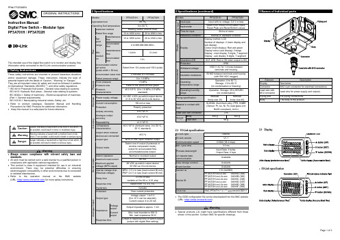
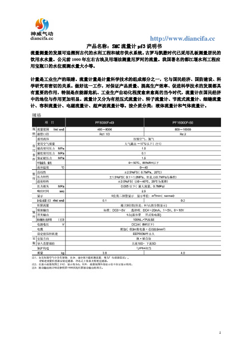
Instruction ManualDigital Flow Switch – Modular type PF3A701H / PF3A702HThe intended use of the digital flow switch is to monitor and display flow information while connected to the IO-Link communication protocol.These safety instructions are intended to prevent hazardous situations and/or equipment damage. These instructions indicate the level of potential hazard with the labels of “Caution,” “Warning” or “Danger.”They are all important notes for safety and must be followed in addition to International Standards (ISO/IEC) *1), and other safety regulations. *1)ISO 4414: Pneumatic fluid power - General rules relating to systems. ISO 4413: Hydraulic fluid power - General rules relating to systems.IEC 60204-1: Safety of machinery - Electrical equipment of machines. (Part 1: General requirements)ISO 10218-1: Manipulating industrial robots -Safety. etc.• Refer to product catalogue, Operation Manual and Handling Precautions for SMC Products for additional information. • Keep this manual in a safe place for future reference.CautionCaution indicates a hazard with a low level of risk which, ifnot avoided, could result in minor or moderate injury.WarningWarning indicates a hazard with a medium level of riskwhich, if not avoided, could result in death or serious injury.DangerDanger indicates a hazard with a high level of risk which, ifnot avoided, will result in death or serious injury.Warning• Always ensure compliance with relevant safety laws and standards.• All work must be carried out in a safe manner by a qualified person in compliance with applicable national regulations.• This product is class A equipment intended for use in an industrial environment. There may be potential difficulties in ensuring electromagnetic compatibility in other environments due to conducted or radiated disturbances.• Refer to the operation manual on the SMC website (URL: https:// ) for more safety instructions.2 Specifications2.1 IO-Link specifications • The IODD configuration file can be downloaded from the SMC website (URL: https:// ).Warning• Special products (-X) might have specifications different from those shown in this section. Contact SMC for specific drawings.Element DescriptionDisplay See belowConnector M12 4-pin connector for electrical connections. Lead wire with M12 connector Lead wire for power supply and outputs. Piping port For piping connections. BodyThe body of the product.3.1 Display• IO-Link specificationORIGINAL INSTRUCTIONSModelsPF3A701H PF3A702H Applicable fluid Air, N 2 Operating fluid temperature0 to 50 o C F l o w Detection method Heating sensor (branch flow) Rated flow range 10 to 1000 L/min 20 to 2000 L/min Set point range Instantaneousflow 10 to 1050 L/min 20 to 2100 L/min Accumulated flow 0 to 999,999,999,990 L Min. resolution Instantaneousflow1 L/min2 L/min Accumulated flow 10 L Accumulated volume per pulse (pulse width = 50 ms) Select from 10 L/pulse and 100 L/pulse Accumulated value hold 2 minutes or 5 minutes P r e s s u r e Rated pressure range 0 to 1.0 MPa Proof pressure 1.5 MPa Pressure loss Refer to the pressure loss graph Pressure Characteristics ±5.0 %F.S. (0 to 1.0 MPa, 0.5 MPa standard) E l e c t r i c a l Power supply voltage 24 VDC ±10% as switch output device21.6 to 30 VDC as IO-Link device Current consumption 150 mA or less Protection Polarity protection A c c u r a c yDisplay accuracy ±3.0 %F.S. Analogue outputaccuracy ±3.0 %F.S.Repeatability ±1.0 %F.S.Temperaturecharacteristics ±5.0 %F.S. (Ambient temp. 0 to 50 o C,25 o C standard)Impact when modular devices are connected ±5.0 %S w i t c h o u t p u tOutput type NPN or PNP open collector output Output mode Select one of output (hysteresis orwindow comparator mode), output for accumulated flow, accumulated pulse output.Switch operation Normal or reversed outputMaximum load current 80 mAMaximum applied voltage (NPN output) 28 VDC as switch output device 30 VDC as IO-Link device Internal voltage drop (Residual voltage) NPN: 1.5 V or less (load current 80 mA) PNP: 2.0 V or less (load current 80 mA)Delay time 3.3 ms or lessvariable at 0 to 60 s / 0.01 step Response time Select from 1 s, 2 s, 5 s.Hysteresis VariableProtection Over current protection A n a l o g u e O u t p u tOutput typeVoltage output: 1 to 5 V (0 to 10 V can be selected), Current output: 4 to 20 mA ImpedanceVoltage output Output impedance approx. 1 kΩ Current outputMax. load impedance 600 Ω Min. load impedance 50 Ω Response timeLinked to response time of switch output(output with digital filter setting)Models PF3A701HPF3A702HE x t . i n p u t Input type Input with no voltage: 0.4 V or less Input mode Select from Reset Accumulated Value, Reset Peak and Reset Bottom valuesTime for input 30 ms or moreD i s p l a y Reference condition Normal or Standard condition Display Display method: LCDNumber of displays: 2 (main display and sub display)Colour (main display): Red and green Display colour (sub display): OrangeDisplay - main display: 5 digits, 7 segment Display - sub display: 6 digits, 7 segment Operation LED OUT LED: Red is ON when output is ONE n v i r o n m e n t a lProtection IP65Withstand voltage 1000 V AC for 1 minute betweenterminals and housing Insulation resistance 50 MΩ between terminals and housing(with 500 VDC megger)Operating temperature range Operation: 0 to 50 o C, Storage: -10 to 60 o C (no condensation or freezing) Operating humidity range Operation, Storage: 35 to 85%RH(no condensation) Piping specification Modular (body size 30)Modular (body size 40)Material in contact with fluid SUS304, Aluminium alloy, PPS, HNBR (Sensor: Pt, Au, Ni, Fe, lead glass (notRoHS compliant), Al 2O 3)Lead wire with connector 3 mWeightBody 350 g400 gLead wire90 gElement DescriptionMain display Displays the instantaneous flow value and error codes. (2 colour display)Operation LED Indicates the output status of OUT.When the output is ON: Orange LED is ON. When the accumulated pulse output mode is selected, the output display will turn off.Sub display Displays the accumulated flow, set value, and peak/ bottom value when in measurement mode.▲ button (UP) Selects the mode and the display shown on theSub display or increases the switch point.S button (SET) Press this button to change the mode and to set a value.▼ button (DOWN) Selects the mode and the display shown on the Sub display or decreases the switch point.Units display (Instantaneous flow) Indicates the flow measurement units currently selected.Units display (Accumulated flow) Indicates the flow measurement units currently selected.IO-Link status indicator light LED is ON when OUT1 is used in IO-Link mode. (LED is OFF in SIO mode)4.1 InstallationWarning•Do not install the product unless the safety instructions have been read and understood.•Use the product within the specified operating pressure and temperature range.4.2 EnvironmentWarning•Do not use in an environment where corrosive gases, chemicals, salt water or steam are present.•Do not use in an explosive atmosphere.•Do not expose to direct sunlight. Use a suitable protective cover. •Do not install in a location subject to vibration or impact in excess of the product’s specifications.•Do not mount in a location exposed to radiant heat that would result in temperatures in excess of the product’s specifications.4.3 Mounting•Never mount the product in a location where it will be used as a mechanical support.•Mount the product so that the fluid flows in the direction indicated by the arrow on the side of the body.•Avoid mounting the product with the display facing upward.•Do not mount the product upside down.•The monitor with integrated display can be rotated. Rotating the display with excessive force will damage the end stop. 4.4 PipingCaution•Before connecting piping make sure to clean up chips, cutting oil, dustetc.•When installing piping or fittings, ensure sealant material does notenter inside the port.•Fit the raised part of the spacer to the recessed part (groove for theraised part) of the product.•Temporarily tighten the retainer A with two hexagon socket head capscrews.•Tighten the two hexagon socket head cap screws with a hexagonalwrench evenly.•Refer to the table below for the screws tightening torque.Applicable modelHex wrench socketnominal sizeTightening torquePF3A701H3 1.2 ±0.05 N•mPF3A702H•The following options are required for coupling with modular F, R, andL combinations. They are separately prepared by the user.Digital flowswitchAircombinationSpacerSpacer withbracketPipe adapterPF3A701H AC30#-D Y300-D Y300T-D E300-#03-DPF3A702H AC40#-D Y400-D Y400T-D E400-#04-D•Refer to the SMC website (URL: https://) for moredetails of options.Caution•Do not apply torsion or bending moment other than the weight of theproduct itself. External piping needs to be supported separately as itmay cause damage. If a moment applied to the equipment isunavoidable during operation, the moment should be lower than themaximum moment shown below. Non-flexible piping like steel tube issusceptible to excessive moment load or vibration. Insert flexible tubesto prevent this.Models PF3A701H PF3A702HMaximum moment (M): N•m 16 19.5Max. moment (M) = Length (L) x Load (F)4.5 WiringCaution•Do not perform wiring while the power supply is ON.•Confirm proper insulation of wiring.•Do not route wires and cables together with power or high voltagecables.The product can malfunction due to interference of noise and surgevoltage from power and high voltage cables. Route the wires of theproduct separately from power or high voltage cables.•If a commercially available switching power supply is used, be sure toground the frame ground (FG) terminal. If the product is connected tothe commercially available switching power supply, switching noise willbe superimposed and the product specifications will not be satisfied.In that case, insert a noise filter such as a line noise filter/ ferritebetween the switching power supplies or change the switching powersupply to the series power supply.Pin numbers ofconnectorWhen used as IO-Link deviceNo. NameWirecolourFunction1 DC(+) Brown 21.6 to 30 VDC2 N.C/Other WhiteNot connected /Analogue output orExternal input3 DC(-) Blue 0 V4 C/Q BlackIO-Link data /Switch output (SIO)5 Function Setting5.1 Function selection modeIn measurement mode, press the SET button for 3 seconds or longer todisplay [F 0].Press the UP or DOWN button to select the function to be changed.Press and hold the SET button for 2 seconds or longer in functionselection mode to return to measurement mode.Refer to the SMC website (URL: https://) for moresetting details.5.1 Default settings∗: Items in brackets are IO-Link specifications.• Flow switch setting and functions • IO-Link functions • Zero cut off functionRefer to the operation manual on the SMC website (URL: https:// ) for setting these functions.Refer to the SMC website (URL: https:// ) for more How to Order details.Refer to the SMC website (URL: https:// ) for details of Outline dimensions..9.1 General MaintenanceCaution• Not following proper maintenance procedures could cause the product to malfunction and lead to equipment damage.• If handled improperly, compressed air can be dangerous.• Maintenance of pneumatic systems should be performed only by qualified personnel.• Before performing maintenance, turn off the power supply and be sure to cut off the supply pressure. Confirm that the air is released to atmosphere.• After installation and maintenance, apply operating pressure and power to the equipment and perform appropriate functional and leakage tests to make sure the equipment is installed correctly.• If any electrical connections are disturbed during maintenance, ensure they are reconnected correctly and safety checks are carried out as required to ensure continued compliance with applicable national regulations.• Do not make any modification to the product.• Do not disassemble the product, unless required by installation or maintenance instructions. • Remove condensate periodically.If condensate enters the secondary side, it can cause operating failure of pneumatic equipment.• Do not use solvents such as benzene, thinner etc. to clean the product. This may damage the surface of the body or erase the markings on the body.Use a soft cloth to remove stains.For heavy stains, use a damp cloth that has been soaked with diluted neutral detergent and fully squeezed, then wipe up the stains again with a dry cloth.• How to reset the product after a power cut or when the power has been unexpectedly removedThe settings of the product are retained from before the power cut or de-energizing.The output condition also recovers to that before the power cut or de-energizing, but may change depending on the operating environment. Therefore, check the safety of the whole system before operating the product.10.1 Limited warranty and Disclaimer/Compliance Requirements Refer to Handling Precautions for SMC Products.This product should not be disposed of as municipal waste. Check your local regulations and guidelines to dispose of this product correctly, in order to reduce the impact on human health and the environment.Refer to or www.smc.eu for your local distributor / importer.URL: https:// (Global) https://www.smc.eu (Europe) SMC Corporation, 4-14-1, Sotokanda, Chiyoda-ku, Tokyo 101-0021, Japan Specifications are subject to change without prior notice from the manufacturer. © 2021 SMC Corporation All Rights Reserved. Template DKP50047-F-085MFunction (Main display) Default Settings (Right sub display) (Main display) (Left sub display) [F 0][rEF ] Select display units [ Std] Standard condition [Uni ] ([Unit]) Units selectionfunction [ L] L/min ([NorP]) Select NPN/PNP ([ PnP]) PNP output [F 1] [oUt ] ([oUt1]) Select output mode[ HYS] Hysteresis mode[ ot ] ([1ot ]) Select switch mode [ P] ([ 1_P]) Normal output[ P] ([P_1 ]) Select input switchoperation[ 500] 500 L/min (PF3A701H) [1000] 1000 L/min (PF3A702H) [ H] ([H_1 ]) Setting of Hysteresis [ 50] 50 L/min (PF3A701H) [ 100] 100 L/min (PF3A702H)([dt1 ]) Delay time setting ([0.00]) 0.00 s [CoL ] Select display colour [ SoG] ([1SoG]) Green when ON Red when OFF (OUT1) ([F 2])[oUt2] Select output mode [ HYS] Hysteresis mode [2ot ] Select switch mode [ 2_P] Normal output [P_2 ] Select input switchoperation [ 500] 500 L/min (PF3A701H) [1000] 1000 L/min (PF3A702H) [H_2 ] Setting of Hysteresis[ 50] 50 L/min (PF3A701H) [ 100] 100 L/min (PF3A702H) [dt2 ] Delay time setting [0.00] 0.00 s [CoL ] Select display colour [1SoG] Green when ONRed when OFF (OUT1)[F 3] [FiL ] Select digital filter[ 1.0] 1 second [F 5] [FnC ] ([FUnC]) Select FUNC (switching analogueoutput/external input)[ oUt] ([AoUt]) Analogueoutput [F10] [SUb ] Select sub display(Line name setting)[ dEF] Default setting [F13] [rEv ] Select Reverse display [ oFF] Reverse display OFF [F14] [CUt ] Select Zero cut-off setting [ 1.0] 1%F.S. cut[F30] [SAv ] ([SAvE]) Accumulated value hold [ oFF] Not stored[F80] [dSP ] ([diSP]) Display OFFmode[ on] Display ON [F81] [Pin ]Security code [ oFF] Not used [F90] [ALL ] Setting of all functions [ oFF] Not used [F96] [Sin ] ([S_in]) Check of input signal [ - - - ] No input signal[F98] [tES ] ([tESt]) Setting ofoutput check[ n] Normal output [F99] [ini ] Reset to the default settings [ oFF] Not used。
关于SMC流量计一般常见的问题及原因分析
关于SMC流量计一般常见的问题及原因分析SMC流量计特别是安装使用在井中的传感器,考虑到湿度大,造成线路板潮湿,也可能造成仪表指示不准或始终无指示常见故障。
正确处理的方式便是定时处理涡街流量计探头、检查接地和屏蔽情况,定时烘干或做防潮正确处理。
1、常见故障情形:新安装使用或检修好的涡街流量计在现场安装使用好后,数显仪表无指示。
原因分析:(1)管道内无流量或流量较小,传感器内无旋涡形成(2)传感器测试敏感度过低(3)探头与管道内部中心有杂质卡着。
2、常见故障情形:管道内无流体流动,而数显仪表有流量显示。
原因分析:(1)仪表接地不良引入外部干扰(2)传感器敏感度太高3、常见故障情形:流量数显仪表摇摆。
原因分析:(1)放大器敏感度调的不符合标准。
(2)流量计安装使用不规范,使通过仪表的介质形成震动。
4、常见故障情形:2次表指示偏低且迟缓。
原因分析:可能是污物堵在了探头与内部中心,但未堵死。
5、常见故障情形:一通电仪表就指示某一刻度,且不管怎么调敏感度电位器都不管用。
原因分析:一般可能是一次表内部某元件损坏。
SMC流量计在使用过程中存在的常见故障分析常见故障情形:指示长时间不准,始终无指示,指示大范围的波动没法读数,指示不回零,小流量时无指示,仪表系数没法判定。
原因分析:1、选型方面的相关问题SMC流量计在口径选型上活在设计选型之后,考虑到工艺条件更改,致使规格选择偏大。
而在实际选型中应选择尽可能小的口径,以提高测量精度。
考虑到选型欠妥可能造成指示长时间不准,指示波动大没法读数。
对于大流量时还可以,小流量时指示不准情形。
2、安装使用方面的相关问题传感器前后面的直管段长度不足,也会造成指示长时间不准。
3、2次仪表的相关问题常见的2次仪表相关问题有电路板有短线之处,量程设定个别位显示坏,K系数设定有个别位置显示坏,使得没法判定量程设定及其他参数的设定,这将使仪表指示不准。
4、回路线路接线相关问题连接头没接好,造成回路停止,使仪表始终无指示5、2次仪表与后续仪表的连接相关问题考虑到后续仪表的相关问题或者后续仪表检修时,使得2次仪表输出的电流信号造成开路,造成2次仪表始终无指示。
气体流量传感器的工作原理
气体流量传感器的工作原理第一篇:气体流量传感器的工作原理气体流量传感器的工作原理气体流量传感器按国际标准化组织IS07145(在环形截面封闭管道中的流体流量测定—在截面一点的速度测量法),采用埋入压电晶体的涡街测速探头,流量传感器插入大口径工业管道内,将卡门旋涡频率转换为与流量成正比的电流或电压脉冲信号或4~20mADC电流信号。
气体流量传感器LUCB型插入式涡街流量计按国际标准化组织IS07145(在环形截面封闭管道中的流体流量测定—在截面一点的速度测量法),气体流量传感器采用埋入压电晶体的涡街测速探头,插入大口径工业管道内,将卡门旋涡频率转换为与流量成正比的电流或电压脉冲信号或4~20毫安电流信号。
第二篇:电磁流量传感器的工作原理电磁流量传感器的工作原理电磁流量传感器是根据法拉第电磁感应定律设计的,在测量管轴线和磁场磁力线相互垂直的管壁上安装一对检测电极,电磁流量传感器当导电液体沿测量管在交变磁场中,与磁力线成垂直方向运动时,flow-meters.c、n导电液体切割磁力线产生感应电动势,电磁流量传感器此感应电动势由测量管上的两个检测电极检出如图1。
用下列公式表示:E=BVD(V)式中:E-感应电动势 VB-磁场的磁通密度 TV-导电液体平均流速 m/sD-导管的内径 m第三篇:流量传感器的具体原理说明流量传感器的具体原理说明流量传感器是由经过现场考验的传感器和壳体组成,流量传感器并应用了具有SSP(频谱信号处理)功能的数字电子技术。
即使是在苛刻的工况条件下,流量传感器也具有高精度和高稳定性。
由于可靠性强,设计合理,数字式旋涡流量计可提高设备的有效率,从而降低生产成本。
基本技术规格流量传感器第四篇:工业化气体流量传感器安装顺序及使用介绍工业化气体流量传感器安装顺序及使用气体流量传感器是依据卡门旋涡原理进行封闭管道流体流量测量的新型流量计。
因其具有良好的介质适应能力,无需温度压力补偿即可直接测量蒸汽、空气、气体、水、液体的工况体积流量,配备温度、压力传感器可测量标况体积流量和质量流量,是节流式流量计的理想替代产品。
mems气体流量

mems气体流量摘要:1.MEMS 气体流量概述2.MEMS 气体流量的工作原理3.MEMS 气体流量的优点4.MEMS 气体流量的应用领域5.MEMS 气体流量的发展前景正文:MEMS 气体流量,全称微机电系统气体流量,是一种利用微机电系统技术制作的气体流量传感器。
MEMS 技术是一种将微型机械和电子技术结合在一起的技术,可以制造出体积微小,功能强大的传感器和执行器。
MEMS 气体流量传感器就是利用这种技术制作的一种流量测量设备。
MEMS 气体流量的工作原理主要是通过测量气体在微通道中的流动来测量气体的流量。
MEMS 气体流量传感器通常由微小的通道和检测元件组成。
当气体流过通道时,会产生一定的压差,这个压差可以通过检测元件检测到,从而得到气体的流量。
MEMS 气体流量具有许多优点,包括高精度、高灵敏度、快速响应、低功耗等。
由于MEMS 气体流量传感器的微型化设计,使其可以实现在线监测和实时控制,大大提高了气体流量的测量精度和效率。
此外,MEMS 气体流量传感器还具有长寿命、抗干扰能力强等优点。
MEMS 气体流量广泛应用于工业、医疗、科学研究等领域。
在工业生产中,MEMS 气体流量传感器可以用于监测和控制气体的流量,以保证生产过程的稳定性和效率。
在医疗领域,MEMS 气体流量传感器可以用于呼吸机的控制和监测,以保证病人的呼吸正常。
在科学研究中,MEMS 气体流量传感器可以用于实验室气体流量的测量和控制。
随着科技的发展,MEMS 气体流量的发展前景广阔。
未来,MEMS 气体流量传感器将会更加微型化和智能化,以满足更多领域的应用需求。
SMC ISA2-GE45N(CH 气动位置传感器)
■使用上的希望
○关于压力开关的选型·使用请遵守以下内容。
●关于选型(请遵守以下有关使用时的安装・ 配线・ 使用环境・ 调整・ 使用・ 维护检查等的内容。) *关于产品规格等 ·请在规定的电压下进行使用。
使用非规定电压时,可能会导致故障·误作动。 规定电压低的话,由于气动位置传感器内部电压下降,可能导致负载不能作动。 请确认负载的作动电压,满足下面的公式。
③ 请参考其他产品个别的保证及免责事项,在理解的基础上使用本产品。
※3) 真空吸盘不适用于使用开始 1 年内的保证期限。 真空吸盘是消耗品,保证期限为购入后 1 年以内。 但是,即使在保证期限内,若因使用而造成磨损或橡胶材质劣化等情况,都不在产品保证的适用范围内。
『适合用途的条件』
出口海外时,请务必遵守经济产业省规定的法令(外国汇兑及外国贸易法)、手续。
※2) 劳动安全卫生法 等
注意: 错误操作时,可能会导致人员受伤,或使物品破损的事项。
警告: 错误操作时,可能使人受到重大伤害甚至死亡的事项。
危险: 在紧迫的危险状态下,如不回避可能使人受到重大伤害甚至死亡的事项。
警告
①请由系统设计者或规格制定者来判断本产品的适合性。 由于在此所述的产品的使用条件多样化,所以请由系统的设计者或规格的制定者来判断系统的适合性。
电源电压 – 气动位置传感器的内部下降电压 ﹥ 负载作动电压
·请在规定的测定流量·使用电压下进行使用。
可能会导致压力开关破损,或不能正常进行计量。
·请不要使用超出最大负载电压及电流的负载。
可能会导致压力开关破损,或寿命缩短。
·请不要使用可能产生冲击电压的负载。
继电器·电磁阀等直接驱动产生冲击电压的负载的情况下,请选用内置吸收冲击电压元件的产品。
气体流量传感器工作原理

气体流量传感器工作原理
气体流量传感器是一种测量流体(气体)流量的装置。
它主要通过测量气体对传感器产生的影响来确定流量大小。
以下是常见的气体流量传感器工作原理的几种类型:
1. 热敏传感器:利用热丝电阻或热膜传感器来测量流体对传感器的冷却效应。
当气体流经传感器时,热敏元件的温度会发生相应的变化,进而测量温度差异来确定流体流量。
2. 低差压传感器:通过测量流体通过管道时产生的压差来间接测量流体流量。
传感器通常包含两个压力传感器,分别位于管道的上下游,并测量两侧的压力差。
3. 筒膜流量计:通过测量气体流经筒膜时的压差来确定流体流量。
筒膜通常由弹性材料制成,当气体通过时,筒膜会发生变形,并产生相应的压差。
4. 质量流量传感器:通过测量单位时间内流体通过传感器的质量来确定流体流量。
传感器利用质量传感器(如热敏电阻)和温度传感器来测量流体的质量变化。
根据质量守恒定律,可以计算出流动的质量。
5. 超声波传感器:利用超声波的传播速度差异来测量气体流量。
传感器通常包含一个发射器和一个接收器,发射器发射超声波脉冲,接收器接收反射的超声波信号。
根据接收到的信号延迟和传播速度,可以计算出气体的流速和流量。
以上是几种常见的气体流量传感器工作原理,不同类型的传感器适用于不同的应用场景,在选择使用时需要结合实际需求进行考虑。
SMC数字式流量计只卖正品PF2MC7102-04-B-M
SMC数字式流量计只卖正品PF2MC7102—04—B—M正品SMC数字式流量开关新款新产品只售原装:smc空气用数字式流量开关,smc流量开关pf2a系列说明书·特地用来监测液体、气体的流速·采用磁性动作,没有机械连接,操作简单可靠。
电子式流量开关/传感器规格:PF2MC7系列3色显示3画面数字式流量开关●适合流体:干燥空气、N2●3色3画面显示●1个产品即可测量广泛的流量范围流量范围比100:1、最小设定单位1L/min●无润滑脂●对应IOLink2色显示式数字式流量传感器PF2M7(L)追加流量范围:2~200L/min配管引出方向:追加后面方向追加流量调整阀(0.05~5L/min)干燥空气、N2、Ar、CO21台可测量广泛的流量,流量范围100:1、最小设定单位0.01L/min对应IOLink耐冷凝水·耐异物性提高小型·轻量无润滑脂2色显示式数字式流量开关PFM可用于空气、N2、Ar、CO2无润滑脂规格。
与流量调整阀一体化。
体积小、重量轻、省空间。
※PFM系列于2023年3月停止生产。
请选择PF2M710/725/750/711系列。
2色显示式数字式流量开关PFMB干燥空气、N2无润滑脂规格与流量调整阀一体化体积小、省空间※PFMB7201系列已于2023年9月停产。
请选择PF2M721系列。
3色显示式数字式流量传感器PF2MC7□(L)适合干燥空气、N23色3画面显示1个产品即可测量广泛的流量范围流量范围比100:1,最小设定单位1L/min无润滑脂对应IOLink3色显示式数字式流量开关/大流量型PF3A□H(L)适合流体:空气, N2流量范围:最大12,000L/min范围本领 100:11台流量开关可计测大范围的流量耐冷凝水、耐异物本领提高压力损失降低75%(20kPa→5kPa)贯穿构造对应IOLink可连接气动组件(模块型)有带4画面压力/温度传感器(模块型)的型号(积累)可同时计测流量/压力/温度正品SMC数字式流量计新款新产品只售原装;正品SMC数字式流量开关新款新产品只售原装SMC数字式流量计PFMC710204BM新款PF2MC710204BM。
- 1、下载文档前请自行甄别文档内容的完整性,平台不提供额外的编辑、内容补充、找答案等附加服务。
- 2、"仅部分预览"的文档,不可在线预览部分如存在完整性等问题,可反馈申请退款(可完整预览的文档不适用该条件!)。
- 3、如文档侵犯您的权益,请联系客服反馈,我们会尽快为您处理(人工客服工作时间:9:00-18:30)。
产品名称:SMC气体流量传感器
传感器(英文名称:transducer/sensor)是一种检测装置,能感受到被测量的信息,并能将感受到的信息,按一定规律变换成为电信号或其他所需形式的信息输出,以满足信息的传输、处理、存储、显示、记录和控制等要求。
传感器的特点包括:微型化、数字化、智能化、多功能化、系统化、网络化。
它是实现自动检测和自动控制的首要环节。
传感器的存在和发展,让物体有了触觉、味觉和嗅觉等感官,让物体慢慢变得活了起来。
通常根据其基本感知功能分为热敏元件、光敏元件、气敏元件、力敏元件、磁敏元件、湿敏元件、声敏元件、放射线敏感元件、色敏元件和味敏元件等十大类。
11。