货车主减速器外文文献翻译、中英文翻译、外文翻译
减速器英文资料及翻译
英文原文:Mineral product monorail reduction gear synopsis1what is reducerReducer is a dynamic communication agencies, the use of gear speed converters, motor rotational speed reducer to the Rotary to be few, and have greater torque institutions.1.1 The reducer role1.1.1 velocity at the same time increase the output torque, torque output ratio by motor output by slowdown, but the attention should be paid to exceed the rated torque reducer. 1.1.2the speed at the same time reduce the inertia load, the inertia of deceleration than reduced to the square. We can look at the General Motors has a value of inertia.1.2 The type of reducerGeneral helical gear reducer has reducer (including parallel shaft helical gear reducer, a worm reducer, bevel gear reducer, etc.), planetary gear reducer, Cycloid reducer, a worm reducer, a planetary friction CVT mechanical machines.1.3 Common reducer1.3.1worm reducer is the main characteristics of a reverse self-locking function, can be larger than a slowdown, input shaft and output shaft axis is not the same, nor in the same plane. But generally larger, transmission efficiency is not high, the accuracy is not high.1.3.2 Harmonic Drive reducer is controllable using flexible components to transfer elastic deformation and dynamic movement, not volume, high precision, but the disadvantage is that flexible wheel limited life, impatient shocks, rigidity and pieces of metal relatively poor. Not too high speed input.1.3.3 planetary reducer its comparative advantage is compact structure, the return gap small, high precision, and have a long life span rated output torque can be done great. However, a price slightly expensive, the requirements of parts before assembly :Rolling cleaning with gasoline, kerosene other parts cleaning. All parts and cabinet not allowed to have any impurities exist. Gear box and the inner wall (Worm), unprocessed surface has not been coated twice erosion-resistant oil paint box has the outer surface coated primer and paint color (color requested by host).Parts coated with a face wash after lubricants.2 the requirements of installation and adjustment2.1Rolling installationRolling bearing inner ring should be installed at the shaft shoulder close to gap must not pass 0.05 mm thick Cypriot feet.2.2Bearing axial clearanceOf the clearance can not be adjusted bearings (such as deep groove ball bearings), axial clearance of 0.25 to 0.4 mm; the clearance adjustable bearing axial clearance numerical table. Click Tapered Roller Bearings axial clearance; angular contact ball bearing axial clearance.2.3Gear (Worm) meshing tooth space availableCypriot side foot of lead or pressure. Will be lead wire on the alveolar, and then turning gear and squash lead wire, measuring two teeth side was crushed lead wire thickness and the size of which is adjacent teeth.2.4 Tooth contact dot cylinder gear tooth contact Dot 2-10-4; bevel gear tooth contact Dot 2-11-4; Gearing contact Dot 2-12-4.3 seal requirements3.1 Box partition between the surface does not allow any pads filled, but can be coated or water glass sealant to ensure that the seal;3.2Assembly, the bolt tightening box, before using 0.05 mm Cypriot-foot inspection Covers Block with me and between the sealing surface;3.3Shaft seal should stretch to smear grease. The seal should be installed in strict accordance with the requirements.4 lubrication requirements4.1 Rationally determine the types of lubricants and greases and grades4.2 Bearing lubrication fat, grease filled in the general Fatliquor space can be 1 / 2 to 2 / 3.4.3 Lubricants should be regularly replaced, the new reducer used for the first time, the operation of oil-7 ~ 14 days, according to the situation can be after every 3 to 6 months for first oil.5 the test requirements5.1 Empty operation: at rated speed is, anti-running 1 to 2 hours;5.2 Load test: at rated speed, rated load operation, the oil temperature balance to date. OnO, bearing the gear reducer, requested the pool temperature is not more than 35 Ctemperature rise no more than 40 C O ; the worm reducer, requested the pool temperature not more than 60C O , bearing temperature of not more than 50 C O .6 packaging and transportation requirements6.1 Protruding shaft and its annex should Oiler packaging;6.2 Handling, lifting may not use screw rings and lug all of the above technical requirements are not necessarily listed, and sometimes also by other projects, mainly by the specific design requirements.7 Technical requirements7.1 Assembly, all parts cleaning with kerosene, gasoline Rolling cleansing, while the existence of any debris. Oil is not painted wall corrosion coatings twice;7.2 Backlash with lead wire mesh test of not less than 0.16 mm, lead wire Backlash may not exceed the smallest of the four times;7.3 Used Tu-color dot test. Tooth high point of contact by not less than 40% of contact spots on teeth not less than 50 per cent. Can be used when necessary, grinding or scraping after grinding to improve contacts;7.4 Bearing axial clearance should be adjusted: φ40 0.05 - 0.1 mm, φ55 0.08 - 0.15 mm;7.5 Test reducer subdivision surface, the contact surface and seal, oil spills are not allowed. Split-Tu allowed to paint or water glass seal and allow the use of any filler;7.6 Engine lubricants to the contents N100 provisions height.8 GEAR INTRODUCTION8.1 Abstract:The important position of the wheel gear can't falter in traditional machine and modern machines.The wheel gear mainly install the direction that delivers the dint at the principal axis box. The passing to process to make them can is divided into many model numbers, used for many situations respectively.8.2 Key words: Wheel gearIn the force analysis of spur gears, the forces are assumed to act in a single plane. We shall study gears in which the forces have three dimensions. The reason for this, in the case of helical gears, is that the teeth are not parallel to the axis of rotation. And in the case of bevel gears, the rotational axes are not parallel to each other. There are also other reasons, as we shall learn.Helical gears are used to transmit motion between parallel shafts. The helix angle is the same on each gear, but one gear must have a right-hand helix and the other a left-hand helix. The shape of the tooth is an involutes helicoids. If a piece of paper cut in the shape of a parallelogram is wrapped around a cylinder, the angular edge of the paper becomes a helix. If we unwind this paper, each point on the angular edge generates an involutes curve. The surface obtained when every point on the edge generates an involutes is called an involutes helicoids.The initial contact of spur-gear teeth is a line extending all the way across the face of the tooth. The initial contact of helical gear teeth is a point, which changes into a line as the teeth come into more engagement. In spur gears the line of contact is parallel to the axis of the rotation; in helical gears, the line is diagonal across the face of the tooth. It is this gradual of the teeth and the smooth transfer of load from one tooth to another, which give helical gears the ability to transmit heavy loads at high speeds. Helical gears subject the shaft bearings to both radial and thrust loads. When the thrust loads become high or are objectionable for other reasons, it may be desirable to use double helical gears. A double helical gear (herringbone) is equivalent to two helical gears of opposite hand, mounted side by side on the same shaft. They develop opposite thrust reactions and thus cancel out the thrust load. When two or more single helical gears are mounted on the same shaft, the hand of the gears should be selected so as to produce the minimum thrust load.Crossed-helical, or spiral, gears are those in which the shaft centerlines are neither parallel nor intersecting. The teeth of crossed-helical fears have point contact with each other, which changes to line contact as the gears wear in. For this reason they will carry out very small loads and are mainly for instrumental applications, and are definitely not recommended for use in the transmission of power. There is on difference between a crossed helical gear and a helical gear until they are mounted in mesh with each other. They are manufactured in the same way. A pair of meshed crossed helical gears usually have the same hand; that is, a right-hand driver goes with a right-hand driven. In the design of crossed-helical gears, the minimum sliding velocity is obtained when the helix angle are equal. However, when the helix angle is not equal, the gear with the larger helix angle should be used as the driver if both gears have the same hand.Worm gears are similar to crossed helical gears. The pinion or worm has a small numberof teeth, usually one to four, and since they completely wrap around the pitch cylinder theyare called threads. Its mating gear is called a worm gear, which is not a true helical gear. A worm and worm gear are used to provide a high angular-velocity reduction between nonintersecting shafts which are usually at right angle. The worm gear is not a helical gear because its face is made concave to fit the curvature of the worm in order to provide line contact instead of point contact. However, a disadvantage of worm gearing is the high sliding velocities across the teeth, the same as with crossed helical gears.Worm gearing are either single or double enveloping. A single-enveloping gearing is one in which the gear wraps around or partially encloses the worm.. A gearing in which each element partially encloses the other is, of course, a double-enveloping worm gearing. The important difference between the two is that area contact exists between the teeth of double-enveloping gears while only line contact between those of single-enveloping gears. The worm and worm gear of a set have the same hand of helix as for crossed helical gears, but the helix angles are usually quite different. The helix angle on the worm is generally quite large, and that on the gear very small. Because of this, it is usual to specify the lead angle on the worm, which is the complement of the worm helix angle, and the helix angleon the gear; the two angles are equal for a 90-deg. Shaft angle.中文译文:1 什么是减速器减速器是一种动力传达机构,利用齿轮的速度转换器,将马达的回转数减速到所要的回转数,并得到较大转矩的机构。
驱动桥和差速器外文文献翻译、中英文翻译、外文翻译

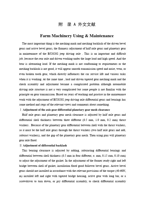
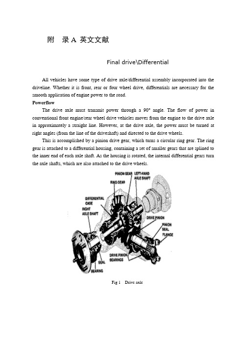
附录A 英文文献Drive axle/differentialAll vehicles have some type of drive axle/differential assembly incorporated into the driveline. Whether it is front, rear or four wheel drive, differentials are necessary for the smooth application of engine power to the road.PowerflowThe drive axle must transmit power through a 90°angle. The flow of power in conventional front engine/rear wheel drive vehicles moves from the engine to the drive axle in approximately a straight line. However, at the drive axle, the power must be turned at right angles (from the line of the driveshaft) and directed to the drive wheels.This is accomplished by a pinion drive gear, which turns a circular ring gear. The ring gear is attached to a differential housing, containing a set of smaller gears that are splined to the inner end of each axle shaft. As the housing is rotated, the internal differential gears turn the axle shafts, which are also attached to the drive wheels.Fig 1 Drive axleRear-wheel driveRear-wheel-drive vehicles are mostly trucks, very large sedans and many sports car and coupe models. The typical rear wheel drive vehicle uses a front mounted engine and transmission assemblies with a driveshaft coupling the transmission to the rear drive axle. Drive in through the layout of the bridge, the bridge drive shaft arranged vertically in the same vertical plane, and not the drive axle shaft, respectively, in their own sub-actuator with a direct connection, but the actuator is located at the front or the back of the adjacent shaft of the two bridges is arranged in series. Vehicle before and after the two ends of the driving force of the drive axle, is the sub-actuator and the transmission through the middle of the bridge. The advantage is not only a reduction of the number of drive shaft, and raise the driving axle of the common parts of each other, and to simplify the structure, reduces the volume and quality.Fig 2 Rear-wheel-drive axleSome vehicles do not follow this typical example. Such as the older Porsche or Volkswagen vehicles which were rear engine, rear drive. These vehicles use a rear mounted transaxle with halfshafts connected to the drive wheels. Also, some vehicles were produced with a front engine, rear transaxle setup with a driveshaft connecting the engine to the transaxle, and halfshafts linking the transaxle to the drive wheels.Differential operationIn order to remove the wheel around in the kinematics due to the lack of co-ordination about the wheel diameter arising from a different or the same rolling radius of wheel travel required, inter-wheel motor vehicles are equipped with about differential, the latter to ensure that the car driver Bridge on both sides of the wheel when in range with a trip to the characteristics of rotating at different speeds to meet the requirements of the vehicle kinematics.Fig 3 Principle of differentialThe accompanying illustration has been provided to help understand how this occurs.1.The drive pinion, which is turned by the driveshaft, turns the ring gear.2.The ring gear, which is attached to the differential case, turns the case.3.The pinion shaft, located in a bore in the differential case, is at right angles to the axle shafts and turns with the case.4.The differential pinion (drive) gears are mounted on the pinion shaft and rotate with the shaft .5.Differential side gears (driven gears) are meshed with the pinion gears and turn with the differential housing and ring gear as a unit.6.The side gears are splined to the inner ends of the axle shafts and rotate the shafts asthe housing turns.7.When both wheels have equal traction, the pinion gears do not rotate on the pinion shaft, since the input force of the pinion gears is divided equally between the two side gears.8.When it is necessary to turn a corner, the differential gearing becomes effective and allows the axle shafts to rotate at different speeds .Open-wheel differential on each general use the same amount of torque. To determine the size of the wheel torque to bear two factors: equipment and friction. In dry conditions, when a lot of friction, the wheel bearing torque by engine size and gear restrictions are hours in the friction (such as driving on ice), is restricted to a maximum torque, so that vehicles will not spin round. So even if the car can produce more torque, but also need to have sufficient traction to transfer torque to the ground. If you increase the throttle after the wheels slip, it will only make the wheels spin faster.Fig 4 Conventional differentialLimited-slip and locking differential operationFig 5 Limited-slip differentialDifferential settlement of a car in the uneven road surface and steering wheel-driven speed at about the different requirements; but is followed by the existence of differential in the side car wheel skid can not be effective when the power transmission, that is, the wheel slip can not produce the driving force, rather than spin the wheel and does not have enough torque. Good non-slip differential settlement of the car wheels skid on the side of the power transmission when the issue, that is, locking differential, so that no longer serve a useful differential right and left sides of the wheel can be the same torque.Limited-slip and locking differential operation can be divided into two major categories:(1) mandatory locking type in ordinary differential locking enforcement agencies to increase, when the side of the wheel skid occurs, the driver can be electric, pneumatic or mechanical means to manipulate the locking body meshing sets of DIP Shell will be with the axle differential lock into one, thus the temporary loss of differential role. Relatively simple structure in this way, but it must be operated by the driver, and good roads to stop locking and restore the role of differential.(2) self-locking differential installed in the oil viscosity or friction clutch coupling, whenthe side of the wheel skid occurs when both sides of the axle speed difference there,coupling or clutch friction resistance on the automatic, to make certain the other side of the wheel drive torque and the car continued to travel. When there is no speed difference on both sides of the wheel, the frictional resistance disappeared, the role of automatic restoration of differentials. More complicated structure in this way, but do not require drivers to operate. Has been increasingly applied in the car. About non-slip differential, not only used for the differential between the wheels, but also for all-wheel drive vehicle inter-axle differential/.Gear ratioThe drive axle of a vehicle is said to have a certain axle ratio. This number (usually a whole number and a decimal fraction) is actually a comparison of the number of gear teeth on the ring gear and the pinion gear. For example, a 4.11 rear means that theoretically, there are 4.11 teeth on the ring gear for each tooth on the pinion gear or, put another way, the driveshaft must turn 4.11 times to turn the wheels once. The role of the final drive is to reduce the speed from the drive shaft, thereby increasing the torque. Lord of the reduction ratio reducer, a driving force for car performance and fuel economy have a greater impact. In general, the more reduction ratio the greater the acceleration and climbing ability, and relatively poor fuel economy. However, if it is too large, it can not play the full power of the engine to achieve the proper speed. The main reduction ratio is more Smaller ,the speed is higher, fuel economy is better, but the acceleration and climbing ability will be poor.附录B 文献翻译驱动桥和差速器所有的汽车都装有不同类型的驱动桥和差速器来驱动汽车行驶。
中英文文献翻译-减速器和差速器的调整与装配
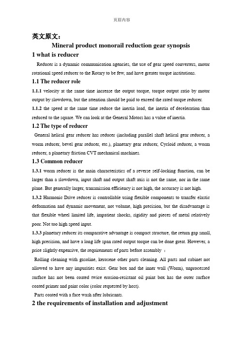
附录 A 外文文献Farm Machinery Using & MaintenanceThe most important thing is the meshing mark and meshing backlash of the driven bevel gears and active bevel gears, the firmness adjustment of half axle gears and planetary gear in maintenance of the BJ2020S jeep driving axle . This is an important and difficult job ,because the rear axle and driven working under the large load and high speed. And the bear is alternating load. If the meshing mark is not conforming to requirements or the meshing backlash is not good, it will appear smooth transmission speed and noise, wear, or even broken tooth gear, which directly influences the car service life and various tasks when it is working. At the same time , lord and driven tapered gear meshing mark and the check assembly and adjustment became a complicated problem although automobile driving axle structure is not a very complicated but some people is not familiar with the principle on gear transmission. Based on years of teaching and practice in the maintenance work with the adjustment of BJ2020S jeep driving axle differential gears and bearings has some method and steps of the relevant views and comments about something.ⅠAdjustment of the axis gear differential planetary gear mesh clearanceHalf axle gears and planetary gear mesh clearance is adjusted by half axle gears and differential shell thickness between three different (0.5 mm, 1.0 mm, 0.2 mm) thrust washers . Because of the planetary gear differential between shell with the thrust washers, so it must be the half axle gears through the thrust washers (two half axle gears and add, subtract washers), and the gap of the planetary gear mesh. Then using pins will planetary gear axle fixed.ⅡAdjustment of differential backlashThis bearing clearance is adjusted by adding, subtracting differential bearings and differential between shell thickness (0.5 mm in four different, o. mm, 0.15 ram, 0.10 ram) to adjust the adjustment of the gasket. In the adjustment of the former ready right and left bridge between shell of gasket, installation fixed good follower bevel gears. Active bevel gears should not installed in accordance with the relevant provisions of the torque (40-60N, m) installed left and right with tapered bridge housing, active gear with long bar, or a screwdriver to turn down, or pry differential assembly, to check differential assemblybearings between differential to feel no axial clearance and rotate freely.ⅢActive bevel gears bearing clearance adjustmentIn active position of bevel gears can be determined by the basic, increase and decrease active bevel gears with active before bearings taper gear bearing thrust ring between four different thickness (0.10 mm, 0.15 ram, 0.25 mm mm) adjustment, 0.50 gasket to adjust, the flexible rotation, no axial and radial clearance.ⅣActive bevel gears and driven bevel gears clearance and meshing mark adjustment Domestic automobile gear for no modifier, assembling widely adopted, the first meshing mark check whether the meshing mark requirements, such as requirements, through the change of bevel gears, driven axial position to get to meet the requirements of meshing mark, the active bevel gears bearing and differential bearing clearance (pre-tightening degrees) basis, rub-up, driven bevel gears, initiative on 3-4 taper gear teeth are coated with thin layer opposite, oil (or face turns into oil), according to the requirements and differential assembly installed left, right, forward and backward bridge housing, then turn active bevel gears decomposition of left and right to bridge housing, driven gear tooth surface of conical whether imprint requirements. If meshing mark requirements, visible to the situation by outward, to the right or left, bevel gears, driven to adjust. When the meshing mark to tooth root cap, the main, small or client, the formula for the Lord: "the Lord, from (i.e., big into bevel gears into active driven gear), small (i.e. driven out from bevel gears removed from active gear)." When the Lord, driven gear cone of meshing mark complies with the standards and inspection, driven bevel gears, active bevel gears and clearance of bevel gears driven backlash should actively bevel gears in the radius of 45mm flanges on the circumference displacement measurement, the arc length) should be in (0.2-0.6 mm. If does not accord with a standard, can increase and decrease active bevel gears and bearings taper gear after the shim between left and right or mobile differential bearing adjustment gasket, driven to adjust the gap, so bevel gears, driven when the bevel gears has adjusted, adjust the marks are not destroyed, small volume, driven tapered gear meshing mark.ⅤDrive and differential assemblyWe can start assemble the drive and differential when the differential gears, driven gear, each bearing, tapered meshing mark adjustment is over. Based on the thickness of the gasket and the bolt torques, we should coated with rubber seal, assembled active bevelgears, mount differential assembly, then closed the bridge housing.附录 B 中文译文减速器和差速器的调整与装配在对BJ2020S吉普车后桥的维修中,最主要的就是减速器主、从动圆锥齿轮的啮合印痕及啮合间隙;差速器半轴齿轮、行星齿轮啮合间隙和各轴承松紧度的调整。
中英文文献翻译—重型卡车主减速器

附录ATruck Main Reduction Gear In the highly competitive period following the energy crisis of the early 1970's, the automotive industry had to shift attention increasingly towards improvement of the quality of the product, yet still keeping its prices as low as possible. Prior to that GKN Axles Ltd, to take optimum advantage of economies of scale, had been producing at highly competitive prices a standard range of axles of different types and sizes, from which all customers' needs could be satisfied. Because vehicle manufacturers had not hitherto had to place such a great emphasis on fuel economy, and therefore on light weight, these standard axles could cater reliably for all conditions likely to be met in a wide variety of applications. Now vehicle manufacturers require axles designed and developed for their specific applications. As axle design is becoming increasingly specialised, customers are increasingly raising their aspirations in terms of performance an reliability. For this reason, they are turning to specialists such as GKN Axles Ltd who have the ability to provide axles for a wide variety of vehicles。
汽车主减速器外文文献翻译、中英文翻译、外文翻译

汽车主减速器外文文献翻译、中英文翻译、外文翻译AUTOMOTIWE FINAL DRIVEFINAL DRIVEA final drive is that part of a power transmission system between the drive shaft and the differential. Its function is to change the direction of the power transmitted by the drive shaft through 90 degrees to the driving axles. At the same time. it provides a fixed reduction between the speed of the drive shaft and the axle driving the wheels.The reduction or gear ratio of the final drive is determined by dividing the number of teeth on the ring gear by the number of teeth on the pinion gear. In passenger vehicles, this speed reduction varies from about 3:1 to 5:1. In trucks it varies from about 5:1 to 11:1. To calculate rear axle ratio, count the number of teeth on each gear. Then divide the number of pinion teeth into the number of ring gear teeth. For example, if the pinion gear has 10 teeth and the ring gear has 30 (30 divided by 10), the rear axle ratio would be 3:1. Manufacturers install a rear axle ratio that provides a compromise between performance and economy. The average passenger car ratio is 3.50:1.The higher axle ratio, 4.11:1 for instance, would increase acceleration and pulling power but would decrease fuel economy. The engine would have to run at a higher rpm to maintain an equal cruising speed.The lower axle ratio. 3:1, would reduce acceleration and pulling power but would increase fuel mileage. The engine would run at a lower rpm while maintaining the same speed.The major components of the final driveinclude the pinion gear, connected to the drive shaft, and a bevel gear or ring gearthat is bolted or riveted to the differential carrier. To maintain accurate and proper alignment and tooth contact, the ring gear and differential assembly are mounted in bearings. The bevel drive pinion is supported by two tapered roller bearings, mounted in the differential carrier. This pinion shaft is straddle mounted. meaning that a bearing is located on each side of the pinion shaft teeth. Oil seals prevent the loss of lubricant from the housing where the pinion shaft and axle shafts protrude. As a mechanic, you willencounter the final drive gears in the spiral bevel and hypoid design.Spiral Bevel GearSpiral bevel gears have curved gear teeth with the pinion and ring gear on the same center line. This type of final drive is used extensively in truck and occasionally in older automobiles. This design allows for constant contact between the ring gear and pinion. It also necessitates the use of heavy grade lubricants.Hypoid GearThe hypoid gear final drive is an improvement or variation of the spiral bevel design and is commonly used in light and medium trucks and all domestic rear- wheel drive automobiles. Hypoid gears have replaced spiral bevel gears because they lower the hump in the floor of the vehicle and improve gear-meshing action. As you can see in figure 5-13, the pinion meshes with the ring gear below the center line and is at a slight angle (less than 90 degrees).Figure 5-13.—Types of final drives.This angle and the use of heavier (larger) teeth permit an increased amount of power to be transmitted while the size of the ring gear and housing remain constant. The tooth design is similar to the spiral bevel but includes some of thecharacteristics of the worm gear. This permits the reduced drive angle. The hypoid gear teeth have a more pronounced curve and steeper angle, resulting in larger tooth areas and more teeth to be in contact at the same time. With more than one gear tooth in contact, a hypoid design increases gear life and reduces gear noise. The wiping action of the teeth causes heavy tooth pressure that requires the use of heavy grade lubricants.Double-Reduction Final DriveIn the final drives shown in figure 5-13, there is a single fixed gear reduction. This is the only gear reduction in most automobiles and light- and some medium-duty trucks between the drive shaft and the wheels.Double-reduction final drives are used for heavy- duty trucks. With this arrangement (fig. 5-14) it is not necessary to have alarge ring gear to get the necessary gear reduction. The first gear reduction is obtained through a pinion and ring gear as the single fixed gear reduction final drive. Referring to figure 5-14, notice that the secondary pinion is mounted on the primary ring gear shaft. The second gear reduction is the result of the secondary pinion which is rigidly attached to the primary ring gear, driving a large helical gear which is attached to the differential case. Double-reduction final drives may be found on military design vehicles, such as the 5-ton truck. Many commercially designed vehicles of this size use a single- or double-reduction final drive with provisions for two speeds to be incorporatedFigure 5-14.—Double-reduction final driveTwo-Speed Final DriveThe two-speed or dual-ratio final drive is used to supplement the gearing of the other drive train components and is used in vehicles with a single drive axle (fig. 5-15). The operator can select the range or speed of this axle with a button on the shifting lever of the transmission or by a lever through linkage The two-speed final drive doubles the number of gear ratios available for driving the vehicle under various load and road conditions. For example, a vehicle with a two-speed unit and a five-speed transmission, ten different forward speeds are available. This unit provides a gear ratio high enough to permit pulling a heavy load up steep grades and a low ratio to permit the vehicle to run at high speeds with a light load or no load The conventional spiral bevel pinion and ring gear drives the two-speed unit, but aplanetary gear train is placed between the differential drive ring gear and the differential case. The internal gear of the planetary gear train is bolted rigidly to the bevel drive gear. A ring on which the planetary gears are pivoted is bolted to the differential case. A member, consisting of the sun gear and a dog clutch, slides on one of the axle shafts and is controlled through a button or lever accessible to the operatorWhen in high range, the sun gear meshes with the internal teeth on the ring carrying the planetary gears and disengages the dog clutch from the left bearing adjusting ring, which is rigidly held in the differential carrier. In this position, the planetary gear train is locked together. There is no relative motion between the differential case and the gears in the planetary drive train. The differential case is driven directly by the differential ring gear, the same as in the conventional single fixed gear final drive.When shifted into low range, the sun gear is slid out of mesh with the ring carrying the planetary gears. The dog clutch makes a rigid connection with the left bearing adjusting ring. Because the sun gear is integral with the dog clutch, it is also locked to the bearing adjusting rings and remains stationary. The internal gear rotates the planetary gears around the stationary sun gear, and the differential case is driven by the ring on which the planetary gears are pivoted. This action produces the gear reduction, or low speed, of the axleDIFFERENTIAL ACTIONThe rear wheels of a vehicle do not always turn at the same speed. When the vehicle is turning or when tire diameters differ slightly, the rear wheels must rotate at different speeds.If there were a solid connection between each axle and the differential case, the tires would tend to slide, squeal, and wear whenever the operator turned the steering wheel of the vehicle.A differential is designed to prevent this problem.Driving Straight AheadWhen a vehicle is driving straight ahead, the ring gear, the differential case, the differential pinion gears, and the differential side gears turn as a unit. The two differential pinion gears do NOT rotate on the pinion shaft, because they exert equal force on the side gears. As a result, the side gears turn at the same speed as the ring gear, causing both rear wheels to turn at the same speed.Turning CornersWhen the vehicle begins to round a curve, the differential pinion gears rotate on the pinion shaft. This occurs because the pinion gears must walk around the slower turning differential side gear. Therefore, the pinion gears carry additional rotary motion to the faster turning outer wheel on the turn..Differential speed is considered to be 100 percent. The rotating action of the pinion gears carries 90 percent of this speed to the slowing mover inner wheel and sends 110 percent of the speed to the faster rotating outer wheel. This action allows the vehicle to make the turn without sliding or squealing the wheels.Figure 5-15.—Two speed final drive汽车主减速器主减速器主减速器是在传动轴和差速器之间的一个动力传动系统的组成部分。
减速器论文中英文对照资料外文翻译文献

减速器论文中英文对照资料外文翻译文献What is a Gearbox?A XXX.1.The n of a Gearbox1) The gearbox ces the speed while increasing the output torque。
The torque output。
is the motor output multiplied by the n。
but it should not exceed the XXX.2) The gearbox also ces the inertia of the load。
which decreases by the square of the n。
Most motors have an inertia value that can be XXX.2.Types of GearboxesCommon gearboxes include bevel gear cers (including parallel-axis bevel gear cers。
worm gear cers。
and cone gear cers)。
ary gear cers。
cycloid cers。
worm gear cers。
XXX.mon Gearboxes1) The main feature of the worm gear cer is its reverse self-locking n。
which can achieve a large n。
The input and output shafts are not on the same axis or in the same plane。
However。
it generally has a large volume。
low n efficiency。
and low n.2) XXX and power。
It has a small size and high n。
汽车变速器的设计外文文献翻译、中英文翻译、外文翻译

本科毕业设计(论文)英文资料翻译*****指导教师:孙飞豹(副教授)学科、专业:车辆工程沈阳理工大学应用技术学院2011年12月20日transmission used in automobilesA standard transmission or manual transmission is the traditional type of transmission used in automobiles. The manual or standard transmission consists of a series of gears, synchros, roller bearings, shafts and gear selectors. The main clutch assembly is used to engage and disengage the engine from the transmission. Heliacal cut gears are used to select the ratio desired the sector fork move gears from one to another by using the gearshift knob. Synchros are used to slow the gear to a stop before it is engaged to avoid gear grinding, the counter shaft hold the gears in place and against the main input and output shaft. A stick shift transmission has no torque converter so there is no need for a transmission cooler. A stick shift transmission needs a simple fluid change for proper service. (there is no transmission filter in a stick shift transmission).Transmission ShifterMost manual transmissions have one reverse gear and four to six forward gears. Some cars also have eight forward gears while thirteen to twenty-four gears are present in semi trucks. To differentiate among the available standard transmissions, they are addressed by the number of forward gears. For example, if the standard transmission has five gears, it will be referred to as 5-speed standard transmission or 5-speed standard.Typical Standard Transmission ConfigurationInside the transmission shafts contain all forward and reverse gears. Most transmissions contain three shafts: input shaft, output shaft and counter or lay shaft. Other than standard transmission, there are other transmissions like continuously variable transmission, automatic transmission and semi-automatic transmission. In the manual transmission, a pair of gears inside the transmission selects the gear ratios. Whereas, in an automatic transmission, combination of brake bands and clutch packs control the planetary gear which selects the gear ratio.If there is a provision to select a gear ratio manually in automatic transmissions, the system is called a semi-automatic transmission. The driver can select from any of the gears at any pointof time. In some automobiles like racing cars and motorcycles that have standard transmissions, the driver can select the preceding or the following gear ratio with no clutch operation needed. This type of standard transmission is known as sequential transmission. In this transmission the clutch is still used for initial take off.Clutch and Flywheel AssemblyThe main clutch plays the role of a coupling device which separates the transmission and the engine. If the clutch is absent and the car comes to a stop the engine will stall. In automobiles, the clutch can be operated with the help of a pedal located on the floor of the vehicle. In an automatic transmission instead of a clutch, a torque converter is used to separate the transmission and engine.Typical Stick Shift PatternsA desired gear can be selected by a lever which is usually located on the floor in between the driver and passenger seat. This selector lever is called the gear lever or gear selector or gear shift or shifter. This gear stick can be made to move in right, left, forward and backward direction. When the gear is placed on the N position or neutral position, no gear will be selected. To move the car in the backward direction, the R gear or reverse gear should be selected.Standard transmissions are more efficient and less expensive to produce than automatic transmissions. A Standard transmission is about 15% more efficient compared to an automatic transmission. Standard transmissions are generally stronger than automatic transmissions and off road vehicles take advantage of a direct gear selection so they can withstand rough conditions. Less active cooling is also required in manual transmission system because less power is wasted.●Popular Problem ChecksCar will not go into gearClutch disc is broken completelyInternal transmission damageFailed clutch master cylinderSeized clutch slave cylinderBroken clutch fork pivotBroken clutch cableCar goes into gear but it fades out or is slippingClutch is worn out and needs replacementClutch is oil soaked from a external engine oil leakCar makes grinding noise while operating or shifting gearsOne of the roller or thrust bearings has failedThe gear synchro is worn out not forcing the gear stop before it is engaged causing a grinding gear.A counter or main shaft bearing has failed causing misalignment of the gears●Troubleshooting Noise and ProblemsIf the vehicle is running and a whirring sound is heard, then it goes away when the clutch is depressed, the transmission input bearing has failed.If the transmission is quiet in neutral but when you depress the clutch a squeaking noise is observed, a clutch throw out bearing has failed.Tips:Never let little noises go unattended; a small noise can cause a large noise and transmission operation failure. Never overload a vehicle or tow beyond the capacity this can cause premature transmission failure.汽车变速器汽车传统变速器是那种标准的手动变速器。
中英文文献翻译-主减速器和差速器
附录A 英文文献Final drive\DifferentialAll vehicles have some type of drive axle/differential assembly incorporated into the driveline. Whether it is front, rear or four wheel drive, differentials are necessary for the smooth application of engine power to the road.PowerflowThe drive axle must transmit power through a 90°angle. The flow of power in conventional front engine/rear wheel drive vehicles moves from the engine to the drive axle in approximately a straight line. However, at the drive axle, the power must be turned at right angles (from the line of the driveshaft) and directed to the drive wheels.This is accomplished by a pinion drive gear,which turns a circular ring gear. The ring gear is attached to a differential housing, containing a set of smaller gears that are splined to the inner end of each axle shaft. As the housing is rotated, the internal differential gears turn the axle shafts, which are also attached to the drive wheels.Fig 1 Drive axleRear-wheel driveRear-wheel-drive vehicles are mostly trucks, very large sedans and many sports car and coupe models. The typical rear wheel drive vehicle uses a front mounted engine and transmission assemblies with a driveshaft coupling the transmission to the rear drive axle. Drive in through the layout of the bridge, the bridge drive shaft arranged vertically in the same vertical plane, and not the drive axle shaft, respectively, in their own sub-actuator with a direct connection, but the actuator is located at the front or the back of the adjacent shaft of the two bridges is arranged in series. Vehicle before and after the two ends of the driving force of the drive axle, is the sub-actuator and the transmission through the middle of the bridge. The advantage is not only a reduction of the number of drive shaft, and raise the driving axle of the common parts of each other, and to simplify the structure, reduces the volume and quality.Fig 2 Rear-wheel-drive axleSome vehicles do not follow this typical example. Such as the older Porsche or Volkswagen vehicles which were rear engine, rear drive. These vehicles use a rear mounted transaxle with halfshafts connected to the drive wheels. Also, some vehicles were produced with a front engine, rear transaxle setup with a driveshaft connecting the engine to the transaxle, and halfshafts linking the transaxle to the drive wheels.Differential operationIn order to remove the wheel around in the kinematics due to the lack of co-ordination about the wheel diameter arising from a different or the same rolling radius of wheel travel required, inter-wheel motor vehicles are equipped with about differential, the latter to ensure that the car driver Bridge on both sides of the wheel when in range with a trip to the characteristics of rotating at different speeds to meet the requirements of the vehicle kinematics.Fig 3 Principle of differentialThe accompanying illustration has been provided to help understand how this occurs.1.The drive pinion, which is turned by the driveshaft, turns the ring gear.2.The ring gear, which is attached to the differential case, turns the case.3.The pinion shaft, located in a bore in the differential case, is at right angles to the axle shafts and turns with the case.4.The differential pinion (drive) gears are mounted on the pinion shaft and rotate with the shaft .5.Differential side gears (driven gears) are meshed with the pinion gears and turn with the differential housing and ring gear as a unit.6.The side gears are splined to the inner ends of the axle shafts and rotate the shafts as the housing turns.7.When both wheels have equal traction, the pinion gears do not rotate on the pinion shaft, since the input force of the pinion gears is divided equally between the two side gears.8.When it is necessary to turn a corner, the differential gearing becomes effective and allows the axle shafts to rotate at different speeds .Open-wheel differential on each general use the same amount of torque. To determine the size of the wheel torque to bear two factors: equipment and friction. In dry conditions, when a lot of friction, the wheel bearing torque by engine size and gear restrictions are hours in the friction (such as driving on ice), is restricted to a maximum torque, so that vehicles will not spin round. So even if the car can produce more torque, but also need to have sufficient traction to transfer torque to the ground. If you increase the throttle after the wheels slip, it will only make the wheels spin faster.Fig 4 Conventional differentialLimited-slip and locking differential operationFig 5 Limited-slip differentialDifferential settlement of a car in the uneven road surface and steering wheel-driven speedat about the different requirements; but is followed by the existence of differential in the side car wheel skid can not be effective when the power transmission, that is, the wheel slip can not produce the driving force, rather than spin the wheel and does not have enough torque. Good non-slip differential settlement of the car wheels skid on the side of the power transmission when the issue, that is, locking differential, so that no longer serve a useful differential right and left sides of the wheel can be the same torque.Limited-slip and locking differential operation can be divided into two major categories:(1) mandatory locking type in ordinary differential locking enforcement agencies to increase, when the side of the wheel skid occurs, the driver can be electric, pneumatic or mechanical means to manipulate the locking body meshing sets of DIP Shell will be with the axle differential lock into one, thus the temporary loss of differential role. Relatively simple structure in this way, but it must be operated by the driver, and good roads to stop locking and restore the role of differential.(2) self-locking differential installed in the oil viscosity or friction clutch coupling, when the side of the wheel skid occurs when both sides of the axle speed difference there, coupling or clutch friction resistance on the automatic, to make certain the other side of the wheel drive torque and the car continued to travel. When there is no speed difference on both sides of the wheel, the frictional resistance disappeared, the role of automatic restoration of differentials. More complicated structure in this way, but do not require drivers to operate. Has been increasingly applied in the car. About non-slip differential, not only used for the differential between the wheels, but also for all-wheel drive vehicle inter-axle differential/.Gear ratioThe drive axle of a vehicle is said to have a certain axle ratio. This number (usually a whole number and a decimal fraction) is actually a comparison of the number of gear teeth on the ring gear and the pinion gear. For example, a 4.11 rear means that theoretically, there are 4.11 teeth on the ring gear for each tooth on the pinion gear or, put another way, the driveshaft must turn 4.11 times to turn the wheels once. The role of the final drive is to reduce the speed from the drive shaft, thereby increasing the torque. Lord of the reduction ratio reducer, a driving force for car performance and fuel economy have a greater impact. In general, the more reduction ratio the greater the acceleration and climbing ability, and relatively poor fuel economy. However, if it is too large, it can not play the full power of the engine to achieve the proper speed. The main reduction ratio is more Smaller ,the speed is higher, fuel economy is better, but the acceleration and climbing ability will be poor.附录B 文献翻译主减速器和差速器所有的汽车都装有不同类型的主减速器和差速器来驱动汽车行驶。
- 1、下载文档前请自行甄别文档内容的完整性,平台不提供额外的编辑、内容补充、找答案等附加服务。
- 2、"仅部分预览"的文档,不可在线预览部分如存在完整性等问题,可反馈申请退款(可完整预览的文档不适用该条件!)。
- 3、如文档侵犯您的权益,请联系客服反馈,我们会尽快为您处理(人工客服工作时间:9:00-18:30)。
纵向水平布置可以使总成的垂向轮廓尺寸减小,使汽车减速器的整体尺寸在水平方向上减小,从而降低汽车的质心高度,但与此同时使纵向尺寸增加使汽车变得更宽,但这种缺点在不同的汽车上使用可以变劣势为优势,当用在长轴距汽车上时可适当减小传动轴的长度,但不利于短轴距汽车的总布置,如果布置在短轴距汽车上会使传动轴过于短,导致万向传动轴的夹角加大。垂向布置的减速器可以使驱动桥的纵向尺寸减小,与此同时可减小万向传动轴的夹角,但由于这种垂向布置的主减速器壳固定在桥壳的上方,这种布置形式不仅使垂向轮廓尺寸增大,而且降低了桥壳的刚度,这种垂向布置形式不利于齿轮工作。但是这种布置形式也有他的优势,虽然这种布置降低了桥壳的刚度不利于齿轮工作,但是可便于贯通式驱动桥的布置。而斜向布置对传动轴布置和提高桥壳刚度都有利,可以说是具有了垂直布置形式和纵向布置形式的优点。
现在的重点是选择合理化的材料,方法和内容途径。总的改革是必要的,对于复杂性很大的现代化汽车,需要考虑总体的效率,紧凑性,汽车的质量要轻,考虑汽车的可靠性,汽车的耐用性,汽车的完善性以及汽车的免维护运行的能力。在另一个方面,GKN提供的车轴是扩大了供应的部件和组件,如限滑差速器,球关节,齿轮和某些类型的悬挂架。
在具有锥齿轮和圆柱齿轮的双级主减速器中,需要分配两级传动比的比值各为多少,在分配传动比时,我们根据以往的经验和设计数据显示,让圆柱齿轮副和锥齿轮副传动比的比值一般应为1.4~2.0,而且锥齿轮副传动比一般为1.7~3.3,这样分配传动比的优点是可减小锥齿轮啮合时的轴向载荷,与此同时可使作用在从动锥齿轮及圆柱齿轮上的载荷减小,同时可使主动锥齿轮的齿数适当增多,增加了主动锥齿轮的齿数使其支承轴颈的尺寸适当加大,以改善其支承刚度,提高齿轮间啮合的平稳性和工作可靠性。
准双曲面齿轮传动是锥齿轮传动中的普遍形式,而螺旋锥齿轮传动中的螺旋锥齿轮是准双曲线齿轮的一种特殊情况。他们的优点是齿轮的,这种锥齿轮传动所具有的优点就是低噪音,这种锥齿轮他们从本质上是强度更大,硬度更大,齿轮的运转更持久齿轮的使用也更耐用。
现代齿轮设计中,齿轮润滑油的选择是至关重要的。汽车运行在高速公路上,车桥油温可以最终上升到很高的温度,有时润滑油的油温甚至会高于130℃,所以在设计中保持车桥外壳的通风良好也是很重要的。这种良好的通风性可以通过两个轴承携带的小齿轮来达到改善的目的。因此,齿轮的形状和齿轮尺寸之间的间隙,套管等的设计可能都是至关重要的,在减速器设计时,需要有足够的排水能力,水冷却的水道,油冷的油道设计都至关重要。在设计中必须提供的润滑油的流向,油液通过渠道流入小齿轮轴承座,再回到套管。
双级主减速器与单级主减速器相比,在保证离地间隙相同时可得到更大的传动比,传动比i0一般为7~12。但是双击主减速器尺寸、质量均较大,这种减速器的成本也较高。这种双级主减速器主要应用于中型、重型货车、越野车和大客车上。
整体式双级主减速器有多种结构方案:第一种方案是,第一级传动齿轮为锥齿轮,第二级传动齿轮为圆柱齿轮;第二种方案是,第一级传动齿轮为锥齿轮,第二级传动齿轮为行星齿轮;第三种方案是,第一级传动齿轮为行星齿轮,第二级传动齿轮为锥齿轮;第四种方案是,第一级传动齿轮为圆柱齿轮,第二级传动齿轮为锥齿轮。
译文标题
货车主减速器
原文标题
Truck Main Reduction Gear
作者
Martin Balvín
译名
国籍
原文出处
Core网
货车主减速器
在能源竞争激烈的二十世纪七十年代初,汽车业不得不将注意力越来越多地定格在改进产品的质量上,但仍然维持其尽可能低的价格。在此之前,吉凯恩车桥有限公司占据着最佳经济规模的优势,他们是最具竞争力的公司,在价格允许范围内生产极具竞争力的不同类型车轴,使所有客户的需求可以得到满足,所有类型的车轴都可以制造。但由于汽车制造商并没有经历过这样一个非常注重燃油经济性的时期,因此,对重量轻的要求,这些标准车轴似乎可满足所有条件,满足各种各样的应用。现在汽车制造商需要车轴设计和开发的具体应用。轴设计正变得越来越专业化,在性能的可靠性方面,客户越来越多地提高自己的期望。出
对于越野车,某些车辆设计公司花费了相当多的精力在较低齿轮但高扭矩的齿轮设计上。在大多数情况下,多变的地形可能使这样的汽车轮胎发生打滑等现象。例如,在相当坚硬的沙质路面上,它可能允许轮胎咬进去,轮胎可以陷入地面内,从而使扭转疲劳显著大于在平稳的道路行驶,也就是说增大了轮胎的抓地能力。虽然在很大程度上这种抓地能力,这种与地面交合的能力取决于汽车的速度,但汽车速度过大的话,汽车的纵向和横向打滑发生的可能性也会将更加的严重。冲击负荷也会影响刹车和加速扭矩,车速过大造成的刹车不平稳,速度过大同时会需要更大的发动机转矩这都会增加发动机的冲击负荷,这种冲击负荷影响是取决于速度的。
于这个原因,他们在找一个能提供各种车辆轴的公司。
然而自二十世纪七十年代以来,在几乎所有其他汽车行业供应商的技术里,GKN从根本上改变了它的原有的方法,从而来以适应当前的环境,满足不同汽车的需求,他们在二十世纪八十年代和九十年代的生产目的是提供完整的轮轴安装,其中包括,刹车、所有的设计和整合、具体的汽车设计,以及为专业市场特别设计的各种刹车、轮轴以及整合,甚至包括具体的汽车设计。
汽车主减速器的作用是用来降低传动轴传来的转速而增大旋转扭矩,并将扭矩改变传动方向,经差速器传给半轴,发动机传来的转速一般都比较大,通过减速器,因传动比的存在可以降低差速器的转速同时增大齿轮的转矩。汽车主减速器的结构和形式主要是根据齿轮的类型、减速器形式不同而不同,不同的结构形式不同的齿轮类型所对应的汽车减速器不同。汽车主减速器的齿轮主要有螺旋锥齿轮、双曲面齿轮、圆柱齿轮和蜗轮蜗杆等形式。
在齿轮的轴承选择中,圆锥滚子轴承普遍应用在齿轮的设计中。因为圆锥滚子轴承他们有较大的承载能力,具有较为良好的通过稳定性、和较为准确的定位。法兰密封的齿轮对于抗高温和相对较高的速度是至关重要的。