ARGOS操作手册 基本操作英文版
吉诺通使用手册(英语版)

Package leaflet: Information for the userGeloMyrtol® forte300 mg, gastro-resistant capsules, softActive substance:Myrtol standardized to at least 75 mg limonene, 75 mg cineole and 20 mg alpha-pinene.Read all of this package leaflet carefully because it contains important information for you.This medicinal product is available without prescription. However, you still need to takeGeloMyrtol® forte carefully to get the best results from it.- Keep this leaflet. You may need to read it again.- Ask your pharmacist if you need more information or advice.- You must contact a doctor if your symptoms worsen or do not improve after 10 days.- If any of the side effects affects gets serious or if you notice any side effects not listed in this leaflet, please tell your doctor or pharmacist.In this leaflet:1. What GeloMyrtol® forte is and what it is used for2. Before you take GeloMyrtol® forte3. How to take GeloMyrtol® forte4. Possible side effects5. How to store GeloMyrtol® forte6. Further informationGeloMyrtol® forte is available in packs of 20, 50 and 100 gastro-resistant capsules, soft.1. What GeloMyrtol® forte is and what it is used forEffect: GeloMyrtol® forte is a herbal medicine. It liquefies mucus and promotes its transport, makes mucus easier to cough up and reduces inflammation.Used to treatacute and chronic bronchitis and inflammation of paranasal sinuses (sinusitis)2. Before you take GeloMyrtol® forteDo not take GeloMyrtol® forte:- if you have an inflammatory disorder of the stomach, gut or bile duct region, or if you have a severe liver disorder;- if you are known to be allergic (hypersensitive) to eucalyptus oil, sweet orange oil, myrtle oil, lemon oil or cineole (the main constituent of eucalyptus oil), or to any of the other ingredients.Take special care with GeloMyrtol® forte:- if your symptoms should persist or get worse, or if you develop shortness of breath or fever, or if you start coughing up mucus containing blood or pus-like matter, you should consult a doctor immediately.- if you suffer from bronchial asthma, whooping cough or other respiratory diseases accompanied by manifest hypersensitivity of the respiratory system, always consult your doctor before you take GeloMyrtol® forte.Taking other medicinesInform your doctor or pharmacist if you take/apply other medicines or did so recently even if it is/was a non-prescription product.Pregnancy and breast feedingBefore you take any medicine ask your doctor or pharmacist.- Pregnancy:Animal studies do not indicate direct or indirect harmful effects on the foetus. Caution is basicallyadvised when taking it during pregnancy.- Breast feeding:Due to the liposoluble properties of the active ingredient it can be assumed that its constituents are also present in the breast milk at minor concentrations. So far there has been no indication of any risk when using GeloMyrtol® forte during the time of breast feedingDriving and using machinesNo special precautions are required.3. How to take GeloMyrtol® forteAlways take GeloMyrtol® forte exactly as directed in this leaflet. You should check with your doctor or pharmacist if you are not sure.Unless otherwise prescribed by your doctor, the usual dose is:Adults, juveniles and children from the age of 12 with acute inflammatory symptoms should take 1 gastro-resistant soft capsule 3 – 4 times a day. Patients with chronic symptoms should take 1 gastro-resistant capsule 2 or 3 times a day. This dose is also recommended for a long-term treatment.For children the following doses of GeloMyrtol® forte are recommended:Age group Under 6(approx. 13 – 19 kg)From 6 to 10 years(approx. 20 – 29 kg)From 10 to under 12years(approx. 30 – 43 kg)Acute symptoms 1 x 1gastro-resistant capsule2 x 1gastro-resistant capsule2 –3 x 1gastro-resistant capsuleChronic symptoms 1 x 1gastro-resistant capsule1 –2 x 1gastro-resistant capsule2 x 1gastro-resistant capsuleDirections for useGeloMyrtol® forte capsules should be taken 30 minutes before a meal, with plenty of cold liquid. The last dose of the day can be taken before bedtime.Duration of treatmentThe duration of GeloMyrtol® forte treatment depends on the medical condition. For chronic respiratory diseases a long-term treatment is possible.If you take more GeloMyrtol® forte than you shouldPlease inform your doctor. He/she can then decide on any measures that may be required. The side effects listed below may occur in a more exaggerated form.If you forget to take GeloMyrtol® forteDo not take a double dose to make up for a forgotten dose. Continue taking GeloMyrtol® forte at your next scheduled time, as prescribed by your doctor or as described in the dosage instructions.4. Possible side effectsLike all medicines GeloMyrtol® forte can cause side effects, although not everybody gets them. The frequency of occurrence of side effects is based on the following categories:Very common: more than one men in 10 Common: 1 to 10 men in 100Uncommon: 1 to 10 men in 1,000 Rare: 1 to 10 men in 10,000Very rare: less than 1 men in 10,000Not known: Frequency not assessable based on the data availablePotential side effects:In uncommon cases, gastrointestinal complaints may occur, in the stomach/upper abdomen region, for example, in rare cases nausea, vomiting or diarrhoea. There have been rare reports of hypersensitive reactions (e.g. rash, itching facial swelling, shortness of breath and circulatory problems). In very rare cases kidney stones or gallstones present may become dislodged.Inform your doctor or pharmacist if one of the listed side effects affects you considerably or you notice side effects not indicated in this leaflet.5. How to store GeloMyrtol® forteKeep out of the reach and sight of children.Do not use GeloMyrtol® forte after the expiry date which is stated on the blister pack and outer carton. The expiry date refers to the last day of the month.Storage conditions:Store in the original package, in order to protect it from moisture. Do not store above 25°C.6. Further informationWhat GeloMyrtol® forte contains:The active substance is:1 gastro-resistant soft capsule contains 300 mg Myrtol standardized to at least 75 mg limonene, 75 mg cineole and 20 mg alpha-pinene.Other ingredients are:refined rapeseed oil; gelatin; glycerol 85%; sorbitol liquid 70% (non-crystallising); hypromellose acetate succinate; triethyl citrate; sodium laurilsulfate; talc; dextrin; glycyrrhizic acid, ammonium saltHow GeloMyrtol® forte looks like and contents of the pack:GeloMyrtol® forte are long, uncoloured, naturally cloudy soft capsules.The following pack sizes are available:Pack of 20 gastro-resistant capsules, softPack of 50 gastro-resistant capsules, softPack of 100 gastro-resistant capsules, softMarketing authorisation holder and manufacturerG. POHL-BOSKAMP GmbH & Co. KG Tel.: +49 (0)48 26 59 0Kieler Strasse 11 Fax: +49 (0)48 26 59 10925551 Hohenlockstedt E-mail: i nfo@pohl-boskamp.deGermany Internet:www.pohl-boskamp.deLatest revision of these instructions in January 2009。
SIGLENT SSA3032X spectrum analyzer用户说明书

Testing Open Socket Communications Using PuTTYOctober 19, 2017Many instruments include the ability to be controlled via a remote connection to a computer using an Ethernet connection. In many cases, these instruments require a special software library that can help establish and maintain the communications link between the instrument and controlling computer. This can be annoying for a few reasons… the software library is likely to occupy a large amount of space on the controlling computer and is also required on any computer that is being used to control the instrument. In a remote networking application where multiple user’s may want access to a test instrument, this can cause support and installation headaches.Luckily, there are a few solutions that can help. In this application note, we are going to discuss using open socket communication techniques using an open source communication tool called PuTTY with a SIGLENT SSA3032X spectrum analyzer.What are open sockets and why use them?Within the context of Ethernet/LAN connections, sockets are like mailboxes. If you want to deliver information to a specific place, you need to be sure that your information is delivered to the correct address.In the context of test instrumentation, an open socket is a fixed address (or port number) on the Ethernet/LAN bus that is dedicated to process remote commands.Open sockets allow remote computers to simply use existing raw Ethernet connections for communications without having to add additional libraries (VISA or similar) that require additional storage space and processing overhead.Programs that utilize sockets for LAN communication tend to take up less memory and operate more quickly.PuTTYPuTTY is an open source software tool that provides a number of simple communication links (RAW, Telnet, SSSH, Serial, and others). It is available for free and there are a number of versions available for popular operating systems.You can download as well as learn more here: /In this example, we are using PuTTY to verify the raw LAN connection is working properly. It is quite a simple program that does not allow for very complex operation (sequences, converting data sets/strings, etc..). If you require more complex functionality, software platforms like Python, .NET, C#, LabVIEW, etc.. can be used to control the instrument using a similar open socket connection.ConfigurationIn this test, we are using the most current revision of the SIGLENT SSA3032X Spectrum Analyzer firmware(Revision 01.02.08.02) which enables open socket communication.This example also uses PuTTY version 0.67:Steps1. Install PuTTY for the OS you intend to use2. Make sure your instrument and firmware revision can use open socketsThe SSA3032X revision 01.02.08.02 enables open socket communication.To find the revision, press the System button > Sys Info.Figure 1 below shows a sample system information screen from a SIGLENT SSA3000X analyzer:Figure 1: Sample system information page from an SSA3000X.Check the product page and firmware release notes for more information.3. Connect the instrument to the local area using an Ethernet cable4. Find the IP address for the instrument. This is typically located in the System Information menu. On the SIGLENT SSA3032X, press the System button on the front panel > Interface > LAN.Figure 2 below shows a sample LAN setup page from a SIGLENT SSA3000X:Figure 2: Sample LAN information page from an SSA3000X.5. Open PuTTY6. Select Raw as connection type7. Enter the IP address in the Host Name field8. Enter the port number. This should be provided in the users or programming guide for the instrument. The SIGLENT SSA3000X uses port 5025.Figure 3 below shows the PuTTY configuration for this example:Figure 3: Example PuTTY configuration.9. Press Open. This will open a terminal window as shown in below:10. Using the computer keypad, enter *IDN? and press the Enter key on the keyboard to send the command.This is the standard command string that is used to request the identification string from the instrument. As shown below, the instrument responds with the manufacture, product ID, Serial Number, and firmware revision.ConclusionPuTTY is an easy way to verify an operational LAN connection to instrumentation that can use open sockets.North American Headquarters SIGLENT Technologies NA6557 Cochran Rd Solon, Ohio 44139Tel: 440-398-5800Toll Free:877-515-5551Fax: 440-399-1211****************/European Sales OfficesSIGLENT TECHNOLOGIES GERMANY GmbH Liebigstrasse 2-20, Gebaeude 14,22113 Hamburg GermanyTel: +49(0)40-819-95946Fax: +49(0)40-819-95947*******************Asian HeadquartersSIGLENT TECHNOLOGIES CO., LTD.Blog No.4 & No.5, Antongda Industrial Zone, 3rd Liuxian Road, Bao’an District, Shenzhen, 518101, China.Tel:+ 86 755 3661 5186Fax:+ 86 755 3359 1582*****************/ens。
马沙尔电子广播A V系列VS-PTC-200编程相机控制器操作说明书

ver. 01Model No. VS-PTC-200Compact Camera ControllerOperating InstructionsMarshall ElectronicsTable of ContentsChapter 1. Safety Instructions (2)▪Precautions (3)▪FCC Warning (3)▪EN55022 (CE Radiation) Warning (3)Chapter 2. About The Product (4)2.1Introduction (4)2.2Features (4)2.3Technical Data (4)2.4Parts and view (5)2.5Connections (7)Chapter 3. Setting Menu (9)Chapter 4. Menu operation (11)4.1Camera Setting (11)4.2Time Setting (12)4.3Volume Setting (12)4.4Backlight Setting (12)4.5Sleep Setting (13)4.6Pin Setting (13)4.7Joystick Calibration (14)4.8Speed Setting (14)4.9Default Setting (15)1VS-PTC-200 Operating InstructionsChapter 1. Safety InstructionsAlways follow these safety instructions when setting up and using theVS-PTC-200 Camera Controller:1. Use attachments only as recommended.2. Use the type of power source indicated on the Camera Controller. If you arenot sure of the type of power available, consult your distributor or localelectricity company for advice.3. Always take the following precautions when handling the plug. Failure to doso may result in sparks or fire.⏹Ensure the plug is free of dust before inserting it into a socket.⏹Ensure that the plug is inserted into the socket securely.4. Do not overload wall sockets, extensions leads or multi-way plug boards asthis may cause fire or electric shock.5. Do not place the Camera Controller where the cord can be stepped on asthis may result in fraying or damage to the lead or the plug.6. Never allow liquid of any kind to spill into the Camera Controller.7. Except as specifically instructed in this User Manual, do not attempt tooperate this product by yourself. Opening or removing covers may expose you to dangerous voltages and other hazards. Refer all servicing to licensed service personnel.8. Unplug the VS-PTC-200 during thunderstorms or if it is not going to be usedfor an extended period. Do not place the Camera Controller or remotecontrol on top of vibrating equipment or heated objects such as a car, etc.9. Unplug the VS-PTC-200 from the wall outlet and refer servicing to licensedservice personnel when the following situations happen:⏹If the power cable or plug becomes damaged or frayed.⏹If the Camera Controller is wet with liquid, rain or water.* Note:Using an incorrect battery type in the remote control may result inbreakdown. Follow local instructions on how to dispose of usedbatteries.2VS-PTC-200 Operating Instructions⏹PrecautionsWarning: To reduce the risk of fire or electric shock, do not expose this appliance to rain or moisture.If Camera Controller will not be used for an extended time, unplug it from the power socket.⏹FCC WarningThis VS-PTC-200 Camera Controller has been tested and found to comply with the limits for a Class A digital device, pursuant to Article 15-J of FCC Rules. These limits are designed to provide reasonable protection against harmful interference in a commercial installation.This digital apparatus does not exceed the Class A limits for radio noise emissions from digital apparatus as set out in the interference-causing equipment standard entitled "Digital Apparatus," ICES-003 of Industry Canada.Cet appareil numerique respecte les limites de bruits radioelectriques applicables aux appareils numeriques de Classe A prescrites dans la norme sur le material brouilleur: "Appareils Numeriques," NMB-003 edictee par l'Industrie.⏹EN55022 (CE Radiation) WarningThis product is intended for use in a commercial, industrial, or educational environment. It is not intended for residential use.This is a Class A product. In a residential environment it may cause radio interference, in which case the user may be required to take adequate measures. The typical use is in a conference room, reception room or hall.3VS-PTC-200 Operating InstructionsChapter 2. About The Product2.1 IntroductionThe VS-PTC-200 Compact Camera Controller is a full-function systemkeyboard. With features of ergonomic design, multi-function, high reliability and easy operation, it is a perfect controller for rugged PTZ cameras, video conference cameras, surveillance cameras and so on.2.2 Features●4D joystick for pan/tilt/zoom/focus control, ergonomic design andexcellent finishing;●High brightness OLED display;●Auto backlight keys;●Multi-level protection from illegal operation or setting;●Multi-baud rate and protocols;●7address;●Batch program cameras in the systems;●Compact design with portable features;2.3 Technical DataComm. Interface RS-232 /RS422Protocol VISCA/PELCO-DBaud Rate 9600bps、38400bpsAddress 1~255Joystick 4-axis (Left/Right, Up /Down, Zoom In/Zoom Out, FocusNear / Focus Far)Display OLEDPower DC12VPower Consumption <2WWorking Temperature 0℃~+40℃Storage Temperature -20℃~+60℃Relative Humidity ≤90% (non-condensation)Dimensions 200mm(L)*120mm(W)*103mm(H)Net Weight 0.5kg4VS-PTC-200 Operating InstructionsVS-PTC-200 Operating Instructions52.4Parts and view0~9 (Numbers)Input numbers. CALL (Call preset)Input preset number, then press CALL key to call a presetCAMERA (Switch cameras) Input camera number, then press CAMERA key to switch to another camera.SET (Set / Clear preset) Input preset number, then press SET key to set or delete a preset (Short press to “set”; long press toSETUP (Enter setup menu) Press SETUP key to enter menu and program the keyboardMIRROR (flip the image) Press MIRROR key to control the image flip of the cameraBACK LIGHT (Turn on/offPress BACK LIGHT key to turn on / off the back light compensation.FREEZE (Freeze the screen) Press FREEZE key to control the image freeze of the camera.LOCK (keyboard lock)Press LOCK key to lock the control keyboard and key in the userpassword to unlock the keyboard.POWER (Power switch) Press POWER key to turn on / off the camera.ESC (Exit / Delete)It is a key to EXIT in a menu or DELETE in other operations.ENT (Confirm)BRT- turn down the brightnessVS-PTC-200 Operating Instructions 6JoystickThis joystick is used to Pan, Tilt, Zoom and FocusN on-Menu State:Left/Right/Up/Down: Pan/Tilt the camera correspondingly Twist clockwise: Zoom In,Twist anti-clockwise: Zoom Out; Press Zoom/ Focus Switch Key and Twist: Focus Near/Far M enu State:Right: Enter a submenu or Confirm;Left: Return to previous menu or exit (expect some not returnable menus);Up: Move to last option; Down: Move to next option.BRT+ (turn up the brightness) Press BRT+ key to turn up the image brightness.Zoom / Focus Switch Key This key is used to switch between zoom and focus function. Operation: Press this key, the crisscross of indicator lighter near the joystick will go out, twist the joystick to zoom in / out; press this key again, the crisscross ofindicator lighter will be lightened, twist the joystick will adjust focus MENU (Enter Camera Menu) This key is used to enter camera menu.VS-PTC-200 Operating Instructions7 2.5 Connections2.5.1 ConnectionsCamera DisplayPower SupplyVS-PTC-200Power DC12V RS232 INRS-422CameraDisplay2.5.2 RS-422 Pins instructionsPin No. function1 GND2 RXD IN-3 RXD IN+4 TXD IN-5 TXD IN+ 2.5.3 RS232 Pins instructionsPin No.function1 NA2 NA3 TXD4 GND5 RXD6 NA7 NA8 NAVS-PTC-200 Operating Instructions 8Chapter 3.Setting Menu***Press [SETUP] on the remote control to enter the setting menu; the bold underlined values in the following table are defaults.1st Level Major Items2nd LevelMinor Items3rd LevelAdjustmentValuesFunctionDescriptions Camera ID 1~C~255Set camera IDVISCA only works withID 1~7V V:VISCA,ID 1~7 ProtocolPDPD:PELCO D,ID8~255Baud Rate1. 96002. 38400Set baud rate. Thisbaud rate must be thesame as the camera’sbaud rate.Camera SettingAddress 1~C~255 Camera’s address, this address must be the same as the camera’s ID.TimeSetting Set Time xx:xx:xx Set time in 24 hour formatTime Display 1. O n2. Off Set the time displayVolumeSetting-1. O ff2. 1~6Adjust the volume ofthe controllerKeyboardLight-3. A uto4. On5. OffSet the backlight ofthe controller on or offVS-PTC-200 Operating Instructions 9VS-PTC-200 Operating Instructions10 Sleep Setting -1. O ff2. 60m3. 30m4. 10m5. 5m6. 1m7. 30s Set sleep time of the controller. Pin Setting -1. U ser2. Admin Set user and admin pins of the controller Pan Left- Calibrate the joystick leftward Pan Right- Calibrate the joystick rightward Tilt Up- Calibrate the joystick upward Tilt Down -Calibrate the joystick downward Zoom Tele -Calibrate the joystick with Zoom Tele Zoom Wide -Calibrate the joystick with Zoom Wide Free State- setting menu, no need any operation. - S aveSave the calibration setting Joystick Calib -C ancel Cancel the calibration setting Speed Setting- 1. H igh 2. Middle 3. Low Set control speed of the joystick. Default Setting- 1. Yes 2. N o Restore the keyboard setting to factory default. Information - -Related information for the control keyboardChapter 4.Menu OperationAfter powered on, “USER PIN” will show on the controller’s screen. The initial pin is “111111”.●Pin Error:When “USER PIN:ERROR” shows on screen, it indicateswrong pin was input. Enter correct pin to get to next step●Pin Correct:Screen shows “1” camera icon and default cameranumber. If there is no further operation for long time, screen will displaycurrent time automatically. If still no operations, the controller will entersleeping mode.Enter OSD menuPress SETUP key.Screen shows “ADMIN PIN:”. Initial admin pin is “111111“.4.1 Camera SettingSet camera ID (Range from 1~255), corresponding protocol, baud rates and camera address of the target cameras. Then every camera can becontrolled easily by choosing their relative camera ID.1. Move up / down the joystick, choose “CAMERA SETTING”.2. Right move the joystick or press ENT key to enter menu “:”. Pressnumber keys to input camera number (range from 1~255) . If the inputnumber exceeds this range, the system will show “ERROR”. After thesetting is finished, press ENT key to confirm。
高德瑞克公司产品用户手册说明书
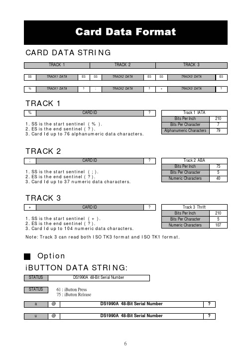
CARD DATA STRINGTRACK 11. SS is the start sentinel ( % ).2. ES is the end sentinel ( ? ).3. Card Id up to 76 alphanumeric data characters.TRACK 21. SS is the start sentinel ( ; ).2. ES is the end sentinel ( ? ).3. Card Id up to 37 numeric data characters.TRACK 31. SS is the start sentinel ( + ).2. ES is the end sentinel ( ? ).3. Card Id up to 104 numeric data characters.Note: Track 3 can read both ISO TK3 format and ISO TK1 format.iBUTTON DATA STRING:OptionSTEP 1 : Run MSR ConfigureSTEP 2 : Choose PS/2 or COM port and press “Scan” ,connect theMSR220/250 reader.START MSRCONFIGURE SOFTWAREApply the bundled disk no. 5296 to begin with the demo software.STEP3 : Click “Read” ,scan the MSR220/250 reader parameter.General :Interface : MSR Interface is being detected. Buzzer : Choose buzzer enable or disable.Feed Back : Set MSR output data ,waiting for feedback from the terminal. Show `Error 'message if no reaction from MSRRS232(UART): Setting MSR communication parameter ,when RS232 and serial USB enable .Package :Setting MSR & iButton data output package .MSR Data Package :iButton Data Package :Data Format :Keyboard : Setting MSR language ,when keybpard enable .FE1 : Package ending character.FS :Package leading character.FE0 : Package ending character.check : Bit check up.iButton: Set iButton data format .Data format :Present ID format : Set present iButton output ID format .Release ID format : Set release iButton output ID format .Family Code : Terms for iButton series.PS : iButton present prompt character.RS : iButton Release prompt character.SS : Start Sentinel ES : End SentinelFF : To set up direct side cardswipe prompt character.RR : To set up reverse side cardswipe prompt character.Swipe Card Direction : To set up prompt character for direct/reverse side card swipe prompt character.Decode Standard : To decode magstripe format.Mark Code :Leading character to set up output data.Decode Mode : To decode magstripe data.Magnetic Card: Set MSR data format and data output parameter .SS : Start Sentinel ES : End SentinelTK ES0 :Ending prompt character .TK ES1 : Ending prompt character .Track Output Order : To set up track data in turn.Track Length : To set up track data length.Head Compatible : To set up the decoding work for IBM or JIS2 data output at one time only.MSR package :JIS2 :JIS2 data format.AAMVA :AAMVA data format .IBM :IBM data format .7Bit : 7 Bits Per Character data.ABA :5 Bits Per Character data .STEP4 : Click “Write” ,write the parameter to MSR220/250 reader .Click “Open or Save” open or save your choose parameter to file. PS.Same as to when MSR220/250 reader is in RS232 interface mode,Keyboard function will be in disable mode .When MSR220/250 reader is in Keyboard function, RS232 interface will be in disable mode.STEP5 : Click “Test Mode” can test the MSR220/250 .STEP6 : Click “Default” can reset MSR220/250 parameter.。
INSTRUCTION BOOK ACRO BE100 用户指南说明书
CONTENTSBefore Using the ProductIncluded ItemsParts NamesPower ManagementConnectionsGetting Started _01Basic OperationsListening to MusicListening to RadioUsing the Device _02Safety Pre-CautionsTroubleshootingCopyrightCertificationsRegistered TrademarksDisclaimersSpecifications Miscellaneous _03020304060911131416181919202021Before Using the Product The descriptions contained in this instruction book are based on the product's default settings.The content of this user guide may differ from that of the actual product depending on the manufacturer's specification changes, and the picture in the user guide may differ from that of the actual product.Some features may not be available depending on the manufacturer or model of the mobile device.Please check with the manufacturer of the mobile device.Failures due to liquid damage are not covered by warranty.Components may change without previous notice toimprove the performance or quality of the product.IncludedItems Quick Start Guide &Warranty CardAdapter plugs (UK, KR, EU, US&JP, CN)FM antenna : Receive FM broadcasts.Power adapter : Supplies power to the product.Adapter plugs : Different plugs for country specific use.Quick Start Guide : A basic guide for using the product.Warranty Card : Please keep the warranty card, since it is required when requesting after-sales service.Product User Guide : The User Guide can be downloaded from the Astell&Kern website:[ Support > Download].Parts Names The appearance of the product as well as the information printed and engraved on the product may vary depending on the manufacturer's specifications.Preset: You can save up to 6 radio channels of your choice.Bass: Adjust the bass level.Play/Pause: Play or pause playback.Power/Volume/Mode:Long press - Turn ON/OFF the product.Short press - Change the mode.Turn the wheel to adjust the sound volume.Treble: Adjust the treble level.Previous Song/Channel: Go to the previous song/ channel.Next Song/Channel: Go to the next song/channel. Power Port: Use this port to connect the power adapter to supply power to the device.Service Port: Use this port for after sales service.AUX IN: Use this port to connect to an external device to output its sound.Antenna Port: Use this port to connect the antenna.Power Manage-ment Connecting the adapter and the plug1. Remove the adapter by pressing the bottom of the cover and lifting it up.2. Select the appropriate plug for your country and slide it down until it clicks in place.3. Change the plug by pressing thebottom and lifting it up.Connecting Power1. Connect the included adapter to the [Power] port on the back of the product.2. Select the appropriate plug for your country, connect it to the adapter, and then connect it to the outlet to supply power to the product.Power adapter specifications: 19V / 3.43ABe sure to use the power adapter that comes with theproduct. Adapters that do not meet the product’s specifica-tions may cause product failure.Moisture on the power port can cause product failure. Besure to completely remove any moisture from the powerport before using it.Make sure to connect the plug that fits the outlet type usedin your country.The adapter may get hot while in use. This is normal anddoes not affect the life or function of the product.Charging the product when the adapter jack is wet candamage the product. Dry it thoroughly before charging.Avoid bending the adapter jack excessively. Doing so maycause the power cable to break.Always unplug the power cable from the outlet beforedisconnecting it from the speaker.Turning the Device On1. Press and hold the [Power/Volume/Mode] wheel to turn on the speaker.The front display will show [BT], and the LED under the [Power/Volume/Mode] wheel will light up.Turning the Device Off1. With the power on, press and hold the [Power/Volume /Mode] wheel.The text will disappear on the front display, and the LED under [Power/Volume/Mode] will also be turned OFF.Front Display Different text will be displayed depending on the mode and context.Bluetooth Mode Radio Mode External Device Connection Radio Channel Saved FM Frequency Treble levels (0/1/2/3/4/5)Bass levels (0/1/2/3/4/5)BTFMAUX99.8 (e.g.,99.8)P 99.8 (e.g.,P 99.8)TREB 0,1,2,3,4,5BASS 0,1,2,3,4,5Connec-tions Connecting to a Mobile Device1. When the product is powered on, it automatically enters Bluetooth Pairing Standby mode.2. Turn ON the Bluetooth feature on your mobile device:[Settings > Connections > Bluetooth]3. Select [ACRO BE100] when it appears in the device search to complete pairing with your mobile device.Entering Bluetooth Pairing ModeUse this mode to connect the speaker with a device other than the currently paired mobile device on Bluetooth.1. Press and hold the [Preset] button for 5 seconds or longer.The front display will show [BT P], and it enters the Pairing Standby state.Basic Opera-tions Button Operations Bluetooth Mode: Press and hold the [Preset] button for 5 seconds orlonger to enter the Pairing mode.Radio Mode: You can save up to 6channels of your choice.Press the [Treble] button to adjustthe treble level.Can be adjusted in 6 levels: 0>1>2>3>4>5Press the [Bass] button to adjust thetreble level.Can be adjusted in 6 levels: 0>1>2>3>4>5Bluetooth Mode: Go to the previoussong.Radio Mode: Go to the previous channel.Play/pause the music or radio.PresetTreble Bass Previous Song/Channel Play/Pause 1 2 34 5Bluetooth Mode: Go to the next song.Radio Mode: Go to the next channel.Long press - Turn ON/OFF the product.Short press - Change the mode.Available in 3 modes: BT > FM > AUXTurn the wheel to adjust the soundvolume.Next Song/Channel Power/Volume/Mode 6 7Connecting an External Device to Listen to Music1. Press the [Power/Volume/Mode] wheel to set it to[AUX] mode.The front display will show [Aux].2. Connect the external device to the [AUX] port on the back with a cable that meets the product’s specifications.3. When you play music on an external device, the music is played through the speaker.Connecting to Bluetooth to Listen to Music1. Press the [Power/Volume/Mode] wheel to set it to [BT] mode.The front display will show [BT].2. After connecting the speaker and the mobile device via Bluetooth, you can play music through the speaker by playing it on the mobile device.3. Use buttons on your mobile device or speaker to use features such as Pause, Play, Next Song, and Previous song.Listening to MusicListening to Radio1. Press the [Power/Volume/Mode] wheel to set it to[FM] mode.The front display will show [FM].2. Press the [ / ] button to go to the desired frequency. The front display will show the new frequency.Pressing the [ / ] button moves the frequency in 0.1 MHz steps.Press and hold the [ / ] button to find and go to an available frequency.3. Pressing the [ ] button pauses/resumes the radio.Saving a Radio ChannelFrequently visited radio frequencies can be saved through the preset feature.1. Go to the desired frequency and press and hold the[Preset] button.2. The current frequency will blink on the front display with P before the frequency, and the channel will be saved.Up to 6 channels can be saved.Listening to RadioListening to a Saved Radio Channel1. In [FM] mode, press the [Preset] button to go to the saved channel.The front display will show the frequency with [P]. 2. Press the [Preset] button to navigate through the saved channels.3. You can use [ / ] to go to a different frequency in the preset mode.Deleting a Saved Radio ChannelIf you have saved all six presets and try to save a different frequency, the front display will show [FULL]. In this case, you must delete a stored preset to save the new channel.1. Go to the frequency you wish to delete and press and hold the [Preset] button.2. The current frequency will blink on the front display, the P before the frequency will disappear, and the channel will be deleted.Safety Precau-tions ProductDo not insert any metal objects (coins, hairpins, etc.) or flammable debris into the device.Do not place heavy objects on the product.If the product gets wet from rain (water), beverages, liquid medicine, cosmetics, sweat, or other moisture, do not turn it ON. Use a soft cloth to wipe the product dry and take it to a service center to be checked. (Failures due to water ingress can be repaired for a fee regardless of the warranty period, however, such damage may not be repairable.)Avoid exposing the device to direct sunlight or extreme temperatures (0℃ - 40℃; 32°F - 104°F) such as the inside of a car during the summer.Do not store or use in hot and humid places such as saunas.Avoid places with excess moisture, dust, or smoke. Do not use for an extended period on blankets, electric blankets, or carpets.Do not place near a fire or in a microwave.Never attempt to disassemble, repair, or alter the product yourself.Do not place the device near magnetic objects (magnets, televisions, monitors, speakers, etc.). Never use harsh chemicals or detergents on the product as doing so can lead to changes in the surface and paint condition.Do not drop the product or expose it to a strong shock (avoid places with strong vibrations. etc.).Do not press multiple buttons simultaneously.Do not press the button too hard.Do not block the vent in the back where the sound comes out.Do not place a fire source such as a candle on theproduct.Do not install or use the product near heat generating devices such as radiators, heaters, or stoves.Do not install the product in an enclosed space, bookcases, or similar places.OtherAvoid using the device during thunderstorms to reduce the possibility of electric shock.Do not listen to music at an excessive volume for an extended period.Trouble-Common issues and solutionsshooting 1. The device won't turn on.Please check whether the power adapter isconnected properly.2. Sound doesn’t come out.Check if the volume is set to [0].Check the volume of the connected mobile device orexternal device.Check the line-out settings in the connected externaldevice.3. The sound is distorted.Check if the volume is too high.Set the treble and bass levels again.4. Cannot connect to Bluetooth.Check the Bluetooth settings in the mobile deviceyou want to connect.Disconnect the mobile device from Bluetooth andtry connecting it again.Move the mobile device close to the product and tryconnecting it again.Move away from devices such as microwave ovensand wireless network-related devices and tryconnecting it again.5. The radio has noise.Adjust the position and height of the antenna.Move the product and check it again.Copyright Dreamus Company retains the rights to patents, trademarks,copyrights, and other intellectual property rights related tothis manual. No contents of this user manual may beduplicated or reproduced in any format or by any meanswithout the prior approval of Dreamus Company.Using or reproducing, in whole or part, the contents of thisdocument is subject to penalties. Software, audio, video,and any other copyrighted contents are protected inaccordance with relevant copyright laws.The user accepts all legal responsibility for the unauthorizedreproduction or distribution of the copyrighted contents fromthis product.Companies, organizations, products, people, and events usedin the examples are fictional. Dreamus Company has nointention to be associated with any company, institution,product, person, or incident through this instruction book,and no such inference should be made. It is the responsibilityof the user to comply with applicable copyright laws.Copyright © Dreamus Company. All Rights Reserved.Certifica- tions KC / FCC / CE / TELECClass B Device (Communication equipment for residential use): This is a Class B Device and is registered for EMC requirements for residential use. This device can be used in residential areas and all other areas.FCC Caution: Any changes or modifications not expresslyapproved by the party responsible for compliance could voidthe user's authority to operate this equipment.This device complies with FCC & IC radiation exposure limitsset forth for an uncontrolled environment. This module maynot be co-located with any other transmitters or antennas.The antenna must be installed such that 20cm is maintainedbetween the antenna and usersRegisteredTrademarksQualcomm aptX is a product of Qualcomm Technologies, Inc.and/or its subsidiaries.Qualcomm is a trademark of Qualcomm Incorporated, registeredin the United States and other countries.aptX is a trademark of Qualcomm Technologies International,Ltd., registered in the United States and other countries.LDAC and LDAC logo are trademarks of Sony Corporation.Disclai- mers The manufacturer, importer, and distributor shall not be liable for damages including accidental and personal injury due to the improper use or operation of this product. The information in this user manual was written based on current product specifications. The manufacturer, Dreamus Company, regularly adds new features via OTA updates and will continue to apply new technologies in the future. Product specifications may be changed without prior notice. There is no warranty against data loss due to the use of this product.Specifi- Arraycations。
海洛斯操作手册(说明书)

HIROSS恒温恒湿机房精密空调操作手册HIMOD系列北京****科技有限公司技术部2009年01月01日目录第一章HIMOD系列海洛斯空调概述 (2)型号多 (3)控制技术先进 (3)制冷系统 (3)送风系统 (3)加湿系统 (3)加热系统 (4)1.7其它 (4)第二章HIMOD系列海洛斯空调型号含义 (4)第三章有关空调的一些资料 (5)气流组织方式(详见下图) (5)盖板纽开启方式(详见下图) (5)空调重量(单位:Kg) (5)机组尺寸及维护空间 (6)第四章制冷循环管路示意图 (7)风冷却(A型) (7)水冷却(W型) (8)双冷源(D型) (9)单系统(C型) (10)双系统(C型) (10)第五章调速风机调速接线示意图 (11)第六章MICROF ACE概述 (12)概述 (12)面板简介液晶显示屏 (13)液晶显示屏介绍 (13)第七章MICROF ACE面板的操作 (13)第八章控制器的使用 (14)控制器(HIROMATIC)概述 (14)控制器的操作 (15)菜单结构 (17)第九章日常维护及特殊维护 (18)日常维护 (18)特殊维护 (19)第十章常见报警及处理 (20)低压报警 (20)高压报警 (21)加湿报警 (21)失风报警 (21)电加热过热报警 (22)显示器发黑 (22)空调不制冷 (22)附录1:参数列表 (22)附录2:报警内容列表 (26)附录3:各菜单项含义: (28)第一章HIMOD系列海洛斯空调概述HIMOD系列海洛斯空调(HIMOD空调)是当今世界上最先进的机房专用恒温恒湿机房专用精密空调。
随着IT业的突飞猛进的发展,各种布局、面积差别很大的机房如雨后春笋般纷纷出现了,使用环境也不一而同。
为适应各种不同要求的机房,新开发的海洛斯HIMOD系列空调应运而生。
她是在保留她的前一代产品HIRANGE系列机房空调的优点,又应用了当今世界上提高了的制冷技术及制冷部件制造工艺,使用当今最先进的模块化设计理念生产出来的高科技机房空调产品。
Argo产品软件操作手册Argox固定资产管理系统

A r g o x产品软件操作手册Argox软件工具操作方法一. 打印机驱动的安装二. ArgoBar Lite操作使用三. Printer Utility操作使用四. Scanner Utility操作使用五. Font Utility操作使用一. 打印机驱动安装(以dr200为例)a.在光盘中把DR200解压缩到硬盘中的某个地方,EG:D:\dr200中;点击开始菜单,选择设置菜单中的打印机;点击添加打印机出现如下对话框:b.在添加打印机向导中点击下一步,选择本地打印机,点击下一步;用户根据自己的情况选择打印端口,如下图:c.出现如下对话框时,点击从磁盘安装d.点击从磁盘安装后,出现如下对话框:点击浏览,(EG D:\dr200),选择 d: \dr200,出现文件夹(为驱动的版本号),点击打开,出现操作系统的选择,用户根据自己的PC机操作系统点击相应文件夹。
e.在点击操作系统的文件夹之后,出现一个 OEMSETUP 文件,选中以后,点击打开后,在从磁盘安装对话框中点击确定按钮,再点击下一步,出现如下对话框:在上图对话框之中,选择英寸非常重要,OS-214、X-1000+/X-2000+和R-400的机型选择4inch,G-6000的机型选择6inch。
f.在完成步骤五之后,点击下一步,用户根据自己的需要选择保留现有驱动程序或者替换现有驱动程序之后,点击下一步,出现如下对话框:g.用户在上图中自由选择是否设置为默认打印机后,点击下一步,出现共享选项,用户自由选择,如下图:h.在g之后,点击下一步,出现打印测试页询问框,建议用户选择是(打印机在打开状态下,并且有并口线或者串口线连接主机)。
在打印完测试页之后出现如下对话框:点击完成即成功装上200的驱动程序。
i.如驱动正确装上,在打印机对话框的添加打印机边上出现如下图的图标,即成功安装了200的驱动程序。
二..ArgoBar Lite操作使用A.页面设置1)进入设置可选择单位英寸或者毫米.2)设置页面大小.可根据实际标签大小设置宽度及高度,弧度及标签的样式(是一行一列或着多行多列)单位不一样输入的数字也将不一样.3)设置边距及间隙可设置标签的左右边距及标签之间的间隙.(注意单位)B.绘制界面在界面的左边有一排图形绘制工具,包括Text,Barcode,Image,Box,Line等等.1)文本设置可在固定资料中输入所需要显示的文本.在左边属性栏中选择字体的各种内容.(在资料来源中可选择计树,时间,导入等方法.)2)1D条码设置所有1D条码包括国际通用的条码,Code39,code93,Ean13,code128等等.3)2D条码设置点开浏览选择已有的文本文档.4)插入图片5)插入直线和黑块.点选相应工具直接在编辑面拉选.C.打印机设置1).进入设置界面2)打印机设置在选项中可选择打印属性,包括碳带,裁刀等.打印温度(PPLB控制在9-12度,PPLA控制在10-13度左右)3)Back feed offset(倒退位移)a.使用COMMAND的倒退位移选择PRINTER COMMAND选择PPLA语言点击打印机设置这里可以选择倒退位移可以设置倒退位移的长度选择PRINTER COMMAND选择PPLB语言点击打印机设置这里可以选择倒退位移但是不能设置倒退位移的距离b.使用DRIVER的倒退位移选择列表中的Tear off Enabled 如果没有这个选项, 请登陆下载最新的驱动程序如果是WINDOWS98 选择打印机属性点击箭头所指的按钮设置完成后,点选打印动作三.Pinter Utility 操作使用PS:针对小标签纸的精确设置,先把打印机连上电脑,开机 A.使用选择列表中的Tear off Enabled 如果没有这个选项, 请登陆下载最新的驱动程序如果是WINDOWS2000 选择打印机设置点击高级按钮1).选择打印机类型2)选择打印机语言3).选择通信端口选择机器语言 Os 系列默认为PPLA X 系列默认为PPLB选择打印机类型4).选择单位5).设置标签高度选择单位建议选择millimeter 注意:实际单位为:0.1m选择通信端口 一般为并口6)设置标签间隙高度7)设置纸张感测头等级勾上第二项在此处填上 间隙高度 (注意单位)勾上第一项在此空白处填上 标签高度(注意单位)8)传送设置B.F/W Dowland1).参数选择选择步骤5,6,7中的一个或多个后,点击send 键,确定后重启打印机即可勾第十三项选择感测头等级 Level 4或level 52)选择源文件3)更新firmware1.选择我公司 提供的文件2.点击打开3.选择通信端口1.选择机器型号2.选择机器语言点击此处, 选择firmware 源文件四.Scanner Utility 操作使用PS:用串口线把扫描枪接在pc 机的串口上进行更新 1)把源文件拷到相应目录下2)设置串口参数我公司提供的三个源文件安装Scan utility 目录下 的ROM 文件夹1.点击此处 弹出对话框2.点击确定, 会有进度条出现, 等待进度条完成, 确定后重启打印机 即更新完毕3)设置串口参数2.选择通信端口1.打开scan utility, 点击此处4) 更新firmware1.点击此处3.填上如图的参数五.Font Utility 的操作使用 1.菜单说明: Convert Font File 编辑字体文件 Download Font File 下载字体文件Text PPLA Soft-Font 测试下载PPLA 的软字体 Text PPLB Soft-Font 测试下载PPLB 的软字体 Communication Port 选择端口 Printer Type 打印机选择 Printer Language 打印机语言选择 Delete Printer Font 删除打印机软字体 Memory Available 选择存储设备 2.使用说明: 步骤一设置打印机端口,选择打印机,打印机语言.点击确定,会出现 进度条,等待数分钟 后扫描枪会“嘀”一声 然后进度条消失。
第三届大赛-六轴-C30 操作手册V1.0_ePad

版本号:ePad_V1.0EFORT机器人C30系统操作手册目录第一章安全 (1)1.1安全责任 (1)1.2安全预防措施 (1)1.2.1目的 (1)1.2.2定义 (1)1.2.3适用范围 (2)第二章欢迎使用埃夫特机器人 (6)2.1示教器 (6)2.1.1关于示教器 (6)2.1.2功能区与接口 (7)2.1.3如何握持示教器 (9)2.2启动系统 (9)2.2.1本体检查 (9)2.2.2系统连接 (10)2.2.3系统上电 (10)第三章操作界面 (11)3.1界面布局 (11)3.1.1状态栏 (11)3.1.2任务栏 (12)3.1.3桌面 (12)3.2登录 (13)3.3桌面上的设置APP (14)3.3.1语言设置 (14)3.3.2IP设置 (15)3.3.3机器人型号设置 (16)3.3.4服务 (18)3.3.5轴参数 (20)3.3.6DH参数 (22)3.3.7切换Logo (23)第四章点动操作 (26)4.1什么是点动操作 (26)4.2坐标系统介绍 (26)4.2.1工业机器人-关节坐标系 (26)4.2.2工业机器人-笛卡尔坐标系 (26)4.2.3工业机器人-工具坐标系 (27)4.2.4工业机器人-用户坐标系 (27)4.3点动操作注意事项 (27)4.4开始点动操作 (27)4.4.1关节坐标系-点动操作 (28)4.4.2笛卡尔坐标系-点动操作 (29)4.4.3工具坐标系-点动操作 (29)4.4.4用户坐标系-点动操作 (30)4.4.5点动-快速运动 (30)4.4.6点动-慢速运动 (31)4.4.7点动-步进运动 (32)第五章坐标系管理 (33)5.1工具坐标系标定 (33)5.1.1工具标定 (33)5.1.2修改工具 (37)5.2用户坐标系标定 (38)5.2.1用户坐标系标定 (38)5.2.2修改用户坐标系 (40)第六章零点恢复 (42)6.1零点恢复简介 (42)6.2零点恢复操作步骤 (42)6.3零点文件重写 (43)第七章文件管理与编程 (44)7.1文件管理 (44)7.2编辑程序 (45)7.2.1程序变量的操作 (46)7.2.2程序指令的操作 (48)7.3调试程序 (51)7.4子程序 (56)第八章故障处理 (59)8.1控制器故障处理 (59)8.1.1查看事件日志 (60)8.1.2控制器的故障处理 (61)8.2驱动器故障处理 (62)8.3程序运行故障处理 (62)附录1 (63)附录2 (80)第一章安全1.1安全责任✓系统集成商负责确保机器人和控制系统按照安装所在地国家施行的《安全规范》安装使用。
- 1、下载文档前请自行甄别文档内容的完整性,平台不提供额外的编辑、内容补充、找答案等附加服务。
- 2、"仅部分预览"的文档,不可在线预览部分如存在完整性等问题,可反馈申请退款(可完整预览的文档不适用该条件!)。
- 3、如文档侵犯您的权益,请联系客服反馈,我们会尽快为您处理(人工客服工作时间:9:00-18:30)。
ARGOS 操作手册
(操作者用)
Mania Pacific Limited
2003年8月
第一章进入、退出Argos系统
1、开机
1、打开机台电源。
启动电脑。
2、登陆用户名和密码分别是:
user:aoi
passward: barco1
3、启动完成后双击桌面Argos图标,随即进入Argos系统。
等待系统初始化。
4、此时注意有无异常声响。
2、关机
1、退出Argos,在主界面状态下
单击Tools按钮(图一)——单击Exit Argos(图二)
图一
图二
第二章Argos的基本操作1、读取资料
首先读取比较需要的资料
单击Jobs按钮(图三)――选择需要的料号名称(图四)
Argos将自动读取资料并将资料显示
图三
图四
新资料
1、在第一次读入时,将出现一个对话框(如图五),提示创建新参数,击 YES;
3、通常选择与检测板基材名称相同的基材参数(见图六)。
完成后单击OK键。
图六
2、设定检测参数
1、检测参数
图七显示的是一个检测料号的基本参数,从上到下分成四个区域。
1、区域一:
区域一中的参数主要是描述线路板的。
参数英文名称参数中文名称设定方法建议设定值Maximum Defects Per
Panel
每块最大缺点数100~150
Minimum Defect Size
Reported 最小报告缺点的大小
安质量部门的要求
值设定
通常不要小
于1
Maximum Ink Marks Per
Panel
每块板最多Ink Marks 的点数 100
Auto Review Defects
Delay 进行缺点确认等待的时间 1
s
Panel Thickess 板厚用千分尺测量
Defect Review Motion 错误显示等待的时间 1
s
Delay
图七
2、区域二:
参数英文名称参数中文名称设定方法建议设定值
Material Name 材料名称(检测材料的种
类)
选择与要检测材料
相同参数
Polarity 极性保持图形与线路板
图形相同
3、区域三
参数英文名称参数中文名称设定方法建议设定值
Flip Panel Inspection 双面检测选择相同线路板的另一面文件
4、区域四
为方便扫描检测而设定的一些选项
参数英文名称参数中文名称作用建议
Pinned Panel 定位钉让Argos记下板子的位置,不用对位
Skip Rubbersheeting 不选此功能
Skip Thresholding 略过临界值让Argos不进行临
界值确认
不选此功能
Enhanced Deection
Mode
增强模式不选此功能
Mirror Reference File 镜像参考文件对参考资料进行镜
像
根据情况选
择
View Reference File 显示参考文件
Auto Review Defect
After Inspection
检测后自动浏览缺点选用此功能
Auto Inkmark 自动墨水标注根据情况选
择
2、CAD参数(图八)
CAD参数的更改将改变参考资料的图形,所以改动时请小心,不要随意改动。
参数英文名称参数中文名称作用建议设定值
Outer Tolerance 正公差设定线路边缘突出的
最大容许
客户自定
Inner Tolerance 负公差设定线路边缘缺少的
最大容许
客户自定
Don’t care Tolerance 不检测区范围远离线路设定值的以
外的区域不检测
客户自定
Universal tolerance 通常的公差
Etch Factor 蚀刻因子将线路安设定值缩小参考工艺文件
Corner Round 尖角圆弧将尖角的地方用圆弧
代替
参考工艺文件
通常是1~2
对CAD参数操作后,Argos将重新处理软件。
需要等待一定时间。
图八
3、检测参数的调整
参数名称通常设定值调整与侦测能力Minimum Defect
Size Reported
2~4 数字增大侦测能力降低错误点减少Outer Tolerance 2 数字增大侦测能力降低错误点减少Inner Tolerance 2 数字增大侦测能力降低错误点减少Don’t care
Tolerance
20~40或更大数字增大侦测范围提高误点增加
Etch Factor 1或根据工艺文件改变资料线路的大小,与侦测能力无关。
设大或小都会有错误点出现
Corner Round 1或更大改变资料转角处蚀刻造成的圆角与侦测
能力无关。
设大或小都会有错误点出现
第三章问题点的处理
1、减少缺点报告
减少缺点报告的数量可以分三步
一、使用清洁滚轮,清理板面的灰尘、杂物等等。
对于干膜板可以清除大
部分干膜屑。
二、调整临界值的大小,使红色与绿色各占50%左右。
也可以通过错误
列表中的显示作为调整的依据。
三、更改一些公差参数,如何更改参考第二章-第三节中的表格
2、增加侦测能力
增加侦测能力的方法从三方面实现
1、确认临界值是合适的。
2、按照第二章-第三节中的表格提高侦测能力。
3、在调整临界值时,适当加大DSP的数值。
第四章其他
1、板厚设定不正确或线路板有翘弯会出现的报错
解决方法:检查板厚、检查真空吸气
2、对位点不正确
解决方法:重新设定对位点
3、临界值设定不当
调整临界值,直至另一面的图形消失。