MLX 系列减速机操作手册英文版
Steridose Sterimixer和Sanimixer操作手册说明书

版权所有 © 2018 Steridose由 Steridocs 创建:2018 年 03 月 08 日 安装与操作 | 1ZHSterimixer 和 SanimixerSTD0016CN00适用于:Steridose 产品 Sterimixer ®-Low-Shear SMO/SMA 、Sterimixer ®-Medium-Shear SMMS 、Sterimixer ®-ATEX 、Sanimixer 。
目录1 重要安全信息 2 1.1 简介 ................................................................ 2 1.2 安全术语和符号 ............................................ 2 1.3 通用安全 ........................................................ 2 1.4 用户安全 .. (2)2 处理3 安装和试机3 3.1 安装轴承单元 ................................................ 3 3.2 安装叶轮 ........................................................ 4 3.3 使用轴承/叶轮安装工具(选项) ............... 5 3.4 安装和拆卸驱动单元 .................................... 5 3.5 连接电源 ........................................................ 6 3.6 安装检查和校准 .. (6)4 操作7 4.1 允许的工作温度范围 .................................... 7 4.2 允许的压力范围 ............................................ 7 4.3 化学相容性 .................................................... 7 4.4 操作限值 ........................................................ 7 4.5 进一步的操作建议 ........................................ 9 4.6 Sterimixer/Sanimixer 消毒指南 ...................................... 10 4.7 在 ATEX 应用中使用 Sterimixer/Sanimixer 的特定信息 ..................................115 维护12 5.1 试机/磨合期间的日常维护 (13)6 故障排除 13安装与操作手册2|© Steridose1. 重要安全信息1.1. 简介1.1.1. 本手册的用途安装和使用产品前请仔细阅读本手册。
SEW MOVITRAC B 操作面板 说明书

操作面板操作手册 — MOVITRAC® B
3
1
重要提示 安全提示的组成
5
2
安全说明 运输和仓储
2.4 运输和仓储
请遵守有关运输、仓储和正确处理设备的规定。请遵守 “一般技术参数”一章中有关温 度条件的规定。
2.5 安装
设备的安装和冷却必须按照相应文件中的规定进行。
注意保护变频器。特别是在运输和接触变频器时,决不可弯折元件和 / 或改变隔离间距。 注意避免接触电气元件和触点。
5 服务 ................................................................................................................... 28 5.1 故障存储器 .............................................................................................. 28 5.2 操作面板复位 .......................................................................................... 28
符合基本安全说明定义的电气专业人员必须知晓产品安放、装配、开机调试和运行等操 作,同时具备相应的操作资格。
其他操作如运输、仓储、运行和废弃处理等必须由受过相应培训的人员进行。
FOSS官方资料 FT120中文操作手册
MilkoScan FT-120乳品分析仪中文操作手册北京福斯杰科技有限公司F os s C hi na Se r vi c e Ce n te r2000年6月目录第1章简介 (5)§1。
1FT—120乳品分析仪 (5)§1。
2关于这本手册 (6)§1。
3福斯电子的校准模块 (6)§1。
4FT—120仪器可选择的模块 (7)§1。
4。
1自动清洗和调零模块(ACZ) (7)§1。
4。
2 应用模块 (7)§1。
4。
3 天平选项 (7)§1。
4。
4 高级性能模块 (7)§1。
4。
5高级校准模块 (8)§1。
4。
6 输入选择模块 (8)§1。
4。
7 数据交换选择模块(DDE) (8)§1。
4。
8 品质确认模块 (8)§1。
5窗口系统 (9)§1。
5。
1 菜单栏 (9)§1。
5。
2 功能键 (10)§1。
5。
3 按钮栏 (10)§1。
5。
4 滚动栏 (10)§1。
5。
5 状态栏 (10)§1。
6定义自己的窗口 (10)§1。
7仪器语言支持 (10)§1。
7。
1 怎样使用当地语言 (11)§1。
8激光的保险装置 (11)第2章FT—120乳品分析仪用户界面 (11)§2。
1FT—120乳品分析仪插图屏幕说明 (12)§2。
2按钮板 (13)§2。
3功能键 (13)§2。
4快捷键 (14)§2。
5其它菜单 (14)§2。
6菜单概要 (15)§2。
6。
1 菜单中的基本模块 (15)§2。
6。
2 应用模块菜单 (16)§2。
7物理连接与转换 (16)第3章操作 (18)§3。
1调零和实验样品 (18)§3。
SEW减速机润滑系统操作手册

03/2004操作维护手册目录带水冷却器的压力润滑带空气冷却的压力润滑不带冷却器的压力润滑 压力润滑部件轴端泵SHP 过滤器可视污染指示器电子污染指示器水冷却器板水冷却器管空气冷却器温控水阀温控开关压力开关压力安全阀电子流量监视器压力润滑系统说明书编号 名称U210U211U212U213106026400264101641026200362005620026400664109641106400564106页码3.1.13.1.23.1.33.1.43.2.13.3.13.3.23.3.33.4.13.4.23.4.33.4.43.4.53.5.13.5.23.5.3安全说明1、制造商的承诺和买方的责任买方和SEW 公司共同对SEW 减速机的选型负责。
买方提供以下参数:驱动类型,运行工作制和运行条件。
最终的选型由SEW 完成。
SEW 对所选型负责。
为了确保保证的有效性,买方必须保证减速机的存放、安装、润滑、运行和保养严格按照SEW 的说明和合同中表明的运行条件执行。
运输、安装、运行保养和检查应当由专业的技术人员来完成;否则容易损坏减速机。
由于总承包商掌握减速机影响因素,所以他应对驱动系统的稳定性负责。
连接旋转部件的系统应当是相互协调的、在临界速度下运转自如的,扭矩和在特定的速度范围内其它类型的振动也应如此。
特殊环境和容易损坏机器的操作必须通知SEW 。
质保期仅仅针对按照SEW 的说明执行的用户。
2、安全2.1 温度运行时减速机的外表面温度超过60℃。
对于飞溅润滑和浸式润滑的减速机,表面温度可达到100℃。
2.2 噪音根据减速机的额定机械功率和类型,噪音值会不同。
噪音的测量方法按照DIN45 635或ISO 8579执行。
要了解减速机的噪音值请联系SEW 。
2.3 旋转部件的保护为了确保旋转部件不被接触,适当的防护罩必须提供,这一点也是安全法所要求的。
当减速机在运行时,机械的防护罩必须不能移动。
诺德减速机操作手册
_1_减速机操作手册B 1010_1040_CN 重要提示..............................................2 适用范围..............................................3 安全须知..............................................41 减速机型号及附件......................................5 1.1 NORD 减速电机型号举例说明.........................5 1.2 减速电机的铭牌....................................62 设备的运输及储存......................................7 2.1收货及检验 ........................................7 2.2设备的搬运 . (7)2.3设备的储存 (8)3 设备的安装............................................9 3.1安装前的准备和检验 .. (9)3.2减速电机的安装 (10)3.3 减速机空心轴的安装...............................12 3.4 扭矩臂的安装.....................................13 3.5空心轴锁紧盘的安装 . (14)3.6 IEC 标准电机的连接................................16 3.7逆止器的连接 . (17)3.8电机的连接 (18)4 电气接线.............................................195 设备的运行...........................................23 5.1 检查油位.........................................23 5.2 激活IEC 适配器自动补油杯.........................24 5.3 减速机效率.......................................25 5.4 检查减速电机.....................................25 5.5 自检项目清单.....................................266 减速机的维修与保养...................................27 6.1 维修与保养.......................................27 6.2 减速电机的全面维修保养...........................29 6.3 润滑油的注油量...................................30 6.4 润滑油的品牌表...................................377 常见故障现象及分析...................................38附件一、安装位置表..................................... 39附件二、零件清单........................................45附件三、螺栓力矩........................................58附表一 减速机各形式及附件的代号与含义...................59附表二 电机各形式及附件的代号与含义.....................60 _2_减速机操作手册B 1010_1040_CN重要提示① 本操作和维护手册(以下简称手册)是减速电机供货不可缺少的组成部分。
流体动力公司限动器B320系列斜齿轮操作员手册说明书

Limitorque B320 SeriesBevel Gear OperatorsRugged and dependable for manualor motorized valve control applicationsExperience In Motion2B320 bevel gear operators provide mechanical advantagefor multi-turn actuation applicationsThe Flowserve Limitorque B320 bevel gear operator notonly makes it easy to manually operate multi-turn valves— it also makes it easy to convert to motorized service.Limitorque offers the B320 in an extended array of standardsizes and configurations to cover the widest range of appli-cations, with the most common units are in stock forimmediate shipment. Limitorque also accommodatesspecialized needs with a variety of options, includinghandwheels, chainwheels, spur gears, and operating wrenchnuts. Like every Limitorque product, the B320 is backed byFlowserve’s worldwide service and parts supply network.3The B320 offers torque ranges up to 8,000 ft-lb (10,856 N m) and thrust capacities to 325,000 lb (1445 kN), for any application demanding a bevel gear operator with superiorstrength and accuracy. It is most commonly used with sluice/slide gates, gate valves, and globe valves.B320 features: built for reliable valve control — whether manual or motorizedAvailable options for the B320 operator include:Flowserve Limitorque has designed the B320 to be configured to each customer’s needs. Choose an optional handwheel for manual actuation. Add a spur gear attachment for greater mechanical advantage. And when manual operation simplyisn’t practical, just couple the B320 with one of Limitorque’s electric actuators for an economical, motorized, multi-turn package.Easily adaptable for other applicationsDirect mounting to an electric valve actuatorSolid construction inside and outAll B320 series operators are manufactured from the highestquality materials for maximum reliability. All gears are machinedfrom high-strength alloy steel, ensuring smooth operation withminimum backlash. Input and output bevel gears — as well asthe bevel pinion itself — are supported on low-friction rollerbearings. Every B320 operator is permanently lubricated and fullywaterproof to endure the harshest outdoor service. B320 seriesoperators are suitable for weatherproof (NEMA 4) or temporarysubmergence service (NEMA 6, IP 67/68). All units are easilyconverted for motorized applications.Bevel pinion and bevel gears are completelysupported on anti-friction ball bearings.45Rugged cast iron enclosure meets the most severe environmental conditions.Machine-generated gearing assuresminimum backlash and smooth operation.Splined bronze alloy stem nut is removablefor threading or custom bore and key.6Physical Dimensions for B320 Series Bevel Gear Operator with MSS and ISO Mounting Base1BM Mounting baseC Mounting holesstraddle centerlineF DiameterV Length of nutB320-20 through -80 Operators B320-90 operatorsB320 Series-20 through -90 bevel gear operator dimensionsNote 1: Two-piece drive sleeve standard. Optional one-piece drive sleeve available.Note: • Dimensions for “P” are always shown in inches.• Dimensions for “N” are always shown in millimeters.• DP = deep; BC= bolt circle7Physical Dimensions for B320 Series Bevel Gear Operator with 3:1 Spur Gear Attachment and MSS and ISO Mounting BasesC Mounting holes straddle centerline M Mounting base diameter F DiameterH 1.6B320-20 and -40 Series bevel gear operator with spur gear attachment dimensionsNote: • Dimensions for “P” are always shown in inches.• DP = deep; BC= bolt circlePhysical Dimensions for B320 Series Bevel Gear Operator with Spur Gear Attachment and MSS and ISO Mounting Bases.20 Pilot depth(5)C Mounting holes straddle centerlineN Metric keywayD Pilot diameter M Mounitng base diameterF DiameterE Diameter4.7(119)A Maximum stem threadedJB320-50 through -80 series bevel gear operator with spur gear attachment dimensions• Dimensions for “N” are always shown in millimeters.• DP = deep; BC = bolt circle8B320-90 series bevel gear operator with spur gear attachment dimensions• DP = deep* BC = bolt circle9General SpecificationsInput torque can be calculated by dividing required output torque by ratio by efficiency.Example: B320-20 at full manual ratingInput torque: 750 / (3 x 0.90) = 277 ft-lb1017 / (3 x 0.90) = 376 N mNote 1: Two-piece drive sleeve standard. Optional one-piece drive sleeve available.10 This page is left intentionally blank.11Flowserve CorporationFlow ControlUnited StatesFlowserve Limitorque5114 Woodall Road,P.O. Box 11318Lynchburg, VA 24506-1318Phone: 434-528-4400Facsimile: 434-845-9736EnglandFlowserve LimitorqueEuro HouseAbex RoadNewburyBerkshire, RG14 5EYUnited KingdomPhone: 44-1-635-46999Facsimile: 44-1-635-36034JapanLimitorque – Nippon Gear Co., Ltd.Asahi-Seimei Bldg. 4th Floor1-11-11 Kita-Saiwai, Nishi-KuYokohama-Shi, (220-0004)JapanPhone: 81-45-326-2065Facsimile: 81-45-320-5962CanadaFlowserve Limitorque120 Vinyl CourtWoodbridge, Ontario L4L 4A3CanadaPhone 905-856-4565Fax 905-856-7905SingaporeLimitorque Asia, Pte., Ltd.12, Tuas Avenue 20Singapore 638824Phone: 65-6868-4628Facsimile: 65-6862-4940IndiaFlowserve Limitorque423 Jaina Towers IIDistrict Centre, JanakpuriNew Delhi, India 110058Phone: 91-11-2561-4486ChinaLimitorque Beijing PTE LTDRM A1/A222/F, East Area, Hanwei PlazaNo. 7 Guanghua RoadFlowserve Corporation has established industry leadership in the design and manufacture of its products. When properly selected, this Flowserve product is designed to perform itsintended function safely during its useful life. However, the purchaser or user of Flowserve products should be aware that Flowserve products might be used in numerous applicationsunder a wide variety of industrial service conditions. Although Flowserve can (and often does) provide general guidelines, it cannot provide specific data and warnings for all possibleapplications. The purchaser/user must therefore assume the ultimate responsibility for the proper sizing and selection, installation, operation, and maintenance of Flowserve products.The purchaser/user should read and understand the Installation Operation Maintenance (IOM) instructions included with the product, and train its employees and contractors in the safeuse of Flowserve products in connection with the specific application.While the information and specifications contained in this literature are believed to be accurate, they are supplied for informative purposes only and should not be considered certified oras a guarantee of satisfactory results by reliance thereon. Nothing contained herein is to be construed as a warranty or guarantee, express or implied, regarding any matter with respectto this product. Because Flowserve is continually improving and upgrading its product design, the specifications, dimensions and information contained herein are subject to changewithout notice. Should any question arise concerning these provisions, the purchaser/user should contact Flowserve Corporation at any one of its worldwide operations or offices.© 2009 Flowserve Corporation, Irving, Texas, USA. Flowserve is a registered trademark of Flowserve Corporation.。
MLX200立磨减速机使用说明书

1.概述MLX200立式水泥磨减速齿轮箱采用圆锥齿轮与行星齿轮联合传动形式,一对直角传动的圆锥齿轮与一套输入轴为垂直向上的行星传动,通过双齿联轴器将二者联接起来。
太阳轮用球头支承在推力盘上,立式磨机的轴向支承由一个扇形的油模可倾瓦推力轴承来承受,这两个自由度使内圈及三个行星轮受力均匀。
内齿圈被刚性的固定在箱体上,设计成圆筒状箱体为轴向推力轴承提供了理想的支撑形式。
另外,圆筒状箱体的内外壁都配置了对称的加强筋,是箱体有很好的刚性。
输出轴与行星架焊成一体使结构简单合理。
圆锥齿轮采用克林根贝尔齿形的螺旋齿,太阳轮,行星轮为渐开线直齿,这些齿轮均采用高强度的渗碳钢,齿轮经渗碳磨齿具有较高的精度。
减速齿轮箱的所有支承轴承均采用滚动轴承,轴向推力轴承为可倾瓦推力轴承,由十六块扇形轴瓦组成,它承受立式磨机的轴向推力。
工作时轴瓦直接浸泡在油池中,并经过环形喷嘴不断提供新鲜润滑油,使油池始终保持一定的液面高度,当滑油系统突然停止工作或发生其它机械故障时,使磨机仍然能工作一段时间。
滑油系统采用独立的油站,并有油压,油温的自动保护系统,使全套装置工作时安全可靠。
2. 主齿轮箱技术性能参数:齿轮箱连续功率:N=1950KW 输入转速:n1=994r/min额定垂直静载荷:F静=5100KN 垂直动负荷:F动=16600KN减速比:I=41.058 齿轮箱重量(千克):G=51183.6齿轮箱用润滑油:硫磷型极压工业齿轮油N320齿轮箱用油入口温度:37~43°C3 减速齿轮箱的安装与找正:3.1地基:减速齿轮箱必须安装在刚性好,无振动,水平的地基上,例减速齿轮箱可安装在支承面经过机械加工的基础框架上,基础框架须与水泥基础浇灌成一体。
经找正后的齿轮箱心须用锥销定位后再用螺栓把其也基础框架连接在一起。
3.2找正:3.2.1减速齿轮箱与主电机找正齿轮箱与主电机相连接的输入轴在运转必须与电机轴同心。
为了满足这个需要,其轴向与经向跳动必须用专用测量装置来测量,具如需要R>200mm,轴向跳动值可相应增大3.2.2减速齿轮箱与磨机的安装与找正:减速齿轮箱与磨机之间的安装工作必须正确而细致的进行。
MFY中心传动磨机减速器 使用说明书
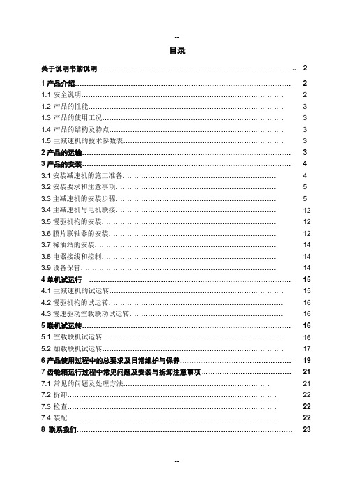
目录关于说明书的说明 (2)1产品介绍 (2)1.1 安全说明 (2)1.2 产品的性能 (3)1.3 产品的使用工况 (3)1.4 产品的结构及特点 (3)1.5 主减速机的技术参数表 (3)2产品的运输 (3)3产品的安装 (4)3.1安装减速机的施工准备 (4)3.2安装要求和注意事项 (5)3.3主减速机的安装步骤 (5)3.4主减速机与电机联接 (12)3.5慢驱机构的安装 (12)3.6膜片联轴器的安装 (12)3.7稀油站的安装 (14)3.8电器接线和控制 (14)3.9设备保管 (14)4单机试运行 (15)4.1 主减速机的试运转 (15)4.2慢驱机构的试运转 (16)4.3慢速驱动空载联动试运转 (16)5联机试运转 (16)5.1 空载联机试运转 (16)5.2 加载联机试运转 (17)6产品使用过程中的总要求及日常维护与保养 (19)7齿轮箱运行过程中常见问题及安装与拆卸注意事项 (21)7.1 常见的问题及处理方法 (21)7.2 拆卸 (22)7.3 检查 (22)7.4 装配 (22)8 联系我们 (23)关于说明书的说明:产品的采购方或经销商应确保本说明书或其内容传递到最终用户。
为确保本减速机发挥最大的功能作用,请用户使用前仔细阅读本说明书,以保证MFY 系列减速机安全正确的安装、使用和维护。
只有在符合本说明书的情况下,保修期才有效。
本说明书是所提供的减速机的组成部分之一,不可随意存放甚至丢失,应妥善保管,以便随时参考。
为保证技术进步,我们保留对个别零部件进行变更的权力,这些变更是为了提高减速机的效率和安全性以及其他特殊属性。
如有疑问请联系我们,以获得帮助。
1产品介绍1.1 安全说明,以下情形会产生严重人身伤害与设备损坏:1.1.1 温度、噪音减速机运行时外表面温度可能达到60℃-90℃,要注意由此引起的安全隐患。
如减速机出现异常现象(如表面过热,异常噪音等)应立即停机。
- 1、下载文档前请自行甄别文档内容的完整性,平台不提供额外的编辑、内容补充、找答案等附加服务。
- 2、"仅部分预览"的文档,不可在线预览部分如存在完整性等问题,可反馈申请退款(可完整预览的文档不适用该条件!)。
- 3、如文档侵犯您的权益,请联系客服反馈,我们会尽快为您处理(人工客服工作时间:9:00-18:30)。
MLX Series Gear Box of Cement MillOperating Manual·Transmission device and gear box shall be operated by the personal who is familiar with the operating.Please read the manual carefully before operating.·This gear box has been drained out of oil when delivered from the workshop, therefore,please fuel the oil according to the operating manual.·Please hand over this operating manual to the actual operating personal·Be sure to keep this operating manual in good way.Safety Caution●Before using(installation,operation,maintenance,spot check,etc.),must befamiliar with this operating manual and other subsidiary information and operate correctly.Being familiar with the machine knowledge,safety considerations and matters should be paid attention to and then use it.After reading,it should be in actual use personnel's custody and kept in visible place.●While carrying,setting up,routing the pipes,the machine running,operation,maintenance and inspection,it must be implemented by the personnel with professional knowledge and skills.Otherwise,it may result in injury or damagethe machine.●Set safety protection facilities beside manned unit,to avoid unit’s rapid movingcause human injury and unit damaged●When using the lifting unit,set safety facilities beside it to avoid lifting bodyfalling and cause human injury and unit damaged●During equipments'running,please do not dismantle reducer.In addition,even ifthe equipments stop,the input,output flange of gear unit in connection status with the motor and the other machine,please do not dismantle anything except the checking oil port,oil discharge port,checking cover portion,because it may result in gear meshing offsetting,falling and flying away quickly and other personal injury or damage to the unit.●Do not use it outside the range of the reducer's specifications.It may lead topersonal injury and device damage.●Do not put fingers and objects into the opening of the reducer,which may causeinjury and device damage.●Do not use the damaged reducer,which may cause injury and device damage.●The product transformation by customer privately is outside the scope of thecompany's quality assurance,which our company is not responsible for.●Do not remove the nameplate.●Please refer to the instructions of the oil station for the usage of gearbox oftakeout oil station and oil station.ContentsⅠ.OverviewⅡ.Performance Parameter1.Operational Environment2.Product SpecificationsⅢ.Receiving Inspection1.Precautions2.Inspection RequirementsⅣ.Lifting、Carriage and Preservation1.Lifting2.Carriage3.PreservationⅤ.Installation and Alignment1.Precautions of Installation2.Foundation3.AlignmentⅥ.Records of Field installation,Adjustment and Test RunⅦ.Operation and Maintenance of Reduction Gearbox1.Start2.Shut-down3.MaintenanceⅧ.Regular CheckingⅨ.Precautions of Dismounting and Assembling of Reduction Gearbox 1.Dismounting2.Checking3.AssemblingⅠ.OverviewThe speed reducer gearbox for MLX(1)50series vertical grinding mills adopts the joint transmission with cone gear pair,gear pair with parallel axes and planetary gear pair.A pair of orthogonal transmission cone gear pair,a gear pair with parallel axes and a set of input shaft for vertical planetary gear transmission;they are connected by pairs of gear coupling.The sun wheel is supported on the thrust block. The vertical mill’s axial bearing is supported by12fan-shaped tilting tile thrust bearing.The two degrees of freedom make internal gear ring and three planetary wheels bear force evenly.The inner gear ring is rigidly fixed on the box body,which, designed into cylinder housing shape,provides an ideal support form for the axial thrust bearing.Besides,the inside and outside walls of cylinder casing are configured with symmetrical reinforcement,thus the body has very good rigidity.The0utput shaft and planet carrier become integrated,making the instructor simple and reasonable.The cone gear adopts Klingelnberg style spiral gear.The parallel shaft gear pair, the sun wheel,and the planet wheel are involute straight tooth.These gears adopt high strength carburized steel,witch,after carburized gear-grinding,are of high precision.All the supporting bearings of the speed reducer gearbox are rolling bearings. The axial thrust bearings are tilting tile thrust bearings.Consisting of several piece of fan bearing shell,they bear the axial thrust of vertical grinding mill.During operation, the bearing bushing is always soaked in the oil tank and constantly offered with fresh lubrication oil through the ring nozzle.So the oil tank always maintains a certain level.Lubricating oil system uses independent stations.And there is oil pressure,oil temperature automatic protection system,making the operation of the whole equipment safe and reliable.Ⅱ.Performance Parameter1.Operational EnvironmentAmbient temperature:-20℃~+40℃Ambient humidity:Below85%Air environment:there should be no corrosive gas,explosive gas and steam,etc.there should be no dust either,and the ventilation should be good.-If the installation is in an environment violating the above requirements,it belongs to special order.Please contact with us.-When making the order,if it is pointed out that the equipment will be installed outdoor and explosion-proof,and everything follows the requirements,the installation under certain circumstance is without problem.-The operation should be in a place where the inspection and maintenance,etc.are easy to do.-It should be installed on the platform with good rigidity.2.Product Specifications(For the detail,please refer to the drawing)Ⅲ.Receiving Inspection1.PrecautionsOpen the box after you check the above and below.Do not let it hurt others.Check whether the goods you received is the same as you ordered.If you installed the wrong product,this might bring damage to people or the machine.Do not remove the nameplate.2.Inspection requirementsAs for the driving device and the reducer,you should check the following items.If there are any problems,please contact our representatives,our own store or office which is nearest to you.(1)Whether what is written on the nameplate is the same as what you ordered.(2)Whether there is any damage in transit.(3)Whether the bolts and nuts becomes flexible.Ⅳ.Lifting、Carriage and Preservation1.Lifting·Please do not stand under the goods to prevent from the safe accident when lifting.·Please pay attention to the lifting position and lift as shown in the illustration lightly.·Pay attention to the risk of falling and reversion when e lifting bolts and lifting hole to lift the actuating unit or gear box.But after they are installed in the equipment,so not use lifting bolts or lifting hole to lift the whole equipment.Because falling,inversion or lifting bolts and holes’damage will lead injury or equipment damaged.·Weight of the driving device and the reducer shall be confirmed according to the nameplate,case,outside view and the sample before lifting.And if it is beyond the rated weight,the lifting shall be not allowed to prevent from the accident.Notice:Lifting directly by the output flange is definitely not allowed2.Carriage·Lubricating oil in the gears box shallbe eliminated before the carriage.·Gears box shall be fixed reliably.·Measures to protect from wind,rainand moisture shall be taken.·Place it directly on the ground is notallowed3.PreservationWhen the driving device or the reducer doesn’t work immediately,they shall bekept according to the matters detailed as below.1)Preservation place·The place shall be clean and dry.The outdoor environment is not OK,also with the moisture,dust,temperature variation and corrosive gas.·The input and output shaft must be applied by the slushing oil·the lubricating oil after resolved shall be wrapped by the plastic to prevent from the other things.·The wind,rain,moisture-proof measures shall be taken in the preservation.·Place it directly on the ground is not allowed.2)Preservation period·Preservation period shall be in the period of the rust protection as below·Please kindly contact us while the special rust protection specification is necessary when the preservation period is longer than the period of the rust protection as below·Pleas kindly contact us if the export products need the rust protection specification based on the export.·standard rust protection specifications1External rust protectionThe reducer has been coated with rust protection oil for delivery.Therust protection condition shall be checked in the period of6months.And the rust protection measure shall be done when necessary.2Internal rust protectionRust protection period6monthsPreservation requirement The environment without moisture,dust,bigtemperature change and corrosive gas is OK.Thegoods usually be kept in the warehouse or theindoor factory3)Use after the preservation·The oil seal shall be checked whether to be changed while it is influenced by the environment outside such as temperature and ultraviolet rays.So every time inspecting is necessary to change a new one for a long storage.·If the abnormal phenomenon appears,please contact with the agency,sales or business shop promptly.At the same time you shall inspect whether the voice, vibration or fever appears when start running.Ⅴ.Installation and Alignment1.Precautions of InstallationDo not use the machine in explosive atmosphere.Please use anti-explosion motor;otherwise it might lead to explosion,ignite,electric shock,human injuries fire, or damage to the machine.If you adopt anti-explosion motor,please choose the right model that suit the environment(there is gas or explosive atmosphere).Otherwise,otherwise it might lead to explosion,fire electric shock,human injuries and fire.There must be nothing inflammable near the driving device;otherwise,it might cause fire.Do not put anything that will block the airflow near the driving device and reducer,otherwise,it will result in bad cooling,overheat or fire.Do not step on the driving device or reducer,otherwise,it might lead to human injuries or damage to the machine.2.FoundationThe reduction gearbox must be put on the foundation that has good rigidity,no vibration and is even.For example,the reducer can be put on the foundation frame that has a mechanically processed carrying plane,and the foundation frame should beconnected with concrete foundation.After alignment,the reducer box center should be positioned by the taper pin and then use the bolts to connect it with the foundation frame.3.Alignment1)Alignment of the motor and the reducer.The main shaft connects reduction gearbox and main motor must be in the same line with shaft of motor in the operation.In order to meet this need,axial horizon and vertical running must use special measuring device to measure.Specifically as shown below:Coupling type Radical running Axial running(R=200)Rigid coupling0.030.02Flexible coupling0.080.08If R>200mm,the axial running value can increase accordingly2)Installation and alignment of reducer box and grinding mill installation.·Before connecting to other machine please confirm the direction.Or the equipment will be damaged resulting from the wrong direction.·Never put too much impact pressure or too high loader because this will lead the damage to the bearing and rid of the lantern ring.·The installation of the reduction gearbox and the grinding mill must be right and careful.Disc and the thrust axis must be cleaned and not any stain should be left. The mouth size of the disc and the thrust axis unit’s connection must be measured and have detailed records.The connection between the disc and the thrust axis table bolts must be tightened.The thrust axis units connected to the disc cannot be deformed or distorted.The thrust axis station’s axial running tolerance cannot exceed0.13mm.3)Reducer installation and connection of the high and low pressure lubrication oil station:Reduction gearbox with high and low pressure lubrication oil station installation work must be properly detailed.Allocate pipe according to the scene.Low pressure oil outlet end of lubrication oil station and the inlet oil tube of the reduction gear box must be connected by steel pipe.All the16high oil pressure of the oil station outlet16tubes should be connected to the16high pressure sliding bearings of the reduction gear box.Please pay particular attention to:as there are4high pressure oil pump on the oil station,every high pressure pump leads4high pressure oil tubes, when connecting to gearbox,the four pumps’oil-out and gearbox’oil-inlet must be cross and linked uniformly.During the installation of the mill and gear box or in any other case,if the lubrication system does not work,never allow gearbox slowly rotate or jigger.Note that that the reducer box cannot reversion work.Ⅵ.Records of Field installation,Adjustment and Test Run1.Type of reduction gearbox2.Factory Number of reduction gearbox3.Specifications and models of grinding mills4.Specification,model,the power,speed,voltage,current of main drive motors5.Driving direction(From the main motor)6.Detailed record should be done in the process of alignment during installation,·Result record of alignment between reduction gearbox and the motor.·Result record of alignment between reduction gearbox and the grinding mill.7.Run-in testing recordStart work time:Year Month DayRun down time:Year Month DayGrinding mill load:Running time:No.Drivetimeyear-month-dayStopping timeyear-month-dayHostload(T)Motorstatorvoltage(V)Motorstatorstartingcurrent(A)Motorstatorworkingcurrent(A)Temp(。