LCD规格书天马
LCD简介

上海天马
3.2、 为什么使用TFT?
TN显示方式的主要 显示方式的主要 缺点: 缺点: 1. 笔断显示方式只 适合进行简单的显 示,显示信息量太 少; 2. 使用点阵方式, 使用点阵方式, 由于光电曲线陡度 不够, 不够,交叉效应 严 重驱动路数小于16 重驱动路数小于 路,不适合进行精 细图形的显示。 细图形的显示。 思路一:减轻 减轻交叉效 减轻 应的影响,从而可以 提高驱动路数. 思路二:消除 消除交叉效 消除 应的影响,从而可以 提高驱动路数.
1.4、 LCD分类
TN LCD (Twist Nematic) 相列相LCD STN LCD (Super Twist Nematic) 超扭曲向列相LCD TFT LCD (Thin Film Transistor) 薄膜晶体管LCD
1.早期LCD 2.可显示的信息量很少 3.难于彩色化 4.结构及显示原理简单 5.图表或简单点阵显示 6.制作工艺简单
Do not copy or distribute. Copyright ⓒ 2007Tianma Microelectronics
上海天马
1.1、 什么是LCD? LCD = Liquid Crystal Display
什么是LCD? ? 什么是
Do not copy or distribute. Copyright ⓒ 2007Tianma Microelectronics
上海天马
2.3、 TN模式显示原理
Do not copy or distribute. Copyright ⓒ 2007Tianma Microelectronics
上海天马
3.1、 何为TFT?
TFT的全称为Thin Film Transistor,即薄膜晶体管 薄膜晶体管。 薄膜晶体管
第八章 TFT-LCD编程2.2寸天马原装串口 TFT SPI 液晶屏模块 高清240X320 兼容5110
在 3.1版本固件库中:font.h 在目录 \STM32F10x_StdPeriph_Lib_V3.10\Utilities\STM32_EVAL中。 在 3.4.5版本固件库中:font.h 在目录 \STM32F10x_StdPeriph_Lib_V3.5.0\Utilities\STM32_EVAL \Common中。
TFT-LCD 编程步骤
显示字符
8.2
TFT-LCD 编程步骤
显示字符
1、字符的字模 2、加入头文件 3、延时初始化 4、LCD初始化 5、LCD清屏 6、点亮液晶屏(若用GPIO管脚 接 LCD背光正极)
(若用3.3V电压 直接接 LCD背光正极:无需要此步)
7、设置光标位置,显示字符
1、字符的字模
}
STM32F10x
②初始化LCD模块(即设置LCD工作模式)
①设置与LCD相连的 STM32管脚
void SPI1_Init(void) { SPI_InitTypeDef SPI_InitStructure; GPIO_InitTypeDef GPIO_InitStructure; //配置SPI1管脚 RCC_APB2PeriphClockCmd(RCC_APB2Periph_AFIO|RCC_APB2Peri ph_GPIOA, ENABLE); GPIO_InitStructure.GPIO_Pin = LCD_SCL | LCD_SDA; GPIO_InitStructure.GPIO_Speed = GPIO_Speed_50MHz; GPIO_InitStructure.GPIO_Mode = GPIO_Mode_AF_PP; GPIO_Init(LCD_CTRL, &GPIO_InitStructure); GPIO_InitStructure.GPIO_Pin = LCD_SDO ; GPIO_InitStructure.GPIO_Mode = GPIO_Mode_IPU; GPIO_InitStructure.GPIO_Speed = GPIO_Speed_50MHz; GPIO_Init(LCD_CTRL, &GPIO_InitStructure); GPIO_InitStructure.GPIO_Pin = LCD_LED |LCD_RS | LCD_CS| LCD_RST ; GPIO_InitStructure.GPIO_Speed = GPIO_Speed_50MHz; STM32F10x GPIO_InitStructure.GPIO_Mode = GPIO_Mode_Out_PP;
1.8寸LCD模块用户手册说明书
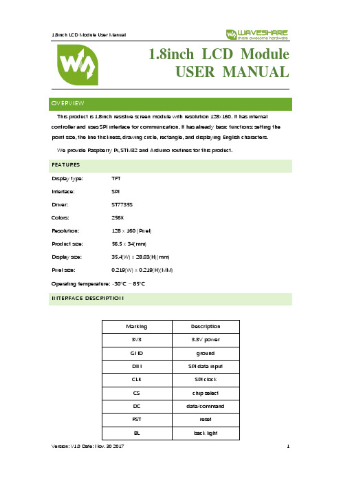
1.8inch LCD ModuleUSER MANUALOVERVIEWThis product is 1.8inch resistive screen module with resolution 128x160. It has internal controller and uses SPI interface for communication. It has already basic functions: setting the point size, the line thickness, drawing circle, rectangle, and displaying English characters.We provide Raspberry Pi, STM32 and Arduino routines for this product.FEATURESDisplay type: TFTInterface: SPIDriver: ST7735SColors: 256KResolution: 128 x 160 (Pixel)Product size: 56.5 x 34(mm)Display size: 35.4(W) x 28.03(H)(mm)Pixel size: 0.219(W) x 0.219(H)(MM)Operating temperature: -30°C ~ 85°CINTERFACE DESCRIPTIONMarking Description3V3 3.3V powerGND groundDIN SPI data inputCLK SPI clockCS chip selectDC data/commandRST resetBL back lightPROGRAM ANALYSIS1.Working principles:ST7735S is 132 x 162 pixels LCD panel, but the product is 128 x 160 pixels LCD display.In the display there are two processes: the horizontal direction scanning – from the 2nd pixel, the vertical direction scanning – from the 1st pixel. So, you can see that positions of pixels in RAM correspond to their actual positions while displaying.The LCD supports 12-bit, 16-bit and 18-bit per pixel input formats. They correspond to RGB444, RGB565 and RGB666 color formats. This routine uses the RGB565 color format, which is commonly used.LCD uses 4-wired SPI communication interface, which can save a lot of GPIO ports and provides fast data transfer to LCD as well.munication protocolNote: there is a difference from traditional SPI. Here we only need display, so sine wires come from slave to host are hidden. The detailed information please refer to datasheet at page 58RESX: Reset. Pull-down while powering on the module. Generally set as 1IM2: data communication mode pin, which define usage of SPICSX: chip selection control pin. If CS=0 – the chip is selectedD/CX: data/command control pin, if DC=0 – command is written, otherwise – data are writtenSDA: transmitted RGB dataSCL: SPI clockThe SPI communication protocol of the data transmission uses control bits: clock phase (CPHA) and clock polarity (CPOL):The value of CPOL determines the level when the serial synchronous clock is in idle state. CPOL=0, that its idle level is 0.The value of CPHA determines the timing of the data bits relative to the clock pulses. CPHA=0, data is sampled at the first clock pulse edge.The combination of these two parameters provides 4 modes of SPI data transmission. The commonly used is SPI0 mode, it is that GPOL=0 and CPHA=0.From the figure above, SCLK begins to transfer data at the first falling edge. 8 bits data are transferred at one clock period. Use SPI0 mode, High bits transfer first, and LOW bits following. DEMO CODERaspberry Pi, STM32 and Arduino programs are provided, wherein Raspberry Pi provides BCM2835, WiringPi and python programs. It implements common graphical functions as drawing dot, line, rectangle, circle, setting their sizes and line with; filling arias, and displaying English characters of 5 common fonts and other display’s functions.Following instructions are offered for you convenienceRASPBERRY1.Hardware connection1.8inch LCD module Raspberry Pi3.3V 3.3VGND GNDDIN MOSI (PIN 19)CLK SCLK (PIN23)CS CE0 (PIN 8)DC GPIO.6 (PIN 22)RST GPIO.2 (PIN13)BL GPIO.5 (PIN18)2.Enable SPI function of the Raspberry Pisudo raspi-configSelect: Advanced Options -> SPI -> yesActivate SPI hardware driver.3.Installation of librariesFore detailed information about libraries installation, please refer to this page:https:///wiki/Libraries_Installation_for_RPiIt is description of WiringPi, bcm2835 and python libraries installation.ageBCM2835 and WiringPi program should be only copied into directory of Raspberry Pi ()by samba or directly copy to the SD card). The following code are compied directly to the user directory of Pi.4.1Usage of BCM2835Run ls command as you can see below:bin: contains “.o” files.We don’t need to change it generallyFonts: contains 5 commonly used fontsPic: contains pictures used for displaying. The resolution of pictures must be 128x128,otherwise they cannot be displayed properly. And the format of pictures must be BMP.Obj: contains object files, like main.c, LCD_Driver.c, DEV_Config.c, LCD_GUI.c and theirheader files.main.c: The mian function. What need to note is that even though there are LCD_ScanDir used to control the direction of scanning, you need not to change it. Because this module is designed for Raspberry Pi, and for compatibility, we don’t recommend you to change it.DEV_Config.c:Definations of Raspberry Pi’s pins and the communication mode.LCD_Driver.c: Drive code of LCD. Need not change generally.LCD_BMP.c: Reading and analyzing BMP files and display themMakefile: This file contains compilation rules. If there are some changes in code, please run make clean to clean all the dependency file and executable files. Then execute make to compile the whole project and generate new executable files.tftlcd_1in8: executable file, generated by command makeTo run the program, you just need to run this command on terminal: sudo ./tftlcd_1in8 4.2WiringPiInput ls command, now you can see following:T he folders is similar to BCM2835’s. The only differences are that:1.WiringPi oprates by read/write the device files of Linux OS. and the bcm2835 is libraryfunction of Raspberry Pi’s CPU, it operates registers directly. Thus, if you have usedbcm2835 libraries firstly, the usage of WiringPi code will be failed. In this case, you just need to reboot the system and try again.2.Due to the first difference, they underlying configuration are different. In DEV_Config.c,use wiringpiPi and the corresponding wiringPiSPI to provide underlay interfaces.The program executed by command sudo ./tftlcd_1in8 as well4.3PythonInput ls command, you can see that:LCD_1in8.py: Driver code of LCDLCD_Config.py: configuration of hardware underlaying interface.Executing program: sudo python LCD_1in8.pyNote: Some of the OS don’t have image libraries. In this case, you can run: sudo apt-get install python-imaging to install the image library.Image is an image processing library of python, represents any image by an image object.Thus, we can create a blank image by new, its size must be same as the display size of LCD.Then draw picture by Draw library, finally, transfer the image to the LCD. Here usingImage.load() too read RGB888 data of pixel, and convert to RGB565. Scanning every pixel then we could get the whole image for displaying. Its most important code is as below:5.Auto-runInitialize autorun in Raspberry Pi by configuring code of /etc/rc.local file:sudo vim /etc/rc.localBefore exit0 add:sudo python /home/pi/python/demo.py &Important: to place the program /home/pi/python/demo.py at the same director, you can input command pwd to get the path. And & character is necessary at the end of command line, otherwise probable need to reinstall the system (impossible terminate the process by pressing ctrl+c, impossible to login with pi user permission).STM32This demo uses XNUCLEO-F103RB developing board and is based on HAT library.1.Hardware connection1.8inch LCD XNUCLEO-F103RBVCC 3V3GND GNDDIN PA7CLK PA5CS PB6DC PA8RST PA9BL PC72.Expected resultProgram the demo into the development Board. Firstly the screen is refreshed completely, then a solid line, dashed line, open circle, solid circle, rectangle, solid torque are drawn and English characters are shown.ARDUINOUNO PLUS Arduino development board is used here.1.Hardware connection1.8inch LCD Arduino3.3V 3V3GND GNDDIN D11CLK D13CS D10DC D7RST D8BL D92.Due to small global memory 2Kb of UNO PLUS, the display can’t work in graphical mode,but the calling method is the same. Just because there is no enough memory, this demo is not provided.COMPATIBLE CODE PORTINGOffered demo is the commonly used programs, which are able to be ported. They can be used with two screens and the difference is only in initialization of them and their sizes.The usage method is defined by macros. In LCD_Driver.h or in LCD.h:#define LCD_1IN44#define LCD_1in8.As the name of the macros, they are used for 1.44inch and 1.8inch LCD separately. To use for one LCD, just need to comment other one.For example://#define LCD_1IN44#define LCD_1IN8Here we use it for 1.8inch LCD, so we comment the 1.44 macro. After saving, Run make clean to remove dependency files, and then run make to generate new executable files.。
TM121SDS01天马12.1寸高对比度液晶屏 色彩鲜艳 TM121SDS01工控液晶屏

二:天马 12.1 寸工业液晶屏 TM121SDS01 结构特征 液晶屏尺寸 点分辨率 像素密度 像素排列 宽高比 点间距 像素间距 面板重量 表面处理 显示区域 可视区域 外观尺寸 外观尺寸 触摸屏 12.1 英寸 800RGB)* 600(SVGA) 82PPI RGB 垂直条状 4:3(宽:高) 0.1025*0.3075mm(横*竖) 0.3075*0.3075mm(横*竖) TBD 雾面 246.0*184.5mm(横*竖) 249.05*188.3mm(横*竖) 279.0*209.0 mm(横*竖) 9.0 (Typ.) mm (厚度) 无
TFT 液晶屏:
TM121SDS01 天马 12.1 寸高对比度液晶屏 色彩鲜艳 TM121SDS01 工ቤተ መጻሕፍቲ ባይዱ液晶屏
一:天马 12.1 寸工业液晶屏 TM121SDS01 基本信息 品 牌 液晶屏型号 工作温度 存储温度 当前生产状态 TIANMA TM121SDS01 -20 ~ 70° C -30 ~ 80° C 量产中
五、天马 12.1 寸工业液晶屏 TM121SDS01 信号接口 信号大类 信号小类 面板电压 面板电流 接口数量 接口脚数 LVDS LVDS (1 ch, 6/8-bit) 3.3V(Typ.) 325mA(Max.) 1pcs 20pins
● 补充说明:以上资料仅供参考,如有某项不准确,可以联系我们客服提供产品的规格资料,产品均以 pdf 规格为准。 TM121SDS01 是采用 LVDS 接口的工业级的高亮度 TFT-LCD 液晶屏。其分辨率为 800(RGB) x 600;可 视范围在 246.0 x 184.5 (mm);对比度是 700:1,本屏的作业温度是-20 -70 (℃),主要用于:军工、 航空、工厂等。
TMS150XG1 23TB天马15寸全视角液晶屏 -TMS150XG1 23TB天马LVDS接口

三:天马 15 寸工业液晶屏 TMS150XG1 23TB 光学特征 显示模式 液晶屏亮度 对比度 显示颜色 显示色域 响应时间 可视角度 白色色度 白场变动 TN,常白显示,透射式 400cd/m2(背光亮度可随意到 1000nits) 600:1 (Typ.) (透射) 262K/16.7M (6-bit / 6-bit + Hi-FRC) 60% NTSC (CIE1931) 3/5(Typ.)(Tr/Td)(ms) 80/80/80/80(Typ.)(CR≥10) (左/右/上/下) X:0.313;Y:0.329 1.25/1.33(Typ./Max.)(9 points)
四、天马 15 寸工业液晶屏 TMS150XG1 23TB 发光系统 灯管位置 光源类型 光源寿命 侧入式光源 WLED 50K (Min.) (小时)
TFT 液晶屏: 单灯电压 单灯电流 接口类型 背光电路 背光电路 17.5/23.1V (Min./Max.) 80Ma(Typ.) 端子 含 LED 驱动器 12.0V(Typ.)(输入电压)
五、天马 15 寸工业液晶屏 TMS150XG1 23TB 信号接口 信号大类 信号小类 面板电压 面板电流 接口数量 接口脚数 LVDS LVDS (1 ch, 6/8-bit) 3.3V(Typ.) 325mA(Typ./Max.) 1pcs 20pins
● 补充说明:以上资料仅供参考,如有某项不准确,可以联系我们客服提供产品的规格资料,产品均以 pdf 规格为准。 TMS150XG1 23TB 用途:主要用于医疗监护,POS 机,广告机显示等工业显示领域。快速响应,分辨率 为:102MS150XG1 23TB 结构特征 液晶屏尺寸 点分辨率 像素密度 像素排列 宽高比 点间距 像素间距 面板重量 表面处理 显示区域 外观尺寸 外观尺寸 触摸屏 15 英寸 1024RGB)* 768(XGA) 85PPI RGB 垂直条状 4:3(宽:高) 0.099*0.297mm(横*竖) 0.297*0.297mm(横*竖) TBD 雾面 304.128*228.096mm(横*竖) 326.5*253.5mm(横*竖) 11.8± 0.3 mm (厚度) 无
天马3.5寸工业液晶屏TM035KDH03规格书-杭州旭虹科技有限公司
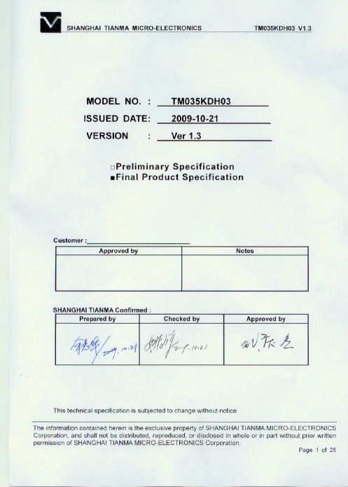
杭州旭虹科技有限公司
SHANGHAI TIANMA MICRO-ELECTRONICS TM035KDH03 V1.3
Table of Contents
Coversheet........................................................................................................................................ 1 Record of Revision............................................................................................................................ 3 1. 2. 3 4 5 6 7 8 9 General Specifications ............................................................................................................... 4 Input/Output Terminals ............................................................................................................... 5 Absolute Maximum Ratings ....................................................................................................... 8 Electrical Characteristics............................................................................................................ 8 Timing Chart............................................................................................................................. 10 Optical Characteristics ............................................................................................................. 17 Environmental / Reliability Tests............................................................................................... 21 Mechanical Drawing................................................................................................................. 22 Packing drawing ...................................................................................................................... 23
模组制程介绍ppt课件

2016
© ©202104 1天4马天微马电子微股电份子有限股公份司有. A限ll公ri司gh.tAs lrl ersiegrhvetsd reserved
1
模组前段工艺流程介绍
一次切割
贴片
二次切割
切割外观 (拨片)
一次电测
4
模组前段工艺流程介绍——切割
• 切割品质
– 好的切割要具备1.Median Crack要深teral Crack要浅 – 刀压是影响垂直裂纹(Median Crack) &水平裂纹(Lateral Crack)的
重要因素 – 刀齿的齿深及角度对切割质量影响重大
径(ID),刀轮的厚度(Thickness)和
刀轮角度(θ)刀轮命名规则为:
OD×ID×Thickness(θ)
天马目前105度-140齿、100度-170
齿和100度-400齿(薄化)三种
微小的裂痕
© 2014 天马微电子股份有限公司. All rights reserved
6
Plasma Cleaning
© 2014 天马微电子股份有限公司. All rights reserved
接触角大
接触角小
(Large Contact Angle) (Small Contact Angle)
表面张力小
表面张力大
(Low Surface Tension) 不良吸水性 (Poor Wettability)
将贴片后的玻璃基板放入密闭的环境(通常是锅炉 状腔体),利用高压(5 kgf/cm2)配合一定的温度(50 度左右),维持一定的时间(20-40分钟),这样就可以 消除小气泡,同时可以增玻璃面板与偏光片间的粘附性 。
天马液晶屏

Display Mode
Surface Treatment(Up Polarizer)
Mechanical Characteristics
Viewing Direction Gray Scale Inversion Direction LCM (W x H x D) (mm) Active Area(mm) With /Without TSP Weight (g) LED Numbers
2 VLED+ P Back light anode
3
GND
P Ground
4
VDD
P Power supply
5
R0
I Data input
6
R1
I Data input
7
R2
I Data input
8
R3
I Data input
9
R4
I Data input
10
R5
I Data input
11
R6
Page 1 of 19
TM050RDH03-40
Table of Contents