BS700
板坯AB700变频器最佳操作法
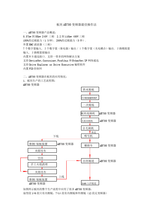
板坯AB700变频器最佳操作法一、AB700变频器产品概述:0.37kw 到55kw 240V 三相 2.2到110kw 400V 三相 150%的过载能力(1分钟). 200%的过载能力(3秒). 外置EMC 滤波器(三相)7个数字量输入.2个数字量(继电器)输出/1个数字量(光电耦合)输出.2路模拟量输入.2路模量拟输出内置RS通迅接口.支持一带多的网络解决方案支持DeviceNet,Controinet,Profibus 和EtherNet/IP 网络通迅 支持Drive Explorer or Drive Executive 编程软件 内置PID 控制环二、AB700变频器在板坯的应用情况: 1.板坯生产的工艺流程图:AB700变频器如图所示板坯的整个生产流程中应用了很多AB700变频器,扇型段1-6段只有内侧辊,7-14段有内侧辊和外侧辊(12段无变频器)变频器变频器变频器AB700变频器扇型段变频器都采用闭环矢量控制方式,用编码器作为速度反馈。
1-8段抱闸上位机和变频器都可以控制。
扇型段以后切割辊道、去毛刺辊道、推钢/垛板装置、横移车、出坯辊道变频器都采用开环无速度传感器矢量控制,且没有抱闸。
扇型段设备情况:AB700变频器的菜单结构:用户显示诊断参数设备选择存储器存储起动Preferences通过HIM查看和编辑参数是①初始显示画面按ESC进入主菜单,在主菜单中按向上向下箭头键,滚动到“PARAMETER(参数)”②按回车键,在顶行显示“FGP FILE(文件),在它下面显示三个开头的文件。
③按向上或向下箭头在文件列中滚动。
④按回车键选择文件,文件的下面显示文件所在的组。
⑤重复步骤3和4选择某个组的某个参数。
出现参数的数值屏幕。
⑥按回车键进入编程模式。
⑦按向上箭头或向下箭头编辑参数值。
如果有需要,可以按SEL键选择不同的数字,字符或位,允许修改的数字或位变成高亮。
⑧按回车键保存数值,如果想取消这次修改,按ESC键。
吊车司机考试题精品资料

起重机械安全考核复习题及参考答案(可选其中的进行考试)一、判断题(对的划",错的划X)I、起重机取物装置本身的重量一般都不应包括在额定起重量中。
()1、X7、滑轮有裂纹或轮缘破损应报废。
()7.V8滑轮槽不均匀磨损达3mn应报废。
()8"9、新更换的钢丝绳应与原安装的钢丝绳同类型、同规格。
()"II、司机室位于大车滑线端时,通向司机室的梯子和走台与滑线间应设置安全防护板。
()11、"12、露天工作的起重机,其电器设备应设置防雨罩。
()12、"16、桥式起重机司机室应设在导电滑线的一侧。
()16、X30、起升机构可以使用编结接长的钢丝绳。
()30、X31、变幅机构不得使用编结接长的钢丝绳。
()31、"32、钢丝绳尾端在卷筒上固定,单层缠绕时通常采用压板。
()"33、齿轮减速器在使用中主要损坏形式是齿轮失效。
()33、"35、起重机械的起升机构经常使用的是同向捻结构钢丝绳。
()X36、在非正常使用状态下,超载是钢丝绳破断的主要原因。
()"37、在正常使用情况下,钢丝绳绳股中的钢丝的断裂是逐渐产生的。
()37、"39、减速器正常工作时,箱体内必须装满润滑油。
()39、X 40、钢丝绳绳芯中含有油脂,当绳受力时起润滑钢丝的作用。
(45、违规操作是发生起重伤害事故的主要原因。
()45、“47、如触电地点附近没有电源开关或插销,可用其它利器(如斧头、刀具)将电源线切断。
()47、X48、起重机发生火灾的原因主要由于电器设备在运行中超过额定负荷造成线路短路过热和打火花造成。
()48、"二、填空题1、起重机基本参数是表征起重机 ______ 的。
1、特性2、起重机两端梁车轮踏面 ______ 间的距离称为起重机的跨度。
2、中心线5、起重机轮按轮缘可分为 _____ 轮缘、________ 轮缘和 ________ 轮缘三种。
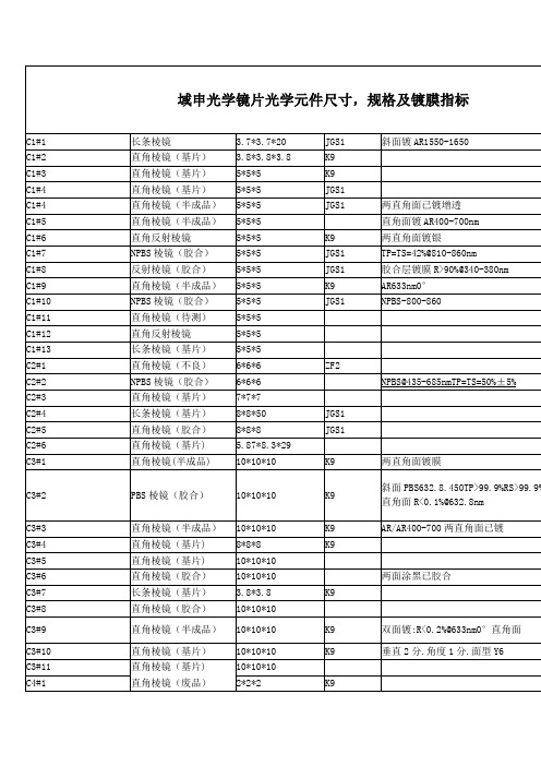
光学元件棱镜滤光片等的规格尺寸镀膜要求
C13#
直角棱镜(待测)
10*10*10
5
C13#1
分光棱镜(胶合)
20*20*20
R/T=7/3@400-700nm
6
C13#2
NPBS棱镜(半成品)
20*20*20
NPBS@450-650nmTP=TS45±5%@450-650nm
20
C13#3
NPBS棱镜(胶合)
25.4*25.4*25.4
4
C18#1
直角棱镜(半成品)
10*10*10
两直角面已镀
4
C18#2
次品
17.8*10*8.3
1
C18#3
PBS棱镜
20*20*20
4
C18#
PBS棱镜(胶合)
20*20*20
45°TP>95%RS>99%PBS580nm
1
C18#
分光棱镜
20*20*20
可见光R:T=1:1@400-700
8
C18#
NPBS@400-700nmTP=TS=9:1
2
C10#5
NPBS棱镜
20*20*20
K9
T/R=5/5 400-700nm
2
C10#6
分光棱镜
20*20*20
K9
斜面已镀分光@1064nm
6
C10#7
反射棱镜
20*20*20
K9
一直角面镀AR@632.8nm
5
C10#8
NPBS棱镜
20*20*20
K9
两面毛,已胶合9组
9
C5#3
直角棱镜(半成品)
15*15*15
AR/AR400-700两直角面已镀
香港百特BS700--便携式 高灵敏度红外热像仪
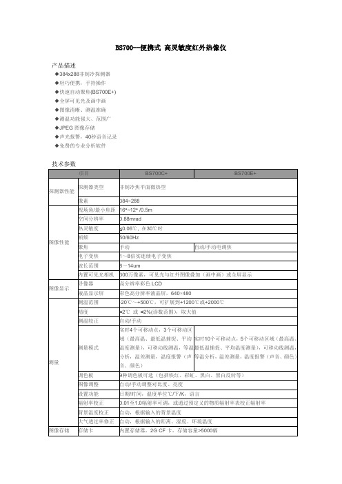
BS700--便携式高灵敏度红外热像仪产品描述◆384x288非制冷探测器◆轻巧便携,手持操作◆快速自动聚焦(BS700E+)◆全屏可见光及画中画◆图像清晰、测温准确◆测温功能强大、范围广◆JPEG图像存储◆声光报警,40秒语音记录◆免费的专业分析软件技术参数项目BS700C+ BS700E+ 探测器性能探测器类型非制冷焦平面微热型像素384×288图像性能视场角/最小焦距16°×12° /0.5m空间分辨率0.88mrad热灵敏度≤0.06℃, 在30℃时帧频50/60Hz聚焦手动自动/手动电调焦电子变焦1~8倍实连续电子变焦波长范围8~14um内置可见光相机300万像素,可见光与红外图像叠加(画中画)或全屏显示图像显示寻像器高分辨率彩色LCD液晶显示屏彩色高分辨率液晶屏,640×480测量测温范围-20℃~+500℃,可扩展到+1200℃或+2000℃精度±2℃或±2%(读数范围),取大值测温较正自动/手动测量模式实时4个可移动点,3个可移动区域(最高温、最低温捕捉、平均温度测量),可移动线测温,等温分析,温差测量,温度报警(声音、颜色)实时10个可移动点,5个可移动区域(最高温、最低温捕捉、平均温度测量),可移动线测温,等温分析,温差测量,温度报警(声音、颜色)调色板9种调色板可选(包括铁红、彩虹、黑白、黑白反转等)图像调整自动/手动调整对比度、亮度设置功能日期/时间,温度单位℃/℉/K,语言辐射率校正0.01至1.0辐射率可调,或通过预定义的物质辐射率表校正辐射率背景温度校正自动,根据输入的背景温度大气透过率修正自动,根据输入的距离、湿度、环境温度图像存储存储卡内置存储器,2G CF卡,存储容量>5000幅存储方式手动/自动单帧图像存储文件格式JPEG格式,带14位测量数据图像可见光图像格式JPEG格式或随图像一同存储(画中画)语音注释40秒语音记录,随图像一同存储(内置麦克风)图像处理图像平均(∑2、∑4、∑8、∑16),图像滤波激光指示激光指示器二级,1mW/635nm红色电源系统电池类型锂电池,可充电电池工作时间2小时连续工作充电类型智能充电器或电源适配器(可选)本机充电省电模式有外接电源10-15V DC环境参数操作温度-15℃- +50℃防护等级IP54湿度≤90%(非冷凝)物理特性重量 1.83Kg/1.69Kg尺寸305mm×130mm×135mm接口电源接口有音频输出有视频输出PAL/NTSC/ VGAUSB 图像,测量数据,语音传送至计算机转载文章《香港百特BS700--便携式高灵敏度红外热像仪》请注明出处: 谢谢!下载地址:/BETTER/hongwairexiangyi/2013/0703/BS700.html。
BS700
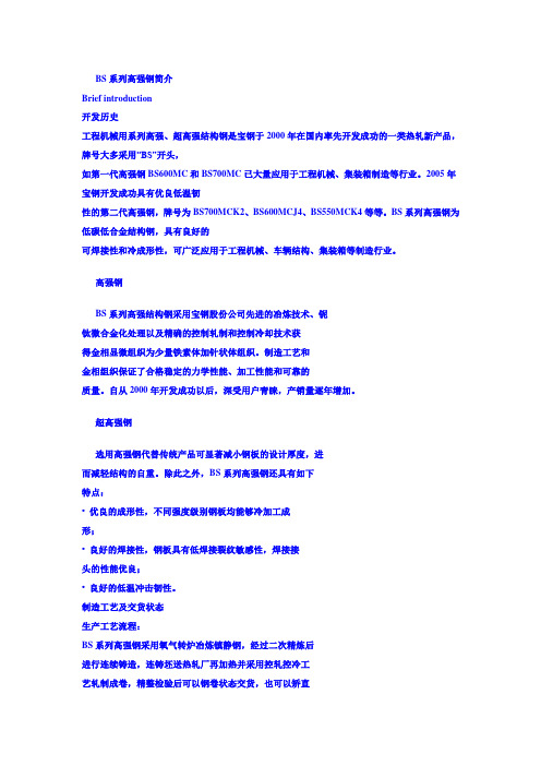
BS系列高强钢简介Brief introduction开发历史工程机械用系列高强、超高强结构钢是宝钢于2000年在国内率先开发成功的一类热轧新产品,牌号大多采用“BS”开头,如第一代高强钢BS600MC和BS700MC已大量应用于工程机械、集装箱制造等行业。
2005年宝钢开发成功具有优良低温韧性的第二代高强钢,牌号为BS700MCK2、BS600MCJ4、BS550MCK4等等。
BS系列高强钢为低碳低合金结构钢,具有良好的可焊接性和冷成形性,可广泛应用于工程机械、车辆结构、集装箱等制造行业。
高强钢BS系列高强结构钢采用宝钢股份公司先进的冶炼技术、铌钛微合金化处理以及精确的控制轧制和控制冷却技术获得金相显微组织为少量铁素体加针状体组织。
制造工艺和金相组织保证了合格稳定的力学性能、加工性能和可靠的质量。
自从2000年开发成功以后,深受用户青睐,产销量逐年增加。
超高强钢选用高强钢代替传统产品可显著减小钢板的设计厚度,进而减轻结构的自重。
除此之外,BS系列高强钢还具有如下特点:• 优良的成形性,不同强度级别钢板均能够冷加工成形;• 良好的焊接性,钢板具有低焊接裂纹敏感性,焊接接头的性能优良;• 良好的低温冲击韧性。
制造工艺及交货状态生产工艺流程:BS系列高强钢采用氧气转炉冶炼镇静钢,经过二次精炼后进行连续铸造,连铸坯送热轧厂再加热并采用控轧控冷工艺轧制成卷,精整检验后可以钢卷状态交货,也可以矫直切板后以钢板状态交货。
交货状态:BS系列高强钢基本采用轧态(TMCP)交货。
所示,超出规格范围可与宝钢热轧高强钢产销研小组联系(附后)。
牌号Steel grade可供厚度Thickness,mm可供宽度Width,mm可供长度Length,mmBS550- 2.5-16 850-1750 2000-12000BS600- 2.5-16 850-1750 2000-12000BS700- 2.5-14 850-1600 2000-12000BS960- 4-10 950-1200 2000-12000牌号及可供规格范围Product range of dimensions宽度(width), mm181014617913516812421571131800 900 1000 1100 1200 1300 1400 1500 1600 1700 1800厚度(Thickness), mm BS550 BS600 BS700 BS9602工程机械用高强度热连轧结构钢High Strength Cold Forming Hot-rolled Steel供货技术条件及产品性能实绩Delivery ConditionB S 7 0 0 MC K 2K2:-20℃冲击值不小于40JJ4:-40℃冲击值不小于27JK4:-40℃冲击值不小于40J控轧控冷(非调质)生产的冷成型用钢宝钢结构钢屈服强度等级3力学*货标准牌号Steel Grade厚度Thicknessmm拉伸试验(2)Tensile test冲击试验(3)CVN Impact test180°弯曲试验Bending test方向(1) 屈服强度Re, MPa抗拉强度Rm, MPa伸长率A5, %方向(1) 温度Temp., ℃冲击值IE, J方向(1) 弯心直径DiameterBS550MCK4 ≤16 T ≥550 ≥600 ≥18 L -20 ≥40 T d = 2a BS600MCJ4<10T≥600 ≥680 ≥15L -40 ≥27 T d = 2a10-16 ≥580 ≥680 ≥15BS700MCK23-8T≥700 750-950 ≥15L -20 ≥40 T d = 2a>8 ≥680 750-950 ≥15BS900MCJ4 3-10 L ≥900 ≥950 ≥10 L -40 ≥27 T d = 3a BS960MCJ4 3-10 L ≥960 ≥980 ≥10 L -40 ≥27 T d = 3a S500MC ≤16 L ≥500 550-700 ≥14 / / / T d = 1aS550MC ≤16 L ≥550 600-760 ≥14 / / / T d = 1.5aS600MC(BS600MC)≤16 L ≥600 650-820 ≥13 / / / T d = 2aS650MC ≤16 L ≥650 700-880 ≥12 / / / T d = 2aS700MC(BS700MC)≤6 L ≥700 750-950 ≥12 / / / T d = 2a注:(1) T= Transverse,试样方向垂直于轧制方向; L=longitude,试样方向平行于轧制方向。
B700、D700和T700 ASHCROFT

© Ashcroft Inc., 250 East Main Street, Stratford, CT 06614 USA, Tel: 203-378-8281, Fax; 203-385-0408, All sales subject to standard terms and conditions of sale. b-d-t-700_switch_im_RevC_(009-10120-ATEX) 11-05-181. Installation Requirements • T he equipment may be used with flammable gases and vapors with apparatus groups IIC and with temperature class T6 in the ambient temperature range –20ºC to +60ºC.• B 7 and D7 Switches, Process Temperature: – 20 to 60°COther temperature limits are possible with different diaphragm materials • I nstallation shall be carried out by suitably-trained personnel in accordance with the applicable code of practice e.g. IEC/EN 60079-14.• R efer to appropriate datasheet for materials of construction and te c hnical information.• T hese switches are precision instruments and should never be left with internal components exposed. During installation insure that covers are in place and conduit openings are closed except when actually working on the switches.• T o minimize the risk of injury, the switches must be installed according to the required safety and electrical codes.• T o attain the degree of protection listed on the switch it may be necessary to add required conduit fittings.• T he switch must be protected from moisture, shock and/or extreme vibration.• M ounting position: Switch can be mounted in any position. It is recommended that unit be set in intended operating position.• R efer to tag on product to for product catalog number, electrical rating, pressure/temperature range, wetted materials, proof pres-sure/proof temperature rating and switch deadband.2. Cautions • T he certification of this equipment relies upon the following mate-rials used in its construction: aluminum and stainless steel. If the equipment is likely to come into contact with aggressive sub-stances, then it is the responsibility of the user to take suitable precautions that prevent it from being adversely affected, thus ensuring that the type of protection provided by the equipment is not compromised. For compatibility questions contact Ashcroft.• A lways install the cover after wiring the switch and before power is supplied.• B efore removing the cover in hazardous areas be sure there is no explosive atmosphere present and the power supply is turned off.• F or ATEX/IEC approved switches all safety locking devices and electrical earthing must be installed or connected before operat-ing.• N ever carry a temperature switch by holding only the stem, bulb or capillary.• D o not push any foreign objects (ex. Screwdrivers) against the diaphragm.• Do not exceed ranges, current and/or voltage limits.3. Mounting • T hree holes external to the enclosure for surface mounting. Location of these holes is shown in the general dimension drawing.• U nits may also be mounted directly on the pressure line using the pressure connection. When tightening control to pressure line, always use the wrench flats or hex on the lower housing.4. Electrical Connections • B efore operating the switch all conduit entries and/or junctionboxes need to be closed according to the required safety andelectrical codes. a ) S tandard product has two ¾ NPT conduit holes one of whichis fitted with a suitably certified blanking device. ¾ NPT conduit holes can be adapted with suitably certified reducers. b) ATEX/IEC approved cable glands can be used.• I t is recommended that Teflon tape or other sealant be used on conduit, bushing, gland or plug threads to ensure integrity of the enclosure.• O nly trained and skilled personnel are allowed to install the wires to the electrical terminals of the switch.• C able couplers, glands and conduit connectors must have the correct electrical approvals.• A lways follow safety and electrical regulations when connecting these devices.• T he system ground of the device is marked with a green colored screw and/or by the ground symbol.• A TEX approved switches have and external ground screw that must be connected.• Micro switch terminals and wire color codes: NO (Normally Open) Blue NC (Normally Closed) Red C (Common) White • S PDT – Wire directly to the switch according to circuit require-ments.• 2 SPDT – Wire to front switch terminal block (left) and rear switch terminal block (right) as marked. Strip insulation 5⁄16˝, insert in prop-er terminal connector and tighten clamping screw to secure.MICRO SWITCH CODEELECTRICAL RATING SingleDualVa cVdc 20 61 15A, 250V 0.4A, 120V 21 65 5A, 250V 22 67 5A, 250V 2.5A, 28V 23 N/A 22A, 250V 24 64 15A, 480V 0.25A, 250V 25 N/A 10A, 250V 10A, 250V 26 62 15A, 250V 0.4A, 120V27 63 15A, 250V 28 N/A 15A, 250V 29 N/A 15A, 250V 31 70 1A, 250V 50mA, 60V 32 68 11A, 250V 5A, 30V42 71 1A, 125V 50 N/A 15A, 250V35N/A10A, 250V0.3A, 250VTABLE 1: MICRO SWITCH ELECTRICALRATINGSThis product complies with the following standards: IECEx ATEX IEC 60079-0:2011 Ed 6 EN 60079-0:2012 IEC 60079-1:2014 Ed 7 EN 60079-1:2014 IEC 60079-31:2013 IEC 60079-31:2013© Ashcroft Inc., 250 East Main Street, Stratford, CT 06614 USA, Tel: 203-378-8281, Fax; 203-385-0408, All sales subject to standard terms and conditions of sale. b-d-t-700_switch_im_RevC_(009-10120-ATEX) 11-05-185. Adjustment of Setpoin Note – As indicated below, adjustment of setpoint is made by use of 7⁄8˝ nut. Precision switch element mounting screws and bracket adjusting screw are factory sealed and should not be tampered with.B700 Series – A single setpoint adjustment nut (7/8˝) is located centrally at the bottom on the inside of the enclosure.For accurate setpoint calibration, mount the switch on a calibration stand, a pump or catalog No. 1305 deadweight gauge tester. A suitable reference standard such as an ASHCROFT Duragauge or Test Gauge is necessary to observe convenient changes in pressure.As received, the pressure switch will normally be set to approx-imately 90% of the indicated range. Pressurize the s ystem torequired setpoint and turn the adjustment nut until switch changes mode. Direction of turning is indicated on a label affixed to the inside of the switch enclosure. When setpoint has been achieved raise and lower pressure to insure that setpoint is correct.After installation of the switch replace cover to insure electrical safety and to protect internal parts from the environment.Note – Since vacuum models are already above setpoint at atmo-sphere, the Normally Open (NO) circuit will be closed as received.D700 Series – A single setpoint adjustment nut (7/8˝) is located centrally at the bottom on the inside of the enclosure.The direction of turning is indicated on a label affixed to the inside of the switch enclosure.A typical calibration procedure would be as follows: Static Working Pressure - 600 psig Adjustable Differential Range - 5/200 psid Differential Setpoint - 150 psi above static working pressure.Simultaneously raise the high and low side pressure to 600 psig. Maintain the low side pressure at 600 psig. Raise the high side pressure to 750 psig to obtain 150 psi differential.Turn the adjustment nut until the switch changes mode at 150 psi differential. When the setpoint has been achieved, raise and lower the high side pressure to ensure that the differential setpoint is correct.D700 Series (low range differential) – A single setpoint adjust-ment nut (7⁄8˝ ) is located centrally at the bottom on the inside of the enclosure.The direction of turning is indicated on a label affixed to the inside of the switch enclosure. XG5 switches have a setpoint indication scale adjacent to the adjustment nut. To adjust the switch, align the top of the adjustment nut hex with the indicator line on the scale. Do not force adjustment or attempt to ex-ceed the maxi-mum setting shown on the scale or nameplate.For accurate setpoint calibration or for switches without a scale mount the switch on a calibration stand so that the HIGH and LOW pressures expected under operating conditions may be obtained. Suitable reference standards are necessary for each pressure.Note – During calibration an approximate setpoint under operating conditions can be obtained by setting the operating point with the low side open to atmosphere. A final setpoint adjustment can be made after installation.Apply LOW pressure. Then apply HIGH pressure to the required setpoint and turn the adjustment nut until the switch operates. When the setpoint has been achieved, raise and lower HIGH pres-sure to ensure that the differential pressure between the HIGH and LOW pressures is correct.After installation of the switch, replace the cover to ensure electri-cal safety and to protect the internal parts from the e nvironment.T700 Series – A single setpoint adjustment nut (7⁄8˝ ) is located cen-trally at the bottom on the inside of the enclosure.The bulb of the switch should be immersed in a bath at the desired setpoint temperature. Optimum performance will be obtained if the bulb is fully immersed. Allow five minutes for initial stabilization.As received, the temperature switch will normally be set to approx-imately 90% of the indicated range. After stabilization, turn the adjustment nut until switch changes mode. Direction of turning is indicated on a label affixed to the inside of the switch enclosure. When setpoint jas been achieved raise and lower temperature to insure that the setpoint is correct.After installation of the switch replace cover to insure electrical safety and to protect internal parts from the environment.B750, D750 and T750 Variable Deadband Switches – Deadband is varied by rotating the wheel on the precision switch. Whenviewed from the front of the enclosure, rotation to the left increases deadband – rotation to the right decreases deadband. Letters on the wheel may be used as a reference. Deadbands obtainable will vary from 0.5% to 9% of pressure or temperature range depending on range segment and type of diaphragm.Adjustment of Setpoint – As received, the switch will normally be set to approximately 90% of range. Rotate the wheel on the MICRO SWITCH all the way to the right; this will provide small-est deadband. Pressurize, or increase bath temperature, to the required setpoint and turn the adjustment nut until the switch changes mode. Lower the pressure to reset the switch. Rotate the wheel on the MICRO SWITCH until the desired deadband is obtained. The upper setpoint will be changing upward with this adjustment. Lower the pressure to reset the switch. Then increase the pressure to the desired setpoint and turn the adjusting nut until the switch changes mode. Lower the pressure and check reset-point and deadband.6. Specific Conditions of Use • P rior to use, the equipment shall be subjected to a pressure test, which shall be based on the process pressure of the associated system. If available, the test shall be conducted in accordance with the requirements of an applicable industry standard. The pressure shall be applied from the system side of the diaphragm. It must be proven that there is no leakage of the test medium into the flameproof enclosure and that the flameproof enclosure does not become pressurized above ambient atmospheric pressure.• E poxy coated enclosures are non-conducting and may generate an ignition-capable level of electrostatic charges under certain extreme conditions. The user should ensure that the equipment is not installed in a location where it may be subjected to external conditions (such as high-pressure steam) which might cause a build-up of electrostatic charges on non-conducting surfaces. Additionally, cleaning of the equipment should be done only with a damp cloth. • S witch vent must not be used nor blocked.• I n accordance with clause 5.1 of IEC/EN 60079-1 the critcal dimensions of the flamepaths are:• Never use aggressive solvents.• Do not use high-pressure water to clean the switch.8. Maintenance/Troubleshooting• All ASHCROFT switches require little or no maintenance.• I nspection and maintenance of this equipment shall be carried out by suitably trained personnel in accordance with the applica-ble code of practice e.g. IEC/EN 60079-17.• Be sure that the case is closed at all times.• W hen the switch is exposed to process media that may hard-en and/or build up in the pressure port, the switch should be removed and cleaned as needed.• I f the switch does not function, only trained and skilled personnel should check on the wiring, power supply and/or mounting.• I f the problem cannot be solved, do not attempt to repair, please contact Ashcroft or Ashcroft distributor.© Ashcroft Inc., 250 East Main Street, Stratford, CT 06614 USA, Tel: 203-378-8281, Fax; 203-385-0408, All sales subject to standard terms and conditions of sale. b-d-t-700_switch_im_RevC_(009-10120-ATEX) 11-05-18。
各国安规标志
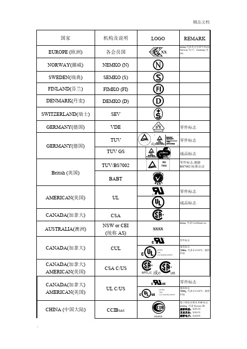
xxxx
xxxx:代表Certificate no.
CANADA(加拿大)
CUL
零件标志
成品标志
7Z00:代表E131875,康舒科技
CANADA(加拿大) AMERICAN(美国)
CSA C/US
或
CANADA(加拿大) AMERICAN(美国)
UL C/US
零件标志
成品标志
7Z00:代表E131875,康舒科技
SEV
GERMANY(德国)
VDE
零件标志
GERMANY(德国)
TUV
或
零件标志
TUV GS
成品标志
British (英国)
TUV/BS7002
零件标志,根据BS7002标准认证
BABT
AMERICAN(美国)
UL
零件标志
成品标志
CANADA(加拿大)
CSA
AUSTRALIA(澳洲)
NSW or CEI
CHINA (中国大陆)
CCIBS&E
xxxxx
进口商品安规及EMI标志
xxxxx:代表Factory ID
康舒科技:S20134
艾克贝尔:S20135
康舒电子:S20295
CCEE
xxxxx
内销长城标志
xxxxx:代表Certificate no.
RUSSIA (俄罗斯)
GOST
EUROPEAN COMMUNITY
SII
IRELAND (爱尔兰)
NSAI
YUGOSLAVIA
(南斯拉夫)
FIS
AUSTRIAN (奥地利)
öVE
SINGAPORE (新加坡)
变压器磁芯承认标准
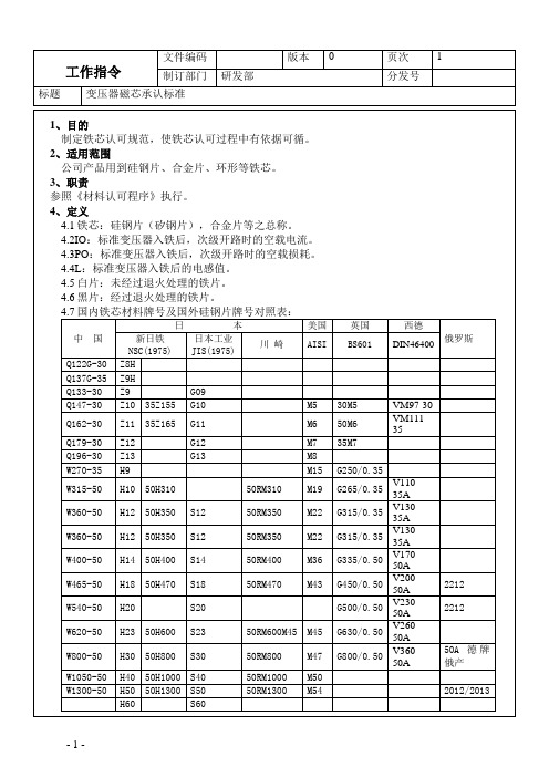
制定铁芯认可规范,使铁芯认可过程中有依据可循。
2、适用范围
公司产品用到硅钢片、合金片、环形等铁芯。
3、职责
参照《材料认可程序》执行。
4、定义
4.1铁芯:硅钢片(矽钢片),合金片等之总称。
4.2IO:标准变压器入铁后,次级开路时的空载电流。
4.3PO:标准变压器入铁后,次级开路时的空载损耗。
4.4L:标准变压器入铁后的电感值。
1.5W
EI-86
Z11A
0.35
700T
26#/0.45
29X43
123
220V
50HZ
45mA
2.0W
EI-86H
Z11A
0.35
700T
26#/0.45
29X43
123
220V
50HZ
45mA
1.6W
EI-86
Z23A
0.50
700T
26#/0.45
29X43
86
220V
50HZ
40mA
4.5W
型号
A±0.2
B±0.2
C±0.2
D±0.2
E±0.2
F±0.2
H1±0.2
H2±0.2
I±0.2
Φ1±0.05
Φ2±0.05
厚(δ)度±0.02
EI-14
14
8.75
3.5
3.5
1.75
1.75
0.35/0.5
EI-16
16
12
4
4
2
2
0.35/0.5
EI-19
19
12.5
5
4.5
2.5
2.5
- 1、下载文档前请自行甄别文档内容的完整性,平台不提供额外的编辑、内容补充、找答案等附加服务。
- 2、"仅部分预览"的文档,不可在线预览部分如存在完整性等问题,可反馈申请退款(可完整预览的文档不适用该条件!)。
- 3、如文档侵犯您的权益,请联系客服反馈,我们会尽快为您处理(人工客服工作时间:9:00-18:30)。
BS系列高强钢简介Brief introduction开发历史工程机械用系列高强、超高强结构钢是宝钢于2000年在国内率先开发成功的一类热轧新产品,牌号大多采用“BS”开头,如第一代高强钢BS600MC和BS700MC已大量应用于工程机械、集装箱制造等行业。
2005年宝钢开发成功具有优良低温韧性的第二代高强钢,牌号为BS700MCK2、BS600MCJ4、BS550MCK4等等。
BS系列高强钢为低碳低合金结构钢,具有良好的可焊接性和冷成形性,可广泛应用于工程机械、车辆结构、集装箱等制造行业。
高强钢BS系列高强结构钢采用宝钢股份公司先进的冶炼技术、铌钛微合金化处理以及精确的控制轧制和控制冷却技术获得金相显微组织为少量铁素体加针状体组织。
制造工艺和金相组织保证了合格稳定的力学性能、加工性能和可靠的质量。
自从2000年开发成功以后,深受用户青睐,产销量逐年增加。
超高强钢选用高强钢代替传统产品可显著减小钢板的设计厚度,进而减轻结构的自重。
除此之外,BS系列高强钢还具有如下特点:• 优良的成形性,不同强度级别钢板均能够冷加工成形;• 良好的焊接性,钢板具有低焊接裂纹敏感性,焊接接头的性能优良;• 良好的低温冲击韧性。
制造工艺及交货状态生产工艺流程:BS系列高强钢采用氧气转炉冶炼镇静钢,经过二次精炼后进行连续铸造,连铸坯送热轧厂再加热并采用控轧控冷工艺轧制成卷,精整检验后可以钢卷状态交货,也可以矫直切板后以钢板状态交货。
交货状态:BS系列高强钢基本采用轧态(TMCP)交货。
所示,超出规格范围可与宝钢热轧高强钢产销研小组联系(附后)。
牌号Steel grade可供厚度Thickness,mm可供宽度Width,mm可供长度Length,mmBS550- 2.5-16 850-1750 2000-12000BS600- 2.5-16 850-1750 2000-12000BS700- 2.5-14 850-1600 2000-12000BS960- 4-10 950-1200 2000-12000牌号及可供规格范围Product range of dimensions宽度(width), mm181014617913516812421571131800 900 1000 1100 1200 1300 1400 1500 1600 1700 1800厚度(Thickness), mm BS550 BS600 BS700 BS9602工程机械用高强度热连轧结构钢High Strength Cold Forming Hot-rolled Steel供货技术条件及产品性能实绩Delivery ConditionB S 7 0 0 MC K 2K2:-20℃冲击值不小于40JJ4:-40℃冲击值不小于27JK4:-40℃冲击值不小于40J控轧控冷(非调质)生产的冷成型用钢宝钢结构钢屈服强度等级3力学*货标准牌号Steel Grade厚度Thicknessmm拉伸试验(2)Tensile test冲击试验(3)CVN Impact test180°弯曲试验Bending test方向(1) 屈服强度Re, MPa抗拉强度Rm, MPa伸长率A5, %方向(1) 温度Temp., ℃冲击值IE, J方向(1) 弯心直径DiameterBS550MCK4 ≤16 T ≥550 ≥600 ≥18 L -20 ≥40 T d = 2a BS600MCJ4<10T≥600 ≥680 ≥15L -40 ≥27 T d = 2a10-16 ≥580 ≥680 ≥15BS700MCK23-8T≥700 750-950 ≥15L -20 ≥40 T d = 2a>8 ≥680 750-950 ≥15BS900MCJ4 3-10 L ≥900 ≥950 ≥10 L -40 ≥27 T d = 3a BS960MCJ4 3-10 L ≥960 ≥980 ≥10 L -40 ≥27 T d = 3a S500MC ≤16 L ≥500 550-700 ≥14 / / / T d = 1aS550MC ≤16 L ≥550 600-760 ≥14 / / / T d = 1.5aS600MC(BS600MC)≤16 L ≥600 650-820 ≥13 / / / T d = 2aS650MC ≤16 L ≥650 700-880 ≥12 / / / T d = 2aS700MC(BS700MC)≤6 L ≥700 750-950 ≥12 / / / T d = 2a注:(1) T= Transverse,试样方向垂直于轧制方向; L=longitude,试样方向平行于轧制方向。
(2) 拉伸试样采用短比例标距。
标距,屈服强度采用上屈服强度,屈服现象不明显时,采用RP0.2。
(3) 冲击试样采用夏比V型缺口试样,表中冲击值为一组三个试样的平均值,表中冲击值适用于10×10×55标准尺寸试样,当板厚<12mm采用5mm或7.5mm厚度冲击试样时,表中冲击值等比例减小。
4工程机械用高强度热连轧结构钢High Strength Cold Forming Hot-rolled Steel典型力学性能实绩宝钢BS系列高强钢于2000年研发成功以来,已批量生产约40万吨,实物性能检验值的80%以上在表列波动范围以内。
牌号Steel grade厚度Thickness, mm屈服强度Re, MPa抗拉强度Rm, MPa伸长率A5, %冲击值IE, JBS550MCK4 6-12 560-645 645-740 16-26 120-280BS600MCJ42.5-(10) 600-670 680-780 15-23 -10-16 600-660 700-760 16-21 120-2703-8 700-860 780-920 15-21 40-100(8)-14 685-820 790-900 15-21 60-150BS960MCJ4 4-10 960-1050 1050-1080 11-15 100-140BS600MC 3-16 640-720 700-790 17-26 -BS700MC 2.5-8 680-810 750-880 14-23 -化学成分,wt%强度级别牌号Steel GradeC Si Mn P S Alt B550 BS550MCK4 ≤0.12 ≤0.50 ≤1.60 ≤0.015 ≤0.005 ≥0.015 -600BS600MCJ4 ≤0.12 ≤0.50 ≤1.60 ≤0.015 ≤0.005 ≥0.015 -BS600MC ≤0.12 ≤0.50 ≤2.0 ≤0.020 ≤0.010 ≥0.015 -700BS700MCK2 ≤0.12 ≤0.60 ≤2.10 ≤0.025 ≤0.010 ≥0.015 -BS700MC ≤0.12 ≤0.60 ≤2.10 ≤0.025 ≤0.015 ≥0.015 -(900) (BS900MCJ4) ≤0.12 ≤0.50 ≤1.60 ≤0.015 ≤0.005 ≥0.015 ≤0.003 960 BS960MCJ4 ≤0.12 ≤0.50 ≤1.60 ≤0.015 ≤0.005 ≥0.015 ≤0.003注:根据强度要求,可加入Nb、V、Ti、Cr、Mo等合金元素。
According to the strength, Nb, V, Ti, Cr and Mo may be added.5焊接宝钢BS系列热连轧高强钢通过低碳低合金设计降低钢的碳当量和焊接裂纹敏感指数,并采用先进的冶炼装备技术结合微合金强化技术,获得良好的可焊接性。
良好的焊接性—碳当量及焊接裂纹敏感性指数牌号Steel grade碳含量实绩C, %Ceq焊接裂纹敏感性指数实绩PcmBS550MCK4 ≤0.08 ≤0.49 ≤0.22BS600MCK4 ≤0.08 ≤0.45 ≤0.20BS700MCK2 ≤0.08 ≤0.47 ≤0.21BS960MCJ4 ≤0.10 ≤0.52 ≤0.24BS600MC ≤0.08 ≤0.45 ≤0.20BS700MCJ4 ≤0.08 ≤0.47 ≤0.21Ceq=C+Mn/6+(Cu+Ni)/15+(Cr+Mo+V)/5Pcm=C+Si/30+(Mn+Cu+Cr)/20+Ni/60+Mo/15+V/10+5B —焊接裂纹敏感性试验采用搭接接头拘束焊接裂纹试验(CTS)测定了BS高强钢焊接裂纹敏感性,结果表明各项裂纹发生率均为0%。
证明BS系列高强钢在0℃以上进行各种焊接加工时,不易产生焊接裂纹。
—接头的硬度BS高强钢焊接接头的最大硬度小于HV350。
高强钢的焊接热影响区存在一个比较窄的软化区。
建议尽可能采用小热输入、快速焊接为宜,以减小软化区的宽度。
焊接工艺参数环境温度大于0℃时,BS高强钢板不需预热就可直接进行焊接,不易产生焊接冷裂纹。
推荐使用MAG焊接,推荐焊接保护气体为80%Ar+20%CO2;气体流量18~25 l/min。
对于推荐的焊丝适用于全位置焊接,当垂直位置焊接时,推荐采用上向焊接方法,这样可避免焊接缺陷产生。
热轧高强钢适用于多种接头型式的焊接,常用的接头型式有:对接接头、角接接头和搭接接头;常用的坡口型式有:I型坡口,V型坡口和双V型坡口型式。
在焊接时,若出现未焊透时,应检查是否间隙太小,是否电弧没有垂直钢板表面。
对于打底焊时,可采用较小焊接参数的熔滴过渡形式,即小电流,小电压,快速焊;对于特别重要的结构件,也可考虑采用TIG焊打底。
对于定位焊接,为了防止出现裂纹,应保证一定的焊接长度,至少大于50 m m长,焊接参数可选用稍大一些的熔滴过渡形式。
对于M AG焊,以常用焊丝规格φ1.2m m为例,典型打底焊的焊接参数为:100~200A,12-19V,2.5~7mm/s;典型的定位焊焊接参数为:200~250A,20~23V,4.0~6.5mm/s。
对于填充和盖面焊接,可以采用稍大一些的熔滴过渡和射流过渡形式的焊接工艺。
对于M AG焊,以常用规格φ1. 2 m m为例,推荐的典型填充和盖面焊接工艺为:2 0 0~25 0A,2 0~23V,4.0~6 . 5 m m /s(熔滴过渡)或270~320A,27~32V,4.0~6.0mm/s(射流过渡)。
焊接及其它应用性能6工程机械用高强度热连轧结构钢High Strength Cold Forming Hot-rolled Steel焊接材料在接头力学性能满足构件要求的情况下,BS高强钢的配套焊接材料应尽可能选用强度级别稍低的焊接材料,避免高匹配焊接材料的选用。