三菱Q系列以太网接口模块
三菱Q系列以太网接口模块

OPEN 则关闭远程 STOP 处的通讯线路 关闭后 再也不能在 PLC CPU 端重新断开通讯线 路 并且无法从外部设备起动远程 RUN
1 概述
1- 1 至 1- 4
1.1 概述.......................................................................................................................................................... 1- 1
• 通过把外围设备连接到 CPU 模块或把个人计算机连接到智能功能模块来控制正在运行的 PLC 修改数据 要在顺控程序中配置互锁电路 以确保整个系统的安全 另外 在正在运行的
PLC 上进行其它控制操作 修改程序和运行状态 状态控制 之前 一定要仔细阅读本手册 并且要确认绝对安全
尤其在从外围设备对远程 PLC 进行上述控制操作中 由于异常数据通讯 PLC 端的所有问题都 可能得不到及时处理 除了要在顺控程序中配置互锁电路之外 还要确定系统怎样处理对方设备 和 PLC CPU 之间的数据通讯异常性
4.4.4 代理服务器设置.............................................................................................................................. 4- 13
4.5 样例屏幕上文件的配置.......................................................................................................................... 4- 15
三菱Q系列 以太网通信设置方法(内置以太网和外置以太网模块)
三菱Q系列以太网通信设置方法无锡星亿环保设备有限公司客户使用三菱Q13UDEH PLC 和组态王6.55 进行通信,使用Melsec_Ethernet.dll(60.3.14.30)驱动。
使用该驱动时应注意,勾选“允许RUN中写入(FTP与MC协议)”选项。
否则会出现变量只能读取不能写入的现象。
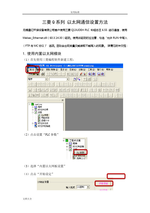
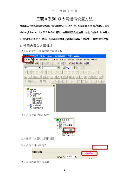
详情见附件文档:1.使用内置以太网模块(1)首先使用三菱编程软件新建工程:(2)点击设置“PLC参数”(3)选择“内置以太网板设置”(4)点击“开始设定”(5)设定内置以太网参数现象。
注意本站号:当打开时是10进制,这里必须把10进制转化成16进制,以方便组态王中使用。
填写PLC 端口号选取MC 协议2.使用外置以太网模块(1)第一个步骤同使用内置以太网模块,本例以外置以太网模块QJ17E71-100为例;(2)设置“网络参数”(3)点击“MELSECNET/以太网”(4)配置外置以太网模块可按照实际情况选择上图中的“网络类型”,“起始I/O号”,“网络号”,“组号”,“站号”,并选择对应“模式”。
(5)点击“操作设置”(6)点击“初始设置”红色框选中的选项请填写较小的数值(7)点击“打开设置”上图是选择TCP通讯协议时的情况,图中铅笔圈定的两个地方要注意,第一处一定要选“有顺序”否则会引起通讯失败,第二处一定要选“确认”,这样才能与上一图中的设置相对应,否则会导致通讯恢复需要很长时间。
当选择TCP通讯协议时最后一位一定要设为1,因为1代表TCP通信协议选择UDP通讯协议时三处红色框之处都要注意,第一处同样要选确认,理由同上,第二处和第三处没有确定的值,一般建议最好使用700以后的端口。
这里要强调的是当我们选择设备时,设置设备地址时地址中的端口值要与此图一致,如下图(8)点击传输设置以太网板以太网模块(9)选择“以太网板”此处要在注意协议的选择,如果不能和地址中的最后一项相对应(0代表UDP通讯,1代表TCP通讯)则会导致通讯失败。
三菱q系列带网口通讯plc

三菱q系列带网口通讯plc 现如今,随着工业自动化的发展,PLC(可编程逻辑控制器)成为了工业控制领域中不可或缺的一部分。
而在众多PLC品牌中,三菱(Mitsubishi)的Q系列PLC无疑是备受推崇的一款产品。
这款PLC以其可靠性、稳定性和通信能力在行业中独树一帜,越来越多的企业在各个领域中选择使用它。
Q系列PLC是三菱公司推出的一款高性能PLC产品系列,它集成了强大的通信功能,其中带网口通讯的Q系列PLC受到了广大用户的青睐。
网口通信技术使得PLC可以与其他设备快速而稳定地进行数据交换,实现了设备之间的联网控制。
在工业自动化领域中,这种能力非常关键,能够极大地提高生产效率和降低生产成本。
首先,带网口通讯的Q系列PLC具有非常强大且灵活的通信能力。
通过网口,PLC可以与PC、触摸屏、工控机等设备进行通信,实现数据的实时监控和控制。
无需额外的转换设备,简单的网络连接就能实现设备之间的高效通讯,避免了繁琐的布线过程和不必要的设备成本。
这种灵活性使得用户能够根据实际需求进行网络布置和设备连接,极大地方便了工程师的工作。
其次,带网口通讯的Q系列PLC还具有高速和稳定的数据传输能力。
通过优化网口通信协议,三菱公司确保了PLC与其他设备之间的数据传输速度和稳定性。
即使在复杂的工业环境下,也可以保证数据的可靠传输。
这对于控制系统的稳定性和实时性非常重要,特别是在高要求的生产线上,确保生产数据的准确性和及时性。
同时,带网口通讯的Q系列PLC还支持多种通信协议,如Modbus TCP、Ethernet/IP等。
这些通信协议在工业自动化领域得到了广泛应用,可以实现PLC与其他不同品牌设备的互联互通。
这就意味着用户可以使用Q系列PLC搭建开放式的自动化系统,与市场上的其他设备进行无缝对接,提高设备的兼容性和可扩展性。
另外,带网口通讯的Q系列PLC还提供了丰富的编程接口,便于工程师进行编程和网络配置。
三菱公司为Q系列PLC提供了强大的开发环境和编程软件,如GX Works2,用于编写PLC程序和进行网络配置。
三菱Q系列 以太网通信设置方法(内置以太网和外置以太网模块).doc
三菱Q系列以太网通信设置方法无锡星亿环保设备有限公司客户使用三菱Q13UDEH PLC 和组态王6.55 进行通信,使用Melsec_Ethernet.dll(60.3.14.30)驱动。
使用该驱动时应注意,勾选“允许RUN中写入(FTP与MC协议)”选项。
否则会出现变量只能读取不能写入的现象。
详情见附件文档:1.使用内置以太网模块(1)首先使用三菱编程软件新建工程:(2)点击设置“PLC参数”(3)选择“内置以太网板设置”(4)点击“开始设定”(5)设定内置以太网参数*如果选用TCP 协议则打开方式务必选取“MC 协议”如果需要多上位访问可以添加多个MC 协议,添加多个端口号。
现象。
注意本站号:当打开时是10进制,这里必须把10进制转化成16进制,以方便组态王中使用。
填写PLC 端口号选取MC 协议2.使用外置以太网模块(1)第一个步骤同使用内置以太网模块,本例以外置以太网模块QJ17E71-100为例;(2)设置“网络参数”(3)点击“MELSECNET/以太网”(4)配置外置以太网模块可按照实际情况选择上图中的“网络类型”,“起始I/O号”,“网络号”,“组号”,“站号”,并选择对应“模式”。
(5)点击“操作设置”注意一定要选取红色框中的选项,否则会造成设备初始化失败(6)点击“初始设置”红色框选中的选项请填写较小的数值(7)点击“打开设置”上图是选择TCP通讯协议时的情况,图中铅笔圈定的两个地方要注意,第一处一定要选“有顺序”否则会引起通讯失败,第二处一定要选“确认”,这样才能与上一图中的设置相对应,否则会导致通讯恢复需要很长时间。
当选择TCP通讯协议时最后一位一定要设为1,因为1代表TCP通信协议选择UDP通讯协议时三处红色框之处都要注意,第一处同样要选确认,理由同上,第二处和第三处没有确定的值,一般建议最好使用700以后的端口。
这里要强调的是当我们选择设备时,设置设备地址时地址中的端口值要与此图一致,如下图(8)点击传输设置(9)选择“以太网板”此处要在注意协议的选择,如果不能和地址中的最后一项相对应(0代表UDP通讯,1代表TCP通讯)则会导致通讯失败。
三菱Q03UDV内置以太网口和拧紧轴驱动器实现Modbus-TCP以太网通信

三菱Q03UDV内置以太网口和拧紧轴驱动器实现Modbus-TCP以太网通信三菱Q03UDV内置以太网口和拧紧轴驱动器实现ModbusTCP以太网通信一、系统概述拧紧轴由提供动力源的伺服电机、提供输出扭矩的减速机和用以检测扭矩之传感器组成,另外还需要外接控制器,用以控制、显示。
其原理是利用伺服电机做为动力单元,连接减速机构,增大输出力矩,连接扭矩传感器用以检测力矩。
扭矩传感器和伺服电机组成闭环控制,就可以精确的控制输出力矩等参数。
本文所介绍之拧紧轴驱动器支持ModbusTCP以太网协议,我们使用三菱Q03UDV系列PLC内置以太网通信协议支持功能和该拧紧轴驱动器实现ModbusTCP以太网通信,三菱Q03UDV系列PLC可对拧紧轴目标扭矩进行读、写操作。
二、通信连接1、三菱Q03UDV系列PLC内置以太网口通过网线连接至交换机LAN接口;2、拧紧轴驱动器网口通过网线连接至交换机LAN接口。
三、三菱Q03UDV系列PLC内置以太网口通信参数1、通信协议:ModbusTCPClient2、IP地址:192.168.1.1203、端口号:4096参数设置如下所示:端口中有关服务器通信参数通过编程实现,详情见PLC编程。
四、拧紧轴驱动器网口通信参数1、通信协议:ModbusTCPServer2、IP地址:192.168.1.1023、端口号:502其Modbus通信地址表如下所示,其中5008即为目标扭矩寄存器地址,为32位浮点数。
五、三菱Q03UDV系列PLC编程详解1、三菱Q03UDV系列PLC使用通信协议支持功能实现ModbusTCP客户端编程,协议包设置如下所示,即就是实现Modbus之03和16功能码,可对拧紧轴目标实现读和写操作上述03功能码数据包(协议号为1)详细设置如下所示:发送:接收:错误返回,参考通信协议的配置文件即可。
上述16功能码数据包(协议号为2)详细设置如下所示:发送:接收:错误返回,参考通信协议的配置文件即可。
Q系列以太网接口模块用户手册(Web功能)
*手册编号在封底的左下角
修订版
英语手册版本 SH-080180-B
本手册未被授予工业知识产权或其他任何类型的权利 亦未被授予任何专利许可证 三菱电机株式会社对 使用本手册中的内容造成的工业知识产权问题不承担责任
2001 三菱电机株式会社
A-3
A-3
导言
感谢您购买 MELSEC-Q 系列 PLC 使用设备前 请认真阅读本手册 以对您购买的 Q 系列 PLC 的功能和性能有清晰的认识 从而确保正确地使 用
4.3 样例屏幕的解释....................................................................................................................................... 4- 2
2 系统配置
2.1 适用系统 2.2 网络配置需要的软元件 2.3 当使用 QCPU 的远程口令功能时 2.4 当在远程 I/O 站处使用以太网模块时 2.5 当把多 PLC 系统中的以太网模块用于几个 QCPU
功能版本 B 时 2.6 当使用带 Q00J/Q00/ Q01CPU 的以太网模块时 2.7 检查功能版本和系列号
目录 本手册
安全注意事项..................................................................................................................................................A- 1 修订.................................................................................................................................................................A- 3 目录.................................................................................................................................................................A- 4 关于本手册 .....................................................................................................................................................A- 8 手册的使用 .....................................................................................................................................................A- 9 关于总称和缩写 ..............................................................................................................................................A-10
Mitsubishi PLC QJ71E71-100 Ethernet Interface Modu
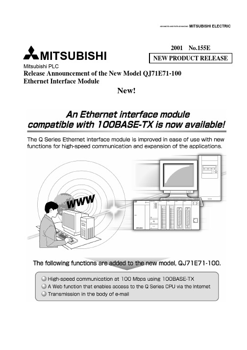
2001 No.155ENEW PRODUCT RELEASEMitsubishi PLCRelease Announcement of the New Model QJ71E71-100 Ethernet Interface ModuleNew!ADVANCED AND EVER ADVANCINGMITSUBISHI ELECTRICMITSUBISHI[New Features](1) High-speed communication at 100 Mbps using 100BASE-TXThe 100 Mbps hub (such as a switching hub) can reduce the load on the Ethernet line, improving the response performance between the QJ71E71-100 and the hub.QJ71E71-100 module responses one and half times faster than QJ71E71 and QJ71E71-B2 when Network communicates with the fixed buffers.(2) Access to the Q Series CPU via Internet using WEB function! In order to maintain and monitor remote PLC equipment via the Internet, the system administrator can collect/update PLC data or control Q Series CPU status using general Web browsers. (The clients do not need special software such as GX Developer.)! The user can easily create programs (ASP files) to access the Q Series CPU or design display forms for Web browsers (HTML files) to show the results of access to the Q Series CPU. (ASP: Active Server Pages; HTML: HyperText Markup Language)RouterQJ71E71-100Internet(Regular public network)Web browser (*1)InternetService Provider (ISP)InternetService Provider (ISP)FirewallCommunication librarySample screen (HTML files)User-created display forms (HTML files)ASP files for accessing PLCExecutes the procedure requested by the Web server and returns the resultPLC CPU dataHTTPScreen data, PLC CPU dataWeb server (*1)HTTP(Client)Note) Communication between the QJ71E71-100 and a Webserver or between a Web server and a browser is performed using HTTP (HyperText Transfer Protocol).HTTP enables the communication through proxy servers and fire walls.Q J 71E 71*1 The following table shows the specifications of web servers and browsers required for Web function. (The operations have been confirmed by Mitsubishi.)(a) Web Server (Computer on which the Web server software operates)Web server operating environmentApplicable Web server software Compatible basic software (OS) MicrosoftR Windows R2000 Server Operating SystemInternet Information Server 5.0 Microsoft RWindows R2000 Professional Operating System Internet Information Server 4.0Microsoft R Windows NT R Server 4.0 Operating SystemMicrosoft R Windows NT RWorkstation 4.0 Operating System Personal Web Server 4.0MicrosoftRWindows R98 Operating System* It is necessary to setup communication libraries, HTML file display forms and ASP files for access to the PLC in the Web server before using the Web function.* Please contact your local agency or sales company, for the purchase of communication library required for access to QJ71E71-100 module and samples (HTML file, ASP file) to confirm the functions to access to a PLC.(b) Required Web Browser! Internet Explorer 4.0 or later (Microsoft R)! Netscape RCommunicator 4.05 or later (Netscape R)(3) E-mail transmission! The user can notify the system maintenance personnel of mechanical trouble through mobile phones, so that they can take prompt actions on the trouble. In addition, the user can exchange the information on device settings and the operation of the Q Series CPU or mechanical problems as e-mail data or attached files with PCs.! Q Series CPU exchanges e-mail with target devices using special instructions (MSEND and MRECV). (Example) Sending message in e-mail data by an MSEND instructionSpecify the number of words in the subject string.Store setting values for the MSEND instruction in D20 and beyond Specify the subject string.Specify the body string.Send e-mail.! “Automatic notification function” allows QJ71E71-100 module to monitor the Q Series CPU according to CPU parameter only and to notify the monitoring result as e-mail data or attached file when the notification condition realizes(4) Connecting multiple MELSOFT products (GX Developer, GT SoftGOT),GOT! QJ71E71 module performs simultaneous PLC access to each device, taking advantage of long-distance and high-speed communication (Ethernet communication), when you connect the module with multiple MELSOFT products and GOTs via Ethernet (direct connection).! Multiple program developers can debug the Q Series CPU using GX Developers (a maximum of 17 units). (Debugging can also be performed through a reliable TCP/IP communication.)EthernetGX DeveloperGX DeveloperGX DeveloperMonitoring the deviceMonitoring program executionTesting the deviceQ J 71E 71[Function](1) Basic Functions of Ethernet Interface Modules (TCP/IP Communication and UDP/IP Communication)Function Description QJ71E71-100QJ71E71QJ71E71-B2QnA compatible 3E frame Communication using the MC protocolA compatible 1E frame Reads/writes PLC CPU data from/to an external device. ""Procedure exist Communication using fixed buffersNo ProcedureReads/writes any data between PLC CPU and an external device using fixed buffer of the Ethernet modules." " Communication using random access buffersReads/writes data from/to the random access buffers of the Ethernet modules of multiple external devices. ""Sends/receives data using e-mail.! Sends/receives data using a sequence program. ! Sends information using the automatic notification function." " Sends an attached file in CSV format. " " Sending/receiving by e-mailSends e-mail body." × Communication using data link instructions Reads/writes PLC CPU data of other stations via the Ethernet using data link instructions." " File transfer (FTP Server Function) Reads/writes files using the FTP command on external devices." " Communication using Web functionReads/writes PLC CPU data via the Internet using commercially available Web browsers."×(2) Additional Functions of Ethernet Interface ModulesFunction Description QJ71E71-100QJ71E71QJ71E71-B2MELSECNET/H, MELSECNET/10relay communicationIn a network system on which the Ethernet, MELSECNET/H andMELSECNET/10 exist or in a network system that relays multipleEthernet nets, data is communicated via several such networks." " Router relay communication (Router relay function) Communicates data via routers and gateways. (Ethernet interface module does not function as a router.) " " External device existence confirmation Checks whether or not the external device operates normally after communication has been established (open processing)." " Paring open communicationReceiving connection and transmitting connection are opened as asingle pair. (For fixed buffer communication.)" " Communication using automaticopen UDP portCommunication is enabled after starting up the station with theEthernet interface module. (Opening and closing by a sequenceprogram is unnecessary.)" " Prohibits remote users from performing illegal accesses to QCPU" " Communication using the MC protocol" " Communication using GX Developer" " Communication using the file transfer function" " Compatibility with QCPU remotepassword functionRemote password unlocking/locking Communication using the Web function" × Simultaneous broadcast Sends/receives data to/from all external devices in the same Ethernetas the Ethernet interface module, through the communication byUDP/IP.""(3) Status Check of the Ethernet Interface ModuleFunction Description QJ71E71-100QJ71E71QJ71E71-B2Self refrain test Checks the Ethernet interface module sending/receiving function and line connection status." " Hardware testTests the RAM and ROM of the Ethernet interface module." " Communication error storageStores the error information (error log), including message subheader, IP addresses of the external device, etc., for a maximum of 16 pairs in the buffer memory area, when a data communication error occurs.""(4) OthersDescription QJ71E71-100QJ71E71QJ71E71-B2Initial processingPerforms initial processing by setting GX Developer parameters. " " Performs open processing using sequence programs." " Open processingPerforms open processing by setting GX Developer parameters. " " Installs an Ethernet interface module to multiple PLC system." " Communication using the MC protocol" " Communication using GX Developer" " Compatibility with multiple PLCsystemAccessing non control PLC Communication using the file transferfunction" × Install an Ethernet interface module to MELSECNET/H remote I/O station." " Set parameters in the GX Developer to use Ethernet interface module functions. " " Access QCPU through the Ethernet interface module (TCP/IP or UDP/IP)." " Monitor various statuses of the Ethernet interface module." " Diagnosis based on PING test" " Through the Ethernet board Diagnosis based on loop back test" " Diagnosis based on PING test" " Compatibility with the GXDeveloper Ethernet diagnosticfunction (GX Developer Version 6or later) Through the CPUDiagnosis based on loop back test" " Communication using the IEEE802.3 frame" × Connection of MELSOFT products (such as GX Developer)" "Simultaneous connection with multiple MELSOFT products usingTCP/IP communication.""" : Available × : Not availablePlease refer to the Q corresponding Ethernet Interface module User’s Manual (SH-080009-C), for the function versions and serial numbers of the products (CPU module and GX Developer) related with the above functions.SpecificationQJ71E71-100 QJ71E71 QJ71E71-B2Item100BASE-TX 10BASE-T 10BASE-T 10BASE5 10BASE2Data transmission rate 100Mbps 10MbpsTransmission method Base band Maximum node-to-nodedistance- 2500m (8203ft.) 925m (3035ft.)Maximum segment length 100m (323ft.) (between hub and node) 500m (1641ft.) 185m (607ft.)Maximum number of nodes per connection Cascade connection, maximum 2 Cascade connection,maximum 4 100 units/ segment 30 units/ segmentTransmission Specifications Minimum node interval - 2.5m (8.2ft.) 0.5m (1.6ft.) Number of simultaneouslyopen connections allowed16 connections (Connections usable by the sequence program)Fixed buffer 1k words × 16Random access buffer 6k words × 1Attached file 6k words × 1 Send/receivedata storagememoryE-mail (*1) Body (main text) 960 words × 1 -Number of I/O points occupied 32 points (I/O assignment: Intelli.) 5V DC current consumption 0.50A 0.70A 12V DC external supply power capacity (fortransceiver)(*2)*1 The following table outlines the specifications of the e-mail transmission and reception function.SpecificationQJ71E71-100 QJ71E71 QJ71E71-B2Item100BASE-TX 10BASE-T 10BASE-T 10BASE5 10BASE2Attached file6k words × 1DatasizeBody(main text)960 words × 1-Data transfer method Sending : Transmit either as anattached file or in the body Receiving : Receive as an attached fileSend/receive as an attached fileSubject Us-ASCII format or ISO-2022-JP (Base64) Attached file format MIME formatMIME Version 1.0Data of attached fileformatBinary data/ASCII code/CSV can be selected.File name: XXXX.bin (binary), XXXX.asc (ASCII), XXXX.csv (CSV)(CSV: Comma Separated Value)Division of attachedfileNot performed (Only 1 file can be sent/received.) Note) If any divided files are received, only the first file is received and the remaining files are discarded. Sending (encode) Subject : Base64Body : 7 bit (QJ71E71-100 only)Attached file : Base64 Receiving (decode)Subject : (not decoded) Body : (cannot be received) Attached file : Base64/7 bit/8 bit Note) Specify the encoding (Base64/7bit/8bit) of the attached file, when sending an e-mail from anexternal device to PLC side.Encryption No Compression No Transmissionspecifications Sending/ receiving dataCommunication with mail server SMTP (sending server) Port number = 25 POP3 (receiving server) Port number = 110*2 It is necessary to use a power supply that meets the specifications of the transceiver and AUI cable, considering the voltage drop(maximum 0.80V) in the module.Unit : mm (inch)28.0(1.10)R1(*1)27.4 (1.08)90 (3.54)98 (3.86)*1 The bending radius near the connector (reference value: R1) should be four times large as the cable’s external diameter or larger, fortwisted pair cable connection.[Packing List]Product NameModel Type QJ71E71-100 Ethernet Interface Module QJ71E71-100 Type QJ71E71 Ethernet Interface Module QJ71E71 Type QJ71E71-B2 Ethernet Interface ModuleQJ71E71-B2[Manual]Manual nameManual shipping form IB/SH number Model code Ethernet Interface module User’s Manual (Hardware)Enclosed with the productIB-0800009-D or later 13JQ35 Q Corresponding Ethernet Interface Module User’s Manual (Basic)Sold separately SH-080009-C or later 13JL88 Q Corresponding Ethernet Interface Module User’s Manual (Application) Sold separately SH-080010-C or later13JL89 Q Corresponding Ethernet Interface Module User’s Manual (Web function)Sold separately SH-080180 13JR40 Q Corresponding MELSEC Communication Protocol Reference ManualSold separatelySH-080008-C or later13JF89Microsoft Windows, and Microsoft Windows NT are registered trademarks of Microsoft Corporation, USA in the United States and other countries.Netscape is a registered trademark of Netscape Communications Corporation in the United States and other countries.Ethernet is a registered trademark of Xerox, Co. Ltd. of USA.Other company names and products mentioned in this new-product bulletin are the trademarks or registered trademarks of their respective owners.Country/Region Salesoffice Tel/FaxU.S.A Mitsubishi Electric Automation Inc.500 Corporate Woods Parkway Vernon Hills, IL 60061 Tel : 1-847-478-2100 Fax : 1-847-478-0328Brazil MELCO-TEC Rep. Com.e Assessoria Tecnica Ltda.Av. Rio Branco, 123-15 ,and S/1507, Rio de Janeiro, RJ CEP 20040-005, Brazil Tel : 55-21-221-8343 Fax : 55-21-221-9388Germany Mitsubishi Electric Europe B.V. German BranchGothaer Strasse 8 D-40880 Ratingen, GERMANY Tel : 49-2102-486-0 Fax : 49-2102-486-717U.K Mitsubishi Electric Europe B.V. UK BranchTravellers Lane, Hatfield, Herts., AL10 8XB,UK Tel : 44-1707-276100 Fax : 44-1707-278695Italy Mitsubishi Electric Europe B.V. Italian BranchCentro Dir. Colleoni, Pal. Perseo - Ingr.2Via Paracelso 12, 20041 Agrate B., Milano, Italy Tel : 39-039-6053301 Fax : 39-039-6053312Spain Mitsubishi Electric Europe B.V. Spanish BranchCarretera de Rubi 76-8008190 - Sant Cugat del Valles, Barcelona, Spain Tel : 34-935-653135 Fax : 34-935-891579South Africa MSA Manufacturing (Pty) Ltd.P O Box 39733 Bramley 201 8 Johannesburg, South Africa Tel : 27-11-444-8080 Fax : 27-11-444-8304Hong Kong Ryoden International Ltd.10th Floor, Manulife Tower, 169 Electric Road, North Point, HongKong Tel : 852-2887-8870 Fax : 852-2887-7984China Ryoden International Shanghai Ltd.3F Block5 Building Automation Instrumentation Plaza 103 Cao Bao Rd. Shanghai200233 China Tel : 86-21-6475-3228 Fax : 86-21-6484-6996Taiwan Setsuyo Enterprise Co., Ltd.6F., No.105 Wu-Kung 3rd.RD, Wu-Ku Hsiang, Taipei Hsine, Taiwan R.O.C. Tel : 886-2-2299-2499 Fax : 886-2-2299-2509Korea HAN NEUNG TECHNO CO.,LTD.1F Dong Seo Game Channel Bldg., 660-11,Deungchon-dong Kangsec-ku,Seoul, Korea Tel : 82-2-3668-6567 Fax : 82-2-3664-8335Singapore Mitsubishi Electric Asia Pte, Ltd.307 ALEXANDRA ROAD #05-01/02,MITSUBISHI ELECTRIC BUILDING SINGAPORE 159943 Tel : 65-473-2480 Fax : 65-476-7439Thailand F. A. Tech Co.,Ltd.898/28,29,30 S.V.CITY BUILDING,OFFICE TOWER 2,FLOOR17-18 RAMA 3 ROAD,BANGKPONGPANG,YANNAWA,BANGKOK 10120 Tel : 66-2-682-6522 Fax : 66-2-682-6020Indonesia P.T.Autoteknindo SUMBER MAKMURJL. MUARA KARANG SELATAN BLOK A UTARA NO.1 KAV.NO.11 KAWASAN INDUSTRI/ PERGUDANGAN JAKARTA - UTARA 14440 Tel : 62-21-663-0833 Fax : 62-21-663-0832India Messung Systems Put,Ltd.Electronic Sadan NO:111 Unit No15, M.I.D.C BHOSARI,PUNE-411026 Tel : 91-20-7128927 Fax : 91-20-7128108Australia Mitsubishi Electric Australia Pty. Ltd.348 Victoria Road, PostalBag, No 2, Rydalmere, N.S.W 2116, Australia Tel : 61-2-9684-7777 Fax : 61-2-9684-7245HEAD OFFICE:MITSUBISHI DENKI BLDG MARUNOUCHI TOKYO 100-8310 TELEX:J24532 CABLE MELCO TOKYO01 (MEE) Specifications subject to change without notice.。
三菱Q系列以太网通信设置说明文档

以太网板
(9)选择“以太网板”
此处要在注意协议的选择,如果不能和地址中的最后一项相对应(0 代表 UDP 通 讯,1 代表 TCP 通讯)则会导致通讯失败。 (10)点击“以太网模块”
9
三菱 Q 系列 以太网通信设置
工业自动化-花落忆无声
说明文档
IP 地址不要填错,否则会导致通讯。失败然后将这些参数设置写入 PLC,确 认写入 PLC 后,便可进行在线监视。
如:192.168.1.8:800:401:3:1,组态王中的定义与 PLC 软件中的配置对应如下
注:本机的端口号(即 ComputerPort)应设置的大一些,太低容易被其他程序占用,建议 设置到 4000 以上。
8
三菱 Q 系列 以太网通信设置
(8)点击传输设置
工业自动化-花落忆无声
说明文档
以太网模块
10
6
三菱 Q 系列 以太网通信设置
工业自动化-花落忆无声
说明文档
当选择 TCP 通讯协议时最后一位一定要设为 1,因为 1 代表 TCP 通信协议
选择 UDP 通讯协议时三处红色框之处都要注意,第一处同样要选确认,理由 同上,第二处和第三处没有确定的值,一般建议最好使用 700 以后的端口。这里 要强调的是当我们选择设备时,设置设备地址时地址中的端口值要与此图一致, 如下图
(5) 点击“操作设置”
注意一定要选取红色框中的选项,否则会造成设备初始化失败 (6)点击“初始设置”
5
三菱 Q 系列 以太网通信设置
工业自动化-花落忆无声说明源自档红色框选中的选项请填写较小的数值 (7)点击“打开设置”
上图是选择 TCP 通讯协议时的情况,图中铅笔圈定的两个地方要注意,第 一处一定要选“有顺序”否则会引起通讯失败,第二处一定要选 “确认”,这 样才能与上一图中的设置相对应,否则会导致通讯恢复需要很长时间。
- 1、下载文档前请自行甄别文档内容的完整性,平台不提供额外的编辑、内容补充、找答案等附加服务。
- 2、"仅部分预览"的文档,不可在线预览部分如存在完整性等问题,可反馈申请退款(可完整预览的文档不适用该条件!)。
- 3、如文档侵犯您的权益,请联系客服反馈,我们会尽快为您处理(人工客服工作时间:9:00-18:30)。
4.4 样例屏幕上数据通信的例子 .................................................................................................................... 4- 3
4.4.1 软元件读取/写入............................................................................................................................... 4- 5
4.4.4 代理服务器设置.............................................................................................................................. 4- 13
4.5 样例屏幕上文件的配置.......................................................................................................................... 4- 15
3 操作步骤
3- 1 至 3- 4
3.1 使用 Web 功能进行通信之前的一般步骤 ............................................................................................... 3- 1 3.2 如果获得并设置通讯库和样例屏幕......................................................................................................... 3- 2
! 危险
表示错误操作可能造成灾难性后果 引起死亡或重伤事故
! 小心
表示错误操作可能造成危险后果 引起人员轻伤 中度伤害或财产 损失
注意根据情况不同 ! 小心这一级也能引发严重后果 因此请勿必遵守以上两级对人员安全至关重要的注意事项
请妥善保管本手册 以便需要时就能够取阅 并且一定要把它发送给最终使用者
[操作注意事项]
! 小心
• 通过把个人计算机等连接到智能功能模块来对正在运行的 PLC 进行控制操作 尤其是对数据 程序和运行状态 状态控制 的修改 之前 请仔细阅读用户手册并确认绝对安全 对数据 程序和运行状态的不正确修改可能导致系统故障 损坏机器或引发事故
A-2
A-2
初版
制作日期
*手册编号
2002 年 10 月 26 日 SH(NA)–080410C–A 修订履历
目录 本手册
安全注意事项..................................................................................................................................................A- 1 修订.................................................................................................................................................................A- 3 目录.................................................................................................................................................................A- 4 关于本手册 .....................................................................................................................................................A- 8 手册的使用 .....................................................................................................................................................A- 9 关于总称和缩写 ..............................................................................................................................................A-10
• 当从外部设备进行 PLC CPU 的状态控制 远程 RUN/STOP 等 时 选择由用户提前设置的 始终等待 OPEN 参数 用操作设置中的初始化时序设置选择 如果选择 不等待
OPEN 则关闭远程 STOP 处的通讯线路 关闭后 再也不能在 PLC CPU 端重新断开通讯线 路 并且无法从外部设备起动远程 RUN
4.4.2 远程 RUN/STOP .............................................................................................................................. 4- 9
4.4.3 数据请求 ......................................................................................................................................... 4- 11
2 系统配置
2- 1 至 2- 3
2.1 系统配置 .................................................................................................................................................. 2- 1 2.2 使用 Web 功能的注意事项...................................................................................................................... 2- 3
4.3 样例屏幕的解释....................................................................................................................................... 4- 2
[设计注意事项]
! 危险
• 关于数据链接中发生通讯异常时各个站运行状态的详情 请参考各个数据链接手册 错误输出和 故障可能导致事故 否则可能因错误输出或故障而引发事故
• 为了防止外来非法电子邮件引发 PLC 系统故障 应采取正确的措施 如病毒检测 使本模块 的邮件服务器不接收非法电子邮件
• 如果需要确保 PLC 系统的安全 用户必须采取适当措施防止未经授权就通过因特网从外部设备 进行访问
• 通过把外围设备连接到 CPU 模块或把个人计算机连接到智能功能模块来控制正在运行的 PLC 修改数据 要在顺控程序中配置互锁电路 以确保整个系统的安全 另外 在正在运行的
PLC 上进行其它控制操作 修改程序和运行状态 状态控制 之前 一定要仔细阅读本手册 并且要确认绝对安全
尤其在从外围设备对远程 PLC 进行上述控制操作中 由于异常数据通讯 PLC 端的所有问题都 可能得不到及时处理 除了要在顺控程序中配置互锁电路之外 还要确定系统怎样处理对方设备 和 PLC CPU 之间的数据通讯异常性
3 规格
3.1 性能规格 3.2 通讯用的数据代码 3.3 外部设备和各个通讯功能的附加功能之间的关系 3.4 以太网模块功能列表 3.5 专用指令列表 3.6 用于以太网模块的 GX Developer 设置项目列表 3.7 输入 PLC CPU 或从 PLC CPU 输出的信号列表 3.8 缓冲存储器的应用和分配列表
4 使用样例屏幕验证 Web 功能的操作
4- 1 至 4-16
4.1 样例屏幕上可用的 Web 功能项目 .......................................................................................................... 4- 1
A-1
A-1
[设计注意事项]
! 危险
• 不要把任何数据写入智能功能模块缓冲存储器的 系统区 另外 不要输出 打开 从 PLC CPU 到智能功能模块输出信号之一的 禁用 信号 如果数据写入 系统区 或输出 禁用 信号 则 PLC 系统有发生故障的危险
! 小心
• 不要将控制线和通讯电缆捆扎到主回路或电源线上 安装时也不要使它们靠得太近 安装时它们应彼此间隔至少 100mm 3.94in. 否则会产生噪声并导致故障
1 概述
1- 1 至 1- 4
1.1 概述.......................................................................................................................................................... 1- 1