数字逻辑设计Digital Logic Design.pdf
Lecture 1 Introduction to Digital Logic Design[第1讲介绍数字逻辑设计]
![Lecture 1 Introduction to Digital Logic Design[第1讲介绍数字逻辑设计]](https://img.taocdn.com/s3/m/0798f1fdad51f01dc381f126.png)
• Teaching Assistant
– Peng Kang – Office: M314 Tech – EMAIL: pengkang2011@
• Web Page: EECS 303 Lecture 1 /~haizhou/303/
– Chapter 1 – Chapter 2
EECS 303 Lecture 1
2
Class Administration
• Lectures twice a week, Tuesday-Thursday 3:304:50PM • Instructor:
– – – – Hai Zhou Office: L461 Tech EMAIL: haizhou@ PHONE: 491-4155
Implementation
Assemble primitives into more complex building blocks Composition via wiring Choose among alternatives to improve the design Debug Faulty systems: design flaws, composition flaws, component flaws Design to make debugging easier Hypothesis formation and troubleshooting skills
EECS 303 Lecture 1
7
The Process of Design
Design Implementation Debug
Design Initial concept: what is the function performed by the object? Constraints: How fast? How much area? How much cost? Refine abstract functional blocks into more concrete realizations
姜书艳 数字逻辑设计及应用 1
课堂录像
学生听课时应精神饱满, 适时做笔记,不要趴在桌 子上或斜坐在座位上。
桌面保持适当的整洁。 课堂上应与老师进行必要
的互动。
21
Digital Logic Design and Application (数字逻辑设计及应用)
课程简介
“数字逻辑设计及应用”课程历来是我校的重要专业基 础课程之一,是研究数字系统设计的入门课程。
Digital Logic Design and Application (数字逻辑设计及应用)
习题 每次课 2—4题(基本采用教材习题); 每章结束上交,批改后将进行针对性讲解,并
给出参考解答; 每课一题
每次内容讲解的课上布置,自备一页纸完成, 要求当堂完成上交;
课程设计 综合性考查,组合电路和时序电路各一次,要
5
普林斯顿大学的本科培养目标:
具有清楚的思维、表达和写作能力 具有以批评的方式系统推理的能力
具有形成概念和解决问题的能力 具有独立思考的能力
具有敢于创新及独立工作的能力 具有与他人合作的能力
6
普林斯顿大学的本科培养目标:
具有判断什么意味着彻底理解某种 东西的能力
具有辨识重要的东西与琐碎的东西、 持久的东西与短暂的东西的能力 熟悉不同的思维方式 具有某领域知识的深度
反馈da转换电子系统所包含的知识点及其相互关系脉冲的产生和整形组合电路时序电路单片机30数字逻辑数字逻辑设计设计数字逻辑数字逻辑设计设计微机原理及接口技术微机原理及接口技术数字系统设计数字系统设计vlsi设计vlsi设计edaeda设计设计31课程的先进性先进性主要体现在元器件和方法1947年晶体管1958年集成电路69年大规模集成电路75年超大规模集成电路20世纪80年代pld迅速发展按10倍6年集成度发展20世纪90年代模拟可编程器件20世纪90年代提出soc的概念palgalepldcpldisppldfpga21世纪初产生psocpsoc单片机sopc32内核可编程数字模块阵列可编程模拟模块阵列系统总线8位微处理器系统时钟源程序和数据存储器乘法累加压检测电路升压泵内部参考电压模拟多路开关大电流输出驱动
数字系统设计.pdf

PLD设计——CPLD与FPGA的区别
规模
CPLD规模一般比FPGA小,最多512个宏单元;FPGA则可以实现单片 1000万门。
速度
CPLD的速度可以比FPGA更高,其连线的延时固定,更适合做高速的应 用;FPGA的互连线为多段,延时不确定。
逻辑特点 CPLD适合做逻辑密集型的应用,FPGA适合做数据密集型的应用。 编程方式
ALTERA
XILINX
FPGA/CPLD生产商
ispLSI系列:1K、2K、3K、5K、8K ispLSI1016 、ispLSI2032、 ispLSI1032E、ispLSI3256A MACH系列 ispPAC系列:
LATTICE VANTIS (AMD)
CPLD
其他PLD公司: ACTEL公司: ACT1/2/3、40MX ATMEL公司:ATF1500AS系列、40MX CYPRESS公司 QUIKLOGIC公司
数字系统分类
数字系统本身实现的方法很多,一般来说,可以分为 以下几种方法: PLD(可编程逻辑器件) MCU(单片机) DSP(数字信号处理器) Embedded System(嵌入式系统) 以上几种设计方法的应用场合不同,设计方法也大 不相同,应该根据不同的应用场合、成本和设计的 难度来决定使用合适的设计方法。
SO MUCH IC!
FPGA CPLD
PLD设计——PLD设计的流程
设计输入
原理图 硬件设计语言
功能仿真
验证逻辑是否正确
综合
将原理图或者硬件描述语言翻译为网表。
时序仿真
加载器件延时文件后的仿真,验证在器 件上实现后的实际性能。
不同数字系统的应用场合(4)
Embedded System(嵌入式系统)
数字逻辑与部件设计-硬件描述语言+HDL

• 综合 Synthesis
– High Level Synthesis
– RTL Synthesis
– Logic Synthesis
• 布图 Layout
网表netlist
– 布局 (Placement)
– 布线 (Routing)
• 版图参数提取和验证
如导线电阻,导线间寄生电容
• 测试和诊断
4
begin
A1 = 1'b0; B1 = 1'b0; C1 = 1'b0; //1位二进制0
#100 A1 = 1'b1; B1 = 1'b1; C1 = 1'b1;
end
initial #200 $finish; //200ns结束
endmodule
不知其值是多少
16
Vivado2015中模拟结果
|
或
||
逻辑或
===
全等
^
异或
!==
不全等
^~
同或
AND优先级比OR高
• 缩位运算符:对单个操作数进行运算,最后返回一位数。
运算过程:首先将操作数的第一位和第二位进行与、或、非运算;
然后再将运算结果和第三位进行与、或、非运算;以此类推直至
最后一位。例子见下页...
• 拼接运算符:{s1, s2, …, sn}
2
g6
endmodule
g5
3
13
练习2. 画出下面的电路图
module Circuit_2 (A, B, C, D, F);
input A, B, C, D;
output F;
wire w, x, y, z, a, d;
数字逻辑设计实验室指导书说明书

LAB BROCHUREDigital Logic Design Lab DEPARTMENT OF ELECTRICAL ENGINEERINGCONTENTS...................................................................................................................... Lab Venue 3............................................................................................. Lab Objectives & Courses 3 Lab Description & Experiments 4....................................................................................................................................................................................... Hardware Experiments 5 ....................................................................................................... Verilog Experiments 6 Lab Resources 7...............................................................................................................DLD Lab Venue: Computer Interfacing Lab First Floor, Electrical DepartmentLab VenueThe Digital Logic Design Lab (DLD Lab) is one of the most important and well equipped lab of the Department of Electrical Engineering at University of Engineering and Technology, Lahore. This lab is conducted at the Computer Interfacing Lab situated at the first floor of the Electrical Engineering Department.Scope of the LabThe DLD Lab is for undergraduate coursework related to the course EE131. It is one of the core modules of B. Sc. Electrical Engineering therefore the lab has a significant importance in the department.Related CoursesThis lab is designed such that thestudents get a hands on familiaritywith the concepts they come acrossin the course EE131 that is the DigitalSystems course. This is anundergraduate course which dealswith the basics of digital systemsdesign and is a core module of theB. Sc. Electrical Engineeringcoursework as it provides theprerequisites for advance courses indigital electronics. Because of thesignificance of this course the DLDLab has been carefully designed tomeet the course requirement.Brief Overview of the LabThe Lab is well equipped withboth hardware and software facilitiesrequired by the students to performthe necessary experiments designedfor this lab. Details of the labequipment has been discussed in aproceeding section.Experiments are designed insuch a way that the students becomewell aware of the concepts they learnin the theory sessions. A list ofexperiments that are conducted inthis lab has also been mentioned in aproceeding section.Experiments are related to bothdigital hardware and VerilogProgramming.Objectives & CoursesLab Description & ExperimentsLab DescriptionThe Experiments in the Lab have been divided into two major portions:•Hardware Labs•Hardware Description Language (Verilog) LabsHardware Labs have been designed to familiarize students with the Combinational Digital Logic Design and Sequential Digital Logic Design through the implementation of Digital Logic Circuits using ICs of basic logic gates and some simple digital logic circuits.HDL (Verilog) Labs havebeen designed tofamiliarize students with theHDL based Digital DesignFlow. These labs introducestudents with differentlevels of coding available inVerilog i.e. Gate level,Dataflow level andBehavioral level. Xilinx ISE7.1 tools have been used inthese labs. Finally, theskills learnt in the HDLlabs are employed toimplement some digitallogic circuits on Spartan-3FPGA, using Xilinx StarterKit Development Board.Expected OutcomesWith the help of the twothreads of the labmentioned above, studentswill have clearunderstanding of all thethree paradigms ofimplementation of digitallogic circuits:•Implementation usingICs for basic logic gatesand simple circuits•Implementationthrough the Developmentof Dedicated IC(ASIC)•Implementationthrough ReconfigurableLogic (i.e. FPGA)This makes studentsadept in basic conceptsinvolved in digital logicdesign. The lab contributesa lot to the basic learning ofdigital systems.This shows theindispensability of theDLD Lab.List of ExperimentsList of experiments isgiven on page 5 and 6. Asmentioned before the labhas two major portionstherefore there are two listsof experiments one relatedto the hardware labs andthe other related to thehardware descriptionlanguage (verilog) labs. Allthese experiments aremandatory and each lab isfollowed by speciallydesigned assignments.A Lab DemonstrationA Digital Chip (inside view)TITLE TOPICS1To Verify the Behavior of Logic Gates using Truth Table and Familiarization with Digital Integrated Circuits Basic Logic Gates, Truth Table, Integrated Circuits2Implementation of Boolean Function using Logic Gates and Introduction to Hierarchical Design of Digital Logic Circuits Boolean Functions,Boolean Algebra,Hierarchical Design of Digital Logic Circuits3Familiarization with the Different Portions of the Datasheet fora Digital IC and Using the Datasheet to Gather RelevantInformation to Utilize the IC as a Component in another DigitalLogic Circuit Datasheet of a Digital Logic IC, Hierarchical Design of Digital Logic Circuits4Implementation of 8 bit Binary Comparator using 4 bit Binary Comparators Binary Comparator,Hierarchical Design of Digital Logic Circuits5Implementation of 4bit into 3bit Binary Multiplier using 4bit Binary Adders Binary Multiplication,Hierarchical Design of Digital Logic Circuits6Implementation of BCD Adder using 4bit Binary Adders, 4 to 7 Segment Decoder and 2Digit 7 Segment Display BCD addition,Hierarchical Design of Digital Logic Circuits7Implementing a Full Adder using(a) Decoder(b) Multiplexer Implementation of Boolean function using Decoder,Implementation of Boolean function using Multiplexer8Flip Flops Different Types of Flip Flops9To study the fundamentals of basic counters and to construct various types of counters CountersHardware ExperimentsTITLE TOPICS1Introduction to HDL based Digital Design Methodology HDL based Digital Design Flow usingVerilog,Introduction to Outsourcing Business Model2Introduction to Basic Syntax of Verilog and Gate level Modelingthrough implementation of half adder at gate level and itssimulation using Xilinx ISE tools Basic Concepts of Verilog, Modules and Ports, Gatelevel coding in Verilog,3Introduction to the concepts of Instantiation and HierarchicalDesign in Verilog through the implementation of full adderusing the previously designed half adder modulesHierarchical Design in Verilog4Introduction to the Concept of Vectors and Introduction to Dataflow modeling through implementation of half adder andfull adder at dataflow level Vectors in Verilog,Dataflow level coding in Verilog5Consolidation of the concepts of Dataflow level modeling and Introduction to the concept of Synthesis by the CAD tool Dataflow level coding in Verilog, Logic Synthesis6Introduction to Behavioral modeling through implementation ofhalf adder and full adder at behavioral level.Behavioral level coding in Verilog7Introduction to if else statement and case statement inBehavioral modeling through implementation of Multiplexerif else and case statements in Verilog8Introduction to the Concepts of Sequential Circuit anda TestBench module (Stimulus Block)Sequential circuits in Verilog, Concept of Testbench module in Verilog9Behavioral Level Coding of Basic Sequential Circuits andConsolidation of the concepts of TestBench module (StimulusBlock)Sequential circuits in Verilog10Introduction to Field Programmable Gate Array(FPGA) and Steps involved in its Programming Need for Reconfigurable Logic, Xilinx ISE Tools for Programming the Xilinx FPGAsVerilog ExperimentsLab ResourcesHardware ResourcesThe lab is fully equipped with all the hardware required to conduct the above mentioned experiments. The hardware resources of the lab are:•Pentium-IV PCs (with MS WinXp OS)•Hardware trainers for logic circuit design and analysis•Electronic Chips of all digital gates•Spartan-III FPGA board kits•Power SuppliesThese resources allowthe students to have ahands on experience ofbasic digital logic designconcepts. This activitygreatly leverages what thestudents learn in the theorysessions.Software ResourcesThe lab also consists ofthe software resourcesrequired by the studentsnamely:•Veriwell•ModelSim•Xilinx IDE•MatlabSoftware resources areequally important ashardware resources are.These software resourcesare sufficient for thestudents to performexperiments. Thesesoftwares provide thestudents with thenecessary platform to workon HDL that is the Verilog.These softwares are alsorequired to work with thesophisticated hardwareslike Spartan-III FPGAboards.The lab has all theresources whether relatedto hardware or software sothat the students becomeadept in the basic field ofdigital electronics.Students areencouraged to use the labresources to performactivities andexperiments which helpthem strengthen theirconcepts.Lab StaffLike other labs of thedepartment there is atrained and able staffconsisting of skilled labtechnicians that take careof the lab equipment.They also guidestudents about handlingthe lab equipment and theprecautionary measuresrequired for the studentswhile working in the lab.A Digital Circuit BoardA SimulationDIGITAL LOGIC DESIGN LAB1st Floor, Department of Electrical Engineering UNIVERSITY OF ENGINEERING & TECHNOLOGY, LAHORE-54890, PAKISTAN..pkurl:Ph: + 92 42 9029229, Fax: + 92 42 9250224Computer Interfacing Lab。
姜书艳数字逻辑设计及应用17

Two Types (逻辑电路分为两大类): Combinational Logic Circuit
(组合逻辑电路) Sequential Logic Circuit (时序逻辑电路)
3
Digital Logic Design and Application (数字逻辑设计及应用)
锁存器清0:Qn+1=0 QLn+1=1
QL 1
即使S,R无效(=0) 锁存器仍能锁定0态
a. 原态:Qn=0,QLn=1
1
新态:Qn+1=0,QLn+1=1 R
b. 原态:Qn=1,QLn=0
10
新态:Qn+1=0,QLn+1=1
Q
14
Q_L
Digital Logic Design and Application (数字逻辑设计及应用)
Metastable Behavior (亚稳态特性)
Apply a definite Pulse Width from a Stable
state to the Other.
(从一个“稳态”转换到另一个“稳态” 需加一定宽度的脉冲(足够的驱动))
—— The Basic Building Blocks of most Sequential Circuits.
(大多数时序电路的基本构件)
Flip-Flops( F/F,触发器)
只在时钟信号的有效边沿改变其输出状态
17
Digital Logic Design and Application (数字逻辑设计及应用)
数字逻辑与部件设计-组合逻辑设计
C
0
1
0
1
E
0
0
1
0
10
SOP & POS Form
• SOP – sum-of-products
O
0
0
1
1
C
0
1
0
1
E
0
0
1
0
minterm
O C
O C
O C
O C
ഥ = ()
=
ത + )
′ = (ത ҧ +
• POS – product-of-sums
O
0
0
1
1
C
Outputs determined by current values of inputs
时序逻辑 Sequential Logic
Has memory
Outputs determined by previous and current values of inputs
Rules of Combinational Composition
A
0
0
1
1
B
0
1
0
1
Y
0
1
0
1
maxterm
maxterm name
A
A
A
A
+
+
+
+
B
B
B
B
M0
M1
M2
M3
ഥ + ) = (, )
= (, ) = ( + )(
9
Boolean Equations Example
姜书艳 数字逻辑设计及应用
Equations
1 Circuits
2
4
6
3
5
Truth table
c' F = c'(h+p)
h+p
24
24
.
Converting among Representations
More common conversions
Truth table to equation (which we can then convert to circuit)
.
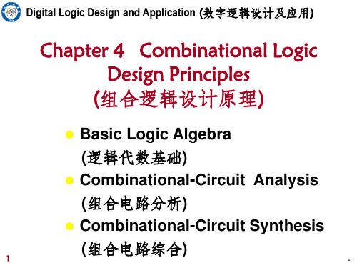
Review of 4.1 Switching Algebra (开关代数内容回顾)
4、 n-Variable Theorems (n变量定理)
Generalized Idempotency
(广义同一律)
X+X+…+X=X
Shannon’s Expansion TheF o(rX e1m,X Xs2·, X ,·X …n)· X = X
AB F
(负逻辑): F = A+B
Negative-Logic Convention
AB F
LL L
LH L
HL L
5
HH H
00 0 01 0 10 0 11 1
11 1
10 1
01 1
00 0
.
Digital Logic Design and Application (数字逻辑设计及应用)
补充:逻辑函数及其表示方法
commonly used
11
11
.
2.5
Boolean Algebra
Boolean algebra precedence, highest precedence first.
- 1、下载文档前请自行甄别文档内容的完整性,平台不提供额外的编辑、内容补充、找答案等附加服务。
- 2、"仅部分预览"的文档,不可在线预览部分如存在完整性等问题,可反馈申请退款(可完整预览的文档不适用该条件!)。
- 3、如文档侵犯您的权益,请联系客服反馈,我们会尽快为您处理(人工客服工作时间:9:00-18:30)。
数字逻辑设计——绪论
13
数字的出现
数字的出现
数字在各个古代文明中都独立的存在 数字都采用十进制数 阿拉伯数字
Digit的词义
人的手指或脚趾 指宽 阿拉伯数字符号从0到9中的任意一个 用于计算系统中的符号
数字逻辑设计——绪论
14
早期的计算用具
数字逻辑设计——绪论
11
构造计算机的装置
电子装置
处理器 存储器
机械装置
用于磁盘读写的寻道手臂
光学装置
CDROM
数字逻辑设计——绪论
12
计算的历史
计算机历史只有50年多年?
不对! 数字电子计算机的历史只有50多年! 计算机革命发生在过去的50多年中而且还正在进行
计算和计算机的历史源远流长…… 把握历史
数字逻辑设计——绪论
17
二进制的早期应用
1844 Samuel Morse 电报
编码和解码
航海信号灯
信号灯的开和关表示信息
1876 Alexander Bell 电话
AT&T公司 电话开关网络的发展 继电器(relay)的应用
数字逻辑设计——绪论
18
继电器(机电计算机)
Konrad Zuse’s Z-1 (1935) 1937,Howard Aiken Model-K 1937,George Slibitz of Bell Laboratory
数字逻辑设计——绪论
27
Moore 定律
Dr. Gordon E. Moore is Chairman Emeritus of Intel Corporation. He co-founded Intel in 1968, serving initially as Executive Vice President. He became President and Chief Executive Officer in 1975 and held that post until being elected Chairman and Chief Executive Officer in 1979. He remained CEO until 1987 and served as Chairman until being named Chairman Emeritus in 1997.
18000个真空管(电子管)
Presper Eckert John Mauchly
数字逻辑设计——绪论
20
晶体管(第二代数字电子计算机)
1947.12.23 Bell Labs
John Bardeen Walter Brattain William Shockley 发明晶体管(Transistor) 1956年诺贝尔物理学奖
数字逻辑设计——绪论
32
功耗问题(Power)
数字逻辑设计——绪论
33
课程代码: 00831730
绪 论
佟冬 Microprocessor R&D Center tongdong@
/courses/digital/2004fall
Jack Kilby 用线连接5个元件 2000年诺贝尔物理学奖
Robert Noyce,仙童(Fairchild) 1959,德州仪器(TI),Jack Kilby
Flip-flop IC
双极型晶体管(TTL, ECL)
数字逻辑设计——绪论
22
第三代(续)
1961,仙童
第一个单片平面集成电路,set/reset flip-flop
数字逻辑设计——绪论
16
数字计算机的数学基础
1850s, George Boole
将逻辑表述映射到符号 采用数学的方法处理逻辑推理
“An investigation into the Laws of Thought” 1938s, Claude Elwood Shannon
将布尔代数和硬件开关相联系 第一次提出bit(比特)
必须使用作业本
考试(80%)
期中考试(30%) 期末考试(50%)
相关的实验课程
数字逻辑实验
数字逻辑设计——绪论
6
助教
孙含欣
sunhanxin@
冯毅
fengyi@
王逵
wangkui@
林桦
linhua@
25
Intel微处理器的发展
数据来源: Intel ,2002 数字逻辑设计——绪论
26
第四代(续)
CMOS工艺的发展
0.25um, 0.18um, 0.13um 90nm, 65nm, 30nm 铜连线技术(IBM)
Pentium IV
10 Million Gates 42 Million Transistor 217mm2 52 watts
计算机(Computer)
A computer is a device capable of solving problems or manipulating information, according to a prescribed sequence of instructions(or program), using some mechanical or electrical process.(教材)
1951 William Shockley invents the junction transistor(结型晶体管). 1954 Texas Instruments
silicon transistor.
数字逻辑设计——绪论
21
集成电路(第三代数字电子计算机)
集成电路 (Integrated Circuit, IC) 1958,德州仪器(TI)
数字逻辑设计——绪论
2
课程介绍
课程名称:数字逻辑设计 课程类型:本科生必修课 学生专业:计算机和微电子 学时与学分:48学时/16周,3学分 主讲教师:佟冬
办公室地址:理科楼群1# 1818房间 电话:62765828/9-802
预备知识:数学,物理,逻辑
数字逻辑设计——绪论
3
授课方式
授课时间
周一(双 周) 8:00-9:50(电教112 ) 周四(单双周)10:10-12:00(电教112)
The number of transistors per integrated circuit would double every 18 month. 这个论断是在第一块平面集成电路产生4年以后的 1965年做出的。 当时认为这个发展趋势将持续到1975年。 事实上,这个发展规律在目前仍是正确的。 按目前发展趋势,这个规律仍将有效至少20年。
数字逻辑设计——绪论
29
System-on-Chip (SoC)
数字逻辑设计——绪论
数据来源: Synopsys公司
30
设计方法和工具的发展
手工——物理层设计 CAD ——门级和开关级 EDA ——硬件描述语言
综合工具 验证工具 布局布线工具
开创一个新的工业
数字逻辑设计——绪论
31
集成电路设计和验证的问题
主要参考书
数字逻辑应用与设计,by J. M. Yarbrough, 机械工业出版社(中文版) Digital Design Principles and Practices, by J. F. Wakerly,第三版,高等教育出版社 (影印版)
数字逻辑设计——绪论
5
课程考核
作业和课程参与(20%)
课程网址
/courses/digital/2004fall
答疑时间
E-mail答疑 平时答疑:和助教联系具体的时间 考试答疑
数字逻辑设计——绪论
4
教材和参考书
教材
Digital Logic Circuit Analysis & Design, by N. P. Nelson, 清华大学出版社(影印版)
使用继电器设计自动计算器
1944, IBM/Harvard Mark-I
数字逻辑设计——绪论
19
真空管(第一代数字电子计算机)
1904 John A Fleming diode vacuum tube 1906 Lee de Forest three-electrode vacuum tube 第一台数字电子计算机-ENIAC
计算的出现
计算的需求 原始的计算方法 最早的“计算机”——算盘(按位记数法)
1612-1614 John Napier 对数的发明
数字和带数字的木条进行计算
计算尺
数字逻辑设计——绪论
15
机械计算器具
1642-1643 Blaise Pascal
加法机
19世纪Charles Babbage
齿轮 差分机(difference engine) 构思了一台由存储装置和 算术装置组成的机器 由于工艺水平的限制 没有最终实现 第一台计算机
课程代码:00831730
数字逻辑设计 Digital Logic Design
佟冬 Microprocessor R&D Center tongdong@
http://mpΒιβλιοθήκη /courses/digital/2004fall
1
欢迎进入数字世界!
8
学习收获
掌握数字电路设计的基础理论 了解实现数字电路的工艺器件原理 掌握数字电路的分析方法 重点掌握数字电路设计方法和实现方法 培养对硬件设计的兴趣 了解数字系统设计的近况 了解用可编程器件实现数字电路的方法
数字逻辑设计——绪论
9
计算的历史(硬件部分)