Gearbox Design
AGMA Standards-美国齿轮标准

AGMA 217.01AGMA 900-H06AGMA 901-A92AGMA 904-C96AGMA 908-B89AGMA 910-C90AGMA 911-A94AGMA 912-A04AGMA 913-A98AGMA 914-B04AGMA 915-1-A02AGMA 915-2-A05AGMA 915-3-A99-1999AGMA 917-B97AGMA 918-A93AGMA 920-A01AGMA 922-A96AGMA 923-B05AGMA 925-A03AGMA 926-C99-1999AGMA 927-A01AGMA 930-A05AGMA 931-A02AGMA 932-A05AGMA 933-B03AGMA 935-A05AGMA 938-A05AGMA ISO 10064-1AGMA ISO 10064-2AGMA ISO 10064-5-A06 AGMA ISO 14179-1ANSI/AGMA 1003-G93 (R1999) ANSI/AGMA 1006-A97 (R2003) ANSI/AGMA 1010-E95 (R2004) ANSI/AGMA 1012-2005ANSI/AGMA 1102-A03ANSI/AGMA 1106-A97 (R2003) ANSI/AGMA 2000-A88ANSI/AGMA 2001-D04ANSI/AGMA 2002-B88 (R1996) ANSI/AGMA 2003-B97 (R2003) ANSI/AGMA 2004-B89 (R2006) ANSI/AGMA 2005-D03ANSI/AGMA 2007-C00ANSI/AGMA 2008-C01ANSI/AGMA 2009-B01ANSI/AGMA 2011-A98ANSI/AGMA 2015-1-A01ANSI/AGMA 2015-2-A06ANSI/AGMA 2101-D04ANSI/AGMA 2111-A98ANSI/AGMA 2116-A05ANSI/AGMA 6000-B96 (R2002) ANSI/AGMA 6001-D97 (R2003) ANSI/AGMA 6002-B93 (R2001) ANSI/AGMA 6004-F88 (R1996)ANSI/AGMA 6005-B89 (R1996) ANSI/AGMA 6008-A98ANSI/AGMA 6011-I03ANSI/AGMA 6013-A06ANSI/AGMA 6022-C93 (R2000) ANSI/AGMA 6023-A88 (R2000) ANSI/AGMA 6025-D98ANSI/AGMA 6033-B98ANSI/AGMA 6034-B92 (R1999) ANSI/AGMA 6035-2002ANSI/AGMA 6113-A06ANSI/AGMA 6123-A06ANSI/AGMA 6133-B98ANSI/AGMA 6135-2002ANSI/AGMA 9000-C90 (R2001) ANSI/AGMA 9001-B97 (R2003) ANSI/AGMA 9002-B04ANSI/AGMA 9003-A91 (R1999) ANSI/AGMA 9004-A99ANSI/AGMA 9005-E02ANSI/AGMA 9008-B00 (R2006) ANSI/AGMA 9009-D02ANSI/AGMA 9112-A04ANSI/AGMA ISO 1328-1ANSI/AGMA ISO 1328-2ANSI/AGMA ISO 18653-A06ANSI/AGMA/AWEA 6006-A03 Supplemental Tables for AGMA 2015 AGMA 6006-A03ANSI/AGMA 6009-A00ANSI/AGMA 6109-A00ANSI/AGMA 6110-F97 (R2003)Information Sheet - Gear Scoring Design for Aerospace Spur and Helical Power GearsStyle Manual for the Preparation of Standards, Information Sheets and Editorial ManualsA Rational Procedure for the Preliminary Design of Minimum Volume GearsMetric UsageInformation Sheet - Geometry Factors for Determining the Pitting Resistance and Bending Strength of Spur, HelicFormats for Fine-Pitch Gear Specification DataDesign Guidelines for Aerospace GearingMechanisms of Gear Tooth FailureMethod for Specifying the Geometry of Spur and Helical GearsGear Sound Manual - Part I: Fundamentals of Sound as Related to Gears; Part II: Sources, Specifications and Levels of G Inspection Practices - Part 1: Cylindrical Gears - Tangential MeasurementsInspection Practices - Part 2: Cylindrical Gears - Radial MeasurementsInspection Practices - Gear Blanks, Shaft Center Distance and Parallelism"Design Manual for Parallel Shaft Fine-Pitch GearingA Summary of Numerical Examples Demonstrating the Procedures for Calculating Geometry Factors for Spur an Materials for Plastic GearsLoad Classification and Service Factors for Flexible CouplingsMetallurgical Specifications for Steel GearingEffect of Lubrication on Gear Surface DistressRecommended Practice for Carburized Aerospace GearingLoad Distribution Factors - Analytical Methods for Cylindrical GearsCalculated Bending Load Capacity of Powder Metallurgy (P/M) External Spur GearsCalibration of Gear Measuring Instruments and Their Application to the Inspection of Product GearsRating the Pitting Resistance and Bending Strength of Hypoid GearsBasic Gear GeometryRecommendations Relative to the Evaluation of Radial Composite Gear Double Flank TestersShot Peening of GearsCylindrical Gears - Code of Inspection Practice - Part 1: Inspection of Corresponding Flanks of Gear TeethCylindrical Gears - Code of Inspection Practice - Part 2: Inspection Related to Radial Composite Deviations, Runout, Tooth Code of Inspection Practice - Part 5: Recommendations Relative to Evaluation of Gear Measuring InstrumentsGear Reducers - Thermal Capacity Based on ISO/TR 14179-1Tooth Proportions for Fine-Pitch Spur and Helical GearingTooth Proportions for Plastic GearsAppearance of Gear Teeth - Terminology of Wear and FailureGear Nomenclature, Definitions of Terms with SymbolsTolerance Specification for Gear HobsTooth Proportions for Plastic Gears (Metric Version of ANSI/AGMA 1006-A97)Gear Classification and Inspection Handbook - Tolerances and Measuring Methods for Unassembled Spur and H Fundamental Rating Factors and Calculation Methods for Involute Spur and Helical Gear TeethTooth Thickness Specification and MeasurementRating the Pitting Resistance and Bending Strength of Generated Straight Bevel, Zerol Bevel and Spiral Bevel Gear Teeth Gear Materials and Heat Treatment ManualDesign Manual for Bevel GearsGears - Surface Temper Etch Inspection After GrindingAssembling Bevel GearsBevel Gear Classification, Tolerances and Measuring MethodsCylindrical Wormgearing Tolerance and Inspection MethodsAccuracy Classification System - Tangential Measurements for Cylindrical GearsAccuracy Classification System - Radial Measurements for Cylindrical GearsFundamental Rating Factors and Calculation Methods for Involute Spur and Helical Gear Teeth (Metric Edition) Cylindrical Wormgearing Tolerance and Inspection Methods (Metric)Evaluation of Double Flank Testers for Radial Composite Measurement of GearsSpecification for Measurement of Linear Vibration on Gear UnitsDesign and Selection of Components for Enclosed Gear DrivesDesign Guide for Vehicle Spur and Helical GearsGear Power Rating for Cylindrical Grinding Mills, Kilns, Coolers, and DryersPower Rating for Helical and Herringbone Gearing for Rolling Mill ServiceSpecifications for Powder Metallurgy GearsSpecification for High Speed Helical Gear UnitsStandard for Industrial Enclosed Gear DrivesDesign Manual for Cylindrical WormgearingDesign Manual for Enclosed Epicylic Gear DrivesSound for Enclosed Helical, Herringbone, and Spiral Bevel Gear DrivesMarine Propulsion Gear Units, Part 1 - MaterialsPractice for Enclosed Cylindrical Wormgear Speed Reducers and GearmotorsDesign, Rating and Application of Industrial Globoidal WormgearingStandard for Industrial Enclosed Gear Drives (Metric Edition)Design Manual for Enclosed Epicyclic Gear DrivesMaterials for Marine Propulsion GearingDesign, Rating and Application of Industrial Globoidal Wormgearing (Metric Edition)Flexible Couplings - Potential Unbalance ClassificationFlexible Couplings - LubricationBores and Keyways for Flexible Couplings (Inch Series)Flexible Couplings - Keyless FitsFlexible Couplings - Mass Elastic Properties and Other CharacteristicsIndustrial Gear LubricationFlexible Couplings - Gear Type - Flange Dimensions, Inch Series (Also listed as 9008-B99)Flexible Couplings - Nomenclature for Flexible CouplingsBores and Keyways for Flexible Couplings (Metric Series)Cylindrical Gears - ISO System of Accuracy - Part 1: Definitions and Allowable Values of Deviations Relevant to Correspon Cylindrical Gears - ISO System of Accuracy - Part 2: Definitions and Allowable Values of Deviations Relevant to Radial Co Gears - Evaluation of Instruments for the Measurement of Individual GearsDesign and Specification of Gearboxes for Wind TurbinesAccuracy Classification System - Tangential Measurement Tolerance Tables for Cylindrical GearsStandard for Design and specification of Gearbox for Wind Turbines (Spersedes AGMA 921 - A97)Standard for Gearmotor, Shaft Mounted and Screw Conveyor DrivesStandard for Gearmotor, Shaft Mounted and Screw Conveyor Drives (metric version)Spur, Helical, Herringbone, and Bevel Enclosed DrivesAGMA Technical CommitteeAGMA Technical CommitteeAGMA Technical CommitteeAGMA Technical CommitteeAGMA Technical CommitteeAGMA Technical Committeecifications and Levels of Gear Sound; Part III: Gear Noise ControlAGMA Technical CommitteeAGMA Technical CommitteeDeviations, Runout, Tooth Thickness and BacklashInstrumentsAGMAAGMASpiral Bevel Gear TeethAGMAAGMAAGMAMetric Edition)AGMAAGMAAGMAAGMAAGMAAGMAAGMAns Relevant to Corresponding Flanks of Gear Teethns Relevant to Radial Composite Deviations and Runout Information in GE libraries while not listed herelisted in sheet ver3 while missed in ver4listed in sheet ver3 while missed in ver4listed in sheet ver3 while missed in ver4AGMA+217.01.pdf46 AGMA+900-H06.pdf30 AGMA+901-A92.pdf42 AGMA+904-C96.pdf42 AGMA+908-B89.pdf84 AGMA+910-C90.pdf51 AGMA+911-A94.pdf96 AGMA+912-A04.pdf70 AGMA+913-A98.pdf58 AGMA+914-B04.pdf76 AGMA+915-1-A02.pdf105 AGMA+915-2-A05.pdf47 AGMA+915-3-A99-1999.pdf42 AGMA+917-B97+.pdf84 AGMA+918-A93.pdf68 AGMA+920-A01.pdf58 AGMA+922-A96.pdf42 AGMA+923-B05.pdf79 AGMA+925-A03.pdf69 AGMA+926-C99-1999.pdf48 AGMA+927-A01.pdf69 AGMA+930-A05.pdf83 AGMA+931-A02.pdf63 AGMA+932-A05.pdf60 AGMA+933-B03.pdf37 AGMA+935-A05.pdf40 AGMA+938-A05.pdf45 AGMA+ISO+10064-1.pdf75 AGMA+ISO+10064-2.pdf55 AGMA+ISO+10064-5-A06.pdf145 AGMA+ISO+14179-1.pdf69 ANSI+AGMA+1003-G93+(R1999).pdf68 ANSI+AGMA+1006-A97+(R2003).pdf68 ANSI+AGMA+1010-E95+(R2004).pdf96 ANSI+AGMA+1012-2005.pdf82 ANSI+AGMA+1102-A03.pdf82 ANSI+AGMA+1106-A97+(R2003).pdf62 ANSI+AGMA+2000-A88.pdf140 ANSI+AGMA+2001-D04.pdf167 ANSI+AGMA+2002-B88+(R1996).pdf90 ANSI+AGMA+2003-B97+(R2003).pdf145 ANSI+AGMA+2004-B89+(R2006).pdf96 ANSI+AGMA+2005-D03.pdf167 ANSI+AGMA+2007-C00.pdf37 ANSI+AGMA+2008-C01.pdf68 ANSI+AGMA+2009-B01.pdf101 ANSI+AGMA+2011-A98.pdf84 ANSI+AGMA+2015-1-A01.pdf84 ANSI+AGMA+2015-2-A06.pdf40 ANSI+AGMA+2101-D04.pdf140 ANSI+AGMA+2111-A98.pdf74 ANSI+AGMA+2116-A05.pdf38 ANSI+AGMA+6000-B96+(R2002).pdf73 ANSI+AGMA+6001-D97+(R2003).pdf84 ANSI+AGMA+6002-B93+(R2001).pdf68 ANSI+AGMA+6004-F88+(R1996).pdf84ANSI+AGMA+6005-B89+(R1996).pdf79 ANSI+AGMA+6008-A98.pdf56 ANSI+AGMA+6011-I03.pdf95 ANSI+AGMA+6013-A06.pdf159 ANSI+AGMA+6022-C93+(R2000).pdf73 ANSI+AGMA+6023-A88+(R2000).pdf84 ANSI+AGMA+6025-D98.pdf79 ANSI+AGMA+6033-B98.pdf84 ANSI+AGMA+6034-B92+(R1999).pdf56 ANSI+AGMA+6035-2002.pdf79 ANSI+AGMA+6113-A06.pdf135 ANSI+AGMA+6123-A06.pdf140 ANSI+AGMA+6133-B98.pdf74 ANSI+AGMA+6135-2002.pdf74 ANSI+AGMA+9000-C90+(R2001).pdf62 ANSI+AGMA+9001-B97+(R2003).pdf42 ANSI+AGMA+9002-B04.pdf55 ANSI+AGMA+9003-A91+(R1999).pdf51 ANSI+AGMA+9004-A99.pdf69 ANSI+AGMA+9005-E02.pdf84 ANSI+AGMA+9008-B00+(R2006).pdf38 ANSI+AGMA+9009-D02.pdf49 ANSI+AGMA+9112-A04.pdf53 ANSI+AGMA+ISO+1328-1.pdf63 ANSI+AGMA+ISO+1328-2.pdf42 ANSI+AGMA+ISO+18653-A06.pdf75 ANSI+AGMA+AWEA+6006-A03.pdf208 Supplemental+Tables+for+AGMA+20137。
齿轮的设计和计算-德国
Before you start with the modeling, change back to the Input Page. In the topic materials you can find two tables where you can choose the material for the gearwheels and shafts. Therefore press the database-symbol on the right side over the tables and chose MDESIGNor user-database.
司
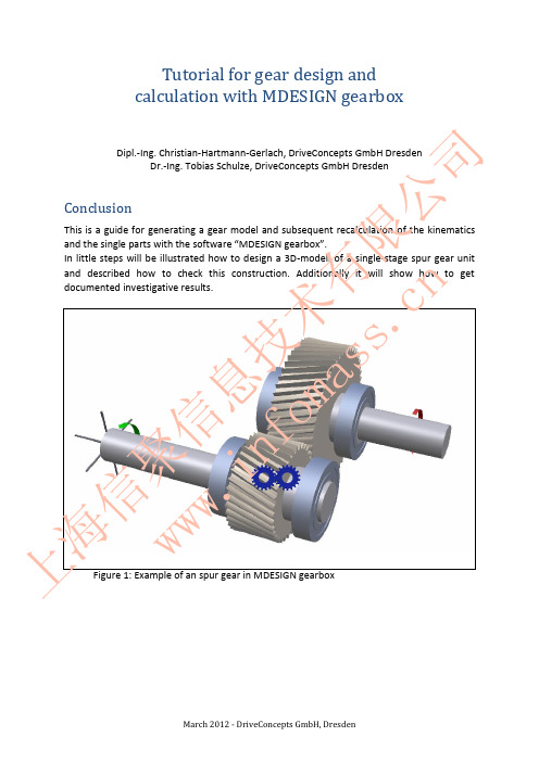
Gear design in MDESIGN gearbox
1. Index
1. 2. 3. 3.1.
Index ............................................................................................................................................ 2 Basic settings for calculation ....................................................................................................... 3 Modeling the gearbox .................................................................................................................. 6 Modeling the shafts ................................................................................................................. 6 Design of spur gears ............................................................................................................. 10 Modeling of bearings ............................................................................................................. 13 Modeling drive and output drive ............................................................................................ 15
壳体设计规范
Needs to be manufactured to tight tolerances to ensure the bore is round and concentric to the shaft axis. 需要严格按照公差加工,以确保该孔的圆度并且于轴的轴线同心。 The amount of interference / clearance depends on the type of bearing and load 轴承与轴承孔之间的配合间隙取决于轴承类型和轴承力 Typical transmission applications the outer race is held in the casing with a interference fit. 传统的变速箱应用,轴承外圈与壳体采用过盈配合 For bearings that require some adjustment during build a transition fit can be employed. 一些需要调整的轴承,一般采用过度配合。 General recommendations 一般建议 Aluminum - 0.001mm of interference per mm of diameter. 铝合金壳-直径方向每毫米过盈量为0.001mm Magnesium - 0.0015mm of interference per mm of diameter. 镁合金壳-直径方向每毫米过盈量为0.0015mm
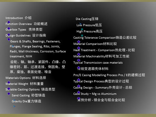
变速器外形尺寸,铸造性能,机械加工
性能 Complexity 复杂性 Influenced by Size and Function
Number of units 组件数量
Small, medium of large volumes 小件,中件,大件 Function功能 Structural, Non structural, Loaded vs Non- Loaded 结构性或者非结构性功能,承载或者非承载结构
二级减速器课程设计完整版

二级减速器课程设计完整版IntroductionThe two-level reduction gear is a mechanical design used to reduce and control the rotational speed and torque of a machine. The mechanism comprises two sets of gears arranged in a series, where the first set reduces the speed while the second set preserves it. The gearboxes are used in various applications in industries, including power transmission, construction, automotive, and aerospace. The design of the gearbox is critical in ensuring that the machine operates efficiently and effectively. This document presents a comprehensive design of the two-level reduction gear course.ObjectiveThe objective of this course is to provide students with a functional understanding of the two-level reduction gear gearboxes' design and application. The course aims to equip students with the skills and knowledge to design and analyze gear systems for various applications in industry. The course will cover critical topics such as gear ratio calculation, kinematics and dynamics analysis, lubrication, and material selection.Course OutlineThe course will run for ten weeks, with two contact hours per week. The course outline includes:Week 1- Introduction to the Two-level Reduction gear- Gearbox design and applications- Types of gears- Concept of gear ratio and its importance- Difference between a two-level reduction gear and a single-level gearWeek 2- Gear Design Principles- Gearing calculations (Lewis equation, AGMA standard)- Design considerations for gear properties (Strength, wear, and contact stress)Week 3- Design of Gear Train- Gear train configurations (simple, compound, and planetary)- The concept of of gear stage and reduction ratio- Mechanics of gear systems- Optimization of gear arrangement for specific applicationsWeek 4- Gear Quality and Precision- Metrics for evaluating gear quality (Material properties, machining tolerances, manufacturing errors)- Gear noise and vibration analysis- Understanding Gear Quality Charts (AGMA 2000)Week 5- Lubrication and Bearing Design- Lubricants and lubrication mechanisms (Boundary, Elastic, Hydrodynamic)- Bearing selection and designWeek 6- Kinematics and Dynamics Analysis of Gear Systems-Learn various kinematic and Dynamic analysis techniques- Familiarize yourself with software used for gear analysisWeek 7- Basic Gear Finite Element Analysis- Applying finite element method to gear design- Objective of FEM Simulation in Gear DesignWeek 8- Non-Standard Gear Applications- Helical, Hypoid gears, and spiral bevel gears- Selecting gear types for specific applicationsWeek 9- Material selection for Gearbox Components- Designing for strength and durability- Materials used in gearbox manufacturing- Heat treatmentWeek 10- Review of the entire course(wrap-up)The course will include Lab sessions and design projects to support the students learning. The lab sessions will focus on developing the practical skills to measure and analyze gear systems. The design projects will challenge the students to apply the knowledge they have acquired throughout the course and design functional gearboxes for specific industrial applications.ConclusionThis course design provides an in-depth understanding of the two-level reduction gear system, which is essential for engineering students' industrial applications. The course will equip students with the skills, knowledge, and experience to design efficient gear systems used in various industries. The course design is flexible and can be customized to suit various academic levels and professional training contexts.。
app-004-Systematic-gear-design

Customer Supplier ProjectDocument KISSsoft AG Uetzikon 4 8634 Hombrechtikon Switzerland www.KISSsoft.ch Title:No.:Date:Manager:@: Version:02 Autor: Date:04.09.2007 Approved: Date:KISSsys application:Systematic gear design using modern software tools 1 Task A complete, three-stage gearbox shall be designed, optimised and integrated into an existing casing. 2 Solution When designing a gearbox, do you start with sketches and CAD or with formulas for strength and power flow analysis?K I S S s y s a p p l i c a t i o n : S y s t e m a t i c a p p r o a c h t o g e a r b o x d e s i g n2.1Start with analysis...Either you choose to start dimensioning the key parts like gears, shafts and axles, bearings and connective elements using formulas for strength and lifetime according to the relevant standards. To accelerate this process, software tools for calculation of machine elements are used. Even now, the engineer goes through several loops since most programs do not allow for analysis of a complete power train or gearbox but only of a gear pair or a single shaft.Once the key parts are dimensioned, the resulting geometry is transferred to CAD drawings or models. To the engineers’ disappointment, he will usually find that the parts do not fit into a design space or that they collide with each other. Back to start.2.2... or with design?Or: you start with drawing the casing, shafts, bearings and gears fitting the geometrical constraints. Here, the engineers experience and intuition helps a lot. Usually, one can start from an existing design. As soon as the drawings have reached a certain level of maturity, one has to check whether the parts designed will withstand the loads and reach the required lifetime. Usually they don’t. Quite a bit of work lost then.Both strategies have the disadvantage that the work is governed by only one aspect of the process of designing a gear box and that the other one is neglected. Loops in the process, a time consuming and de-motivating changing from CAD to CAE and back are the consequences. It would be much more efficient and satisfying to keep both aspects (drawing and analysis) in mind using the same engineering tool. With the existing tools available on the market this is difficult, when designing a complex power train or multi-stage gearbox it is hardly possible.2.3Systematic approachUsing KISSsys, the system program for KISSsoft, the engineer works on a system of machine elements – like a gearbox or a power train - instead of single elements. With KISSsys the power flow and the resulting loads on the elements of the system is calculated and the load data is available for analysis of single elements using KISSsoft automatically. The functions available in KISSsoft for dimensioning gears, shafts and other mechanical elements get much more powerful and flexible to use. When changing data on one element, the power flow is changed/recalculated and the changes in the lifetimes on other elements are visible immediately. Load spectra can be defined on a global level, several variants of a gearbox can be handled in the same model, differential gears and selector gearboxes are possible.The time consuming iteration between different elements in the gearbox is reduced, repetitions of calculations are performed automatically and data handling mistakes are eliminated. The engineer has more time to concentrate on his important work: optimising the gearbox with respect to e.g. lifetime, noise or costs.Furthermore, using KISSsys, both views on the gearbox (geometrical and analytical dimensioning) are handled simultaneously. In the same user interface where the strength analysis is performed, a 3D model of the gear box is available. Each step in the design and optimisation can hence checked for geometrical constraints.A casing can be modelled using simple solids like cuboids and cylinders, to be positioned and arranged in space. Collision checks between casing and gears or shafts can be done in 3D viewer. Pre-defined views are helpful, panning, zooming and rotating is available. In case of doubt, the collision checks can be programmed in detail using data from the gears and casing (dimensions and positions). For this, KISSsys is equipped with a programming language and user interfaces with tables which can be programmed similar to Excel.Standardised interfaces in KISSsoft (like dxf, step and iges) allow for an exchange of data (shaft, gear and bearing geometries) from KISSsys to CAD. Creation of drawings are hence much simplified. Furthermore, manufacturing parameters for gears can be printed automatically and added to manufacturing drawings.3An exampleAn example shall illustrate the advantages of this modern concept: a three-stage gearbox (with helical gears) shall be designed in an existing casing. The engineer has to start from an existing gearbox and optimise the efficiency.3.1BasisIn the following figure, the starting situation is shown. A small actuator with injection moulded gears, three stages, is built based on the data of the existing gearbox. The positions of the input and output shaft is to remain constant, the intermediate shafts are positioned automatically by KISSsys based on the centre distances of the gears. The shafts – steel – are supported by the casing directly (plain bearings). The casings made of plastic too.Figure 3.1-1 3D view of the gearbox with the three stages and the casingThe power flow of the gearbox is represented in KISSsys using a schematic (on the right side). The current power flow is highlighted in red, including power input and output. The mechanical elements and the bearings are shown as symbols, see below. When selecting a symbol in the schematic, an information box appears showing the name of the symbol/part and the respective element is highlighted in the tree structure. This helps when looking for a certain element since navigation in theschematic is much more intuitive than in the tree structure. Furthermore, the element is marked in the 3D view by showing a local co-ordinates system.Figure 3.1-2 Tree structure, tables, 3D view and power flow schematic3.2Integrated analysisFor calculation of the efficiency of the gear box the friction in the gears and even more important the friction in the bearings is relevant. Since the materials for the gears are given, reduction of the friction is focussing on the bearings. The coefficient of friction between the plastic and steel is not known but the power loss of an existing, similar gearbox was measured. Using a separate KISSsys model for said gearbox, the coefficient of friction leading to the measured power loss could be determined for use in the current model. The corresponding value was found to be µ=0.36, see figures below.Figure 3.2-1 User interface for input of analysis parameters and execution thereof. Also, results are shown.The power loss in the bearings is defined by the coefficient of friction and the diameter of the bearings. The smaller the shaft diameter, the smaller the resulting friction moment is. The objective hence was to reduce the shaft diameter for all shafts present. However, due to relatively high loads, the strength and deflection of the shafts was of concern. The diameter of the shafts was hence reduced at the ends of the shafts only. Strength analysis of shafts can either be performed according to the methods by Hänchen + Decker, DIN 743 or FKM Guideline 183 as available from KISSsoft.In a 2D plot the efficiency of the gearbox and the safety against fatigue failure of the critical shaft is shown as a function of bearing diameter. By reducing the shaft diameter from 2.50 mm to 1.25 mm, the efficiency was increased by about 26% from 0.57 to 0.72. The safety factor against fatigue of the shaft was reduced from about 2.40 to a still acceptable value of about 1.95.Figure 3.2-2 Factor of safety of the output shaft (upper line) and efficiency of the gearbox (lower line) as function of the shaft diameter3.3Building a KISSsys modelBuilding a KISSsys model usually is performed by an experienced KISSsys user with administrator rights. Standard users can then use the model and vary input data and optimise them e.g. by parametric studies. The kinematic of the model, the connections between the elements present however can only be changed by the administrator. The distinction between administrators and users ensures that the models are not damaged by inexperienced users.Building a new system does require an amount of effort and profound knowledge of the program while using an existing model to perform an analysis is easy. Therefore, KISSsys models can also be used by e.g. sales representatives or even customers of gearboxes to study the behaviour of a particular gearbox under customer specific parameters (e.g. loads or lubrication). It is a most useful tool since it allows for access to expert know how. For example, a complete product line can be modelled in a single KISSsys model and is the available as a form of interactive product catalogue. The, e.g. during a sales presentation, the strength of the gears, lifetime of bearings or other technical aspects can be answered immediately by the sales representative using such KISSsys models.4 ConclusionUsing this systematic approach to gear design, the following advantages are used:Keep both aspects (geometrical and analytical design) of the complete gear box under control at any timeCollaboration between gear expert, design engineer and sales representativeData exchange between CAE and CAD through standardised interfacesSimple and safe management of design, manufacturing and strength/lifetime specific data Optimisation and proof of integrity of all mechanical elements involved according to DIN, ISO and AGMA standard using state of the art analysis methodsUsing KISSsys, the work of the gearbox designer is accelerated, simplified, less prone to errors and hence more interesting and rewarding.。
力士乐行走减速机样本
HYDROTRAC GFT !"#$%$&'(
RC 77 112/10.04
4
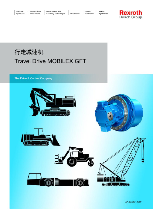
MOBILEX GFT
Mobile Hydraulics Gear Technology
Description
Sealing
Tightness of the joint between stationary and rotating gear-box sections is ensured by means of a high-grade axial mechanical seal so as to prevent moisture and dirt entering the gear unit even under extreme operating conditions.
!"#$%&'()*+&,-./01&2345 !"#$% !"#$%&' !" #$%&' !"
HYDROTREAC GFT
as wheel drive in an harvesting machine
HYDROTRAC GFT !"#$%&'
Oil changing
Save for regular oil changes the drive units do not require maintenance.Changing the oil is done very easily. Exclusively the oil brands recommended in the operating manual must be used for this work.
轿车三轴五档汽车变速器说明书
毕业设计题目学院专业姓名学号指导教师二OO 年月日三轴五档汽车变速器设计Three-axis gearbox design of the five stallacars专业:学生:指导教师:学院二零零年月目录摘要 (i)ABSTRACT (ii)第一章前言 (1)手动变速器(MT) (1)自动变速器(AT) (2)手动/自动变速器(AMT) (2)无级变速器 (3)第二章机械式变速器的概述及其方案的肯定 (5)变速器的功用和要求 (5)变速器结构方案的肯定 (5)2.2.1变速器传动机构的结构分析与型式选择 (5)2.2.2倒档传动方案 (7)变速器主要零件结构的方案分析 (8)第三章变速器主要参数的选择与主要零件的设计 (12)变速器主要参数的选择 (12)3.1.1档数和传动比 (12)3.1.2中心距 (13)3.1.3轴向尺寸 (13)3.1.4齿轮参数 (14)各档传动比及其齿轮齿数的肯定 (15)3.2.1肯定一档齿轮的齿数 (15)3.2.2肯定常啮合齿轮副的齿数 (16)3.2.3肯定其他档位的齿数 (16)3.2.4肯定倒档齿轮的齿数 (16)齿轮变位系数的选择 (17)第四章变速器齿轮的强度计算与材料的选择 (19)齿轮的损坏原因及形式 (19)齿轮的强度计算与校核 (19)4.2.1齿轮弯曲强度计算 (19) (21)4.2.2齿轮接触应力j第五章变速器轴的强度计算与校核 (23)变速器轴的结构和尺寸 (23)5.1.1轴的结构 (23)5.1.2肯定轴的尺寸 (24)轴的校核 (24)5.2.1第一轴的强度与刚度校核 (24)5.2.2第二轴的校核计算 (25)第六章变速器同步器的设计及操纵机构 (28)同步器的结构 (28)同步环主要参数的肯定 (29)变速器的操纵机构 (31)第七章小结 (33)致谢 (34)参考文献 (35)摘要本设计的任务是设计一台用于轿车上的FR式的手动变速器。
EQ1090载货汽车变速器的设计

第4章变速器各档齿轮的校核14
4.1齿轮弯曲应力的计算14
4.1.1二轴一倒挡直齿轮Z5校核14
4.1.2二轴二挡斜齿轮Z4校核15
4.1.4二轴三挡斜齿轮Z 校核15
4.2齿轮接触应力计算16
4.2.1二轴一挡直齿轮Z 校核16
4.2.2二轴倒挡直齿轮Z 校核17
摘要
变速器是汽车的主要组成部分,其功能是改变传动比、改变驱动轮的扭矩和转动方向。变速器能在发动机旋转方向不变的前提下,使汽车倒退行驶,而且利用挡位可以中断动力的传递。所以变速器的结构设计的合理性直接影响到汽车动力性和经济性。设计要求达到换挡迅速、省力、方便、有较高的工作效率、工作噪声低。因此变速器在汽车中得到广泛应用。
设计结论表明,变速器齿轮及各轴尺寸确定,各轴强度的校核满足设计要求,设计结构合理。
关键词:货车;பைடு நூலகம்速器;设计;同步器
Abstract.
Gearbox is the key part of theautomobile. It is used to change the transmission ratio, torque and runningdirection of the driving wheel.It can changethevehicle speed and tyre torque in a big scope, cut off the power transfer from the engine, and also provides a reverse traveling direction for the vehicle. Therefore, the reasonability of the structure design of a transmission gearbox directly affects the vehicle's dynamic performance. It is usually required shifting gears rapidly and conveniently, saving force, and having a higher working efficiency and low working noises.
- 1、下载文档前请自行甄别文档内容的完整性,平台不提供额外的编辑、内容补充、找答案等附加服务。
- 2、"仅部分预览"的文档,不可在线预览部分如存在完整性等问题,可反馈申请退款(可完整预览的文档不适用该条件!)。
- 3、如文档侵犯您的权益,请联系客服反馈,我们会尽快为您处理(人工客服工作时间:9:00-18:30)。
Gearbox DesignFUNCTION OF A CAR TRANSMISSION GEARBOXYour vehicle transmission system will include a gearbox for the following reasons:∙The gearbox will help the engine drive the car.∙The gearbox will enable the vehicle to be reversed∙The gearbox will connect the engine to the transmission systemThe first point is obvious if you try to calculate the cylinder size you would need if you had to generate the required wheel torque at the engine shaft. You obviously cannot have a locomotive size engine driving your racing car. If you think a bit further along these lines, you would realise that the "required wheel torque" is not constant. You need a high torque to accelerate the car but the cruising torque does not need to be as high. This means your gearbox needs to be capable of different speed ratios.The second point does not need any elaboration.The third point is really a statement indicating a need for easily connecting/disconnecting engine from the transmission system. This is usually done by including a clutch between the engine and the gearbox.MULTI-SPEED GEARBOXESAutomotive gearboxes must be capable of operating more than one speed reduction to accommodate differen torque requirements under different conditions. In this project you are asked to design a five-speed gearbox (four forward and one reverse).Sliding MeshThe first cars (and we are talking about 1890s) used to have gears sliding into and out of mesh as seen in the following figure.You can imagine the difficulty of finding the right moment to slide the output gear into the mesh without destroying the gearbox. It would be virtually impossible to achieve a mesh without the teeth grinding against each other first. The gears would not survive too long with this arrangement. In the words of its inventor, Levassor, "it was brutal but it worked".Constant-mesh GearThe output gear is permanently in mesh but rotates freely on the output shaft until it is engaged by using a sliding dog clutch. A SLIDING DOG CLUTCH is a positive locking device to connect the gears to the shaft. You may want to check the following web page for schematic description of a four-speed (plus reverse) gearbox with constant-mesh gears and sliding dog clutches: John Kelly Technology CollegeHOW TO CHANGE GEARSDesigning a mechanism to let the driver select the desired gear ration can be quite complicated. For the purpose of this project, it is acceptable if you use of one of the earliest designs, a multi-rail gear selector. No car is manufactured with a multi-rail gear selector but is relatively easier to understand and to design. Here is an example of a multi-rail gear selector (Automotive Technology by M J Nunney, SAE Publications). You are free to explore your own version.The above is a schematic drawing. Some features are not clearly defined. For example, it is not clear hw the gear lever and selector finger work to select and push different selector rods. Your drawings should not have any ambiguity and all components must be clearly defined.DESIGNING A GEARBOX FOR DURABILITY AND STRENGTHIn addition to having the right number of gears and capability to reduce the speed at desired ratios, your gearbox must be designed to provide adequate strength and durability.The following components require special attention:The GearsFirst decide on what type of gear you want to use. Since the shafts are typically parallel in this type of gearbox, the choice is between helical gears and spur gears. Helical gears are generally the preferred choice for the two simple reasons:∙they are typically quiter and smoother∙for the same width, they have a higher rating, which means a more compact gearbox.Unfortunately, helical gears will not easily slide into and out of meshes. Therefore, in this Assignment, you may have to use spur gears.It is assumed that you already know how to design gears. I expect that you will calculate the load bearing capacity for the gear meshes and demonstrate that it is lower than the loads you expect for this project. You must consider static as well as dynamic loads and static strength as well as fatigue life considerations.You are reminded that the load bearing capacity for gear meshes is typically based on the following failure modes:∙Surface Pitting: pitting is failure of the gear surface by production of small holes. All gear meshes produce some initialpitting but the holes produced during this stage usually disappear with usage. When the surface is loaded beyond its rated capacity, the holes grow with usage, eventually leading to tooth breakage.The pitting rating for your gears must be high enough to avoid this.∙Breakage : Sometimes teeth break due to the bending stresses experienced at the root area. This failure may occur due to overload or due to fatigue. In either case, it is a dangerous form of failure and should be avoided. The resistance against tooth breakage in this form is expressed in terms of a Bending Rating, which should behigher than the operating loads.The ShaftsThe shafts must be designed against failure by overload as well as fatigue. There are well-established to design shafts and you are referred to appropriate standards or design textbooks.Mounting the gears onto the shaftsYou must design the method by which the gears are fitted onto the shafts. Some choices are splines, shrink fits or keys.You have a free choice but should demonstrate the fitness of your design choice in terms of torque rating, ease of assembly/disassembly, and any other factors that are applicable.You must make sure that your shaft (and hub diameters if applicable) have tolerances. You cannot produce shafts and hubs to precise dimensions. The higher the precision, the higher the manufacturing cost of delivering thatprecision. There are standard shaft/hub tolerances that you need to comply with. Again you are referred to appropriate standards or design textbooks.BearingsThe shafts are supported by bearings. Select approriate type and size of bearing based on the following considerations:∙Load magnitudes∙Load directions∙Space limitationsThe tolerancing between the bearing seat and the shaft needs to be specified as it is in the gear/shaft interface.The bearings need to be mounted on your gearbox casing. Therefore, your gearbox casing needs to be strong enough to resist the shaft support loads.Gearbox HousingThe gearbox housing or casing serves the following functions: ∙Support the bearing housings as noted above∙Contain the lubricant∙Keep the gears in contactThe first two functions are obvious. The last one refers to the requirement of the gearbox to resist the torque. This is either done by designing a flange-mounted gearbox or by fixing the gearbox on the "floor", ie chassis. In this project, there are obvious reasons against using a floor-mounted gearbox. You must be able to figure out what they are.LubricationLubricants in a gearbox serve the following functions:∙reduce the coefficient friction between mating surfaces∙remove the dissipation heat∙protect bearings and gears against external contaminantsThe heat is caused by friction and this corresponds to a loss from your useful power. The gearbox efficiencies typically range from 90% to 98%.The last function needs gaskets and seals at the input and output shafts.You must consider lubrication in your design. This consideration must include choice of lubricant and mode of lubrication. We will cover some aspects of lubrication in the lecture on Tribology.MAIN CLUTCHIt is difficult to change gears when the gear train is transmitting torque. Therefore, you need a clutch between the gearbox and the engine to disengage the gearbox while switching gears.There are three functions that the clutch should accomplish: ∙enable changinggears while in motion∙connect a running engine smoothly to the transmission∙enable temporary stoppage without bringing the gear to neutral or without stopping the engineThe following figure gives different clutch configurations:Source : Automotive Technology, M J Nunney. SAE Publications.One important design constraint for the clutch is to have as small an inertia as possible. Why?The plate clutch is replacing the old friction clutch mainly because of this reason.The following describes the operation of a spring-loaded friction clutch.A clutch coupling consist of plates squeezed between two shafts. The compressive force may be provided hydraulically or by a mechanical spring. In the latter case, the force may be adjusted by electro-magnetic action. The magnitude of the force determines the torque rating for the coupling:whereF Spring Force, NFriction coefficientN Number of contact surfaces (one less than the number of plates) R Outer radius for the contact area, mr Inner radius for the contact area, mSome representative friction factors:Steel on dry steel 0.3 - 0.4Steel on lubricated steel 0.06 - 0.1Steel on cast iron 0.1 - 0.2Steel on rubber 0.2 - 0.4Rubber on rubber 0.4 - 0.6。