Gear and gearbox_2018
AGMA Standards-美国齿轮标准

AGMA 217.01AGMA 900-H06AGMA 901-A92AGMA 904-C96AGMA 908-B89AGMA 910-C90AGMA 911-A94AGMA 912-A04AGMA 913-A98AGMA 914-B04AGMA 915-1-A02AGMA 915-2-A05AGMA 915-3-A99-1999AGMA 917-B97AGMA 918-A93AGMA 920-A01AGMA 922-A96AGMA 923-B05AGMA 925-A03AGMA 926-C99-1999AGMA 927-A01AGMA 930-A05AGMA 931-A02AGMA 932-A05AGMA 933-B03AGMA 935-A05AGMA 938-A05AGMA ISO 10064-1AGMA ISO 10064-2AGMA ISO 10064-5-A06 AGMA ISO 14179-1ANSI/AGMA 1003-G93 (R1999) ANSI/AGMA 1006-A97 (R2003) ANSI/AGMA 1010-E95 (R2004) ANSI/AGMA 1012-2005ANSI/AGMA 1102-A03ANSI/AGMA 1106-A97 (R2003) ANSI/AGMA 2000-A88ANSI/AGMA 2001-D04ANSI/AGMA 2002-B88 (R1996) ANSI/AGMA 2003-B97 (R2003) ANSI/AGMA 2004-B89 (R2006) ANSI/AGMA 2005-D03ANSI/AGMA 2007-C00ANSI/AGMA 2008-C01ANSI/AGMA 2009-B01ANSI/AGMA 2011-A98ANSI/AGMA 2015-1-A01ANSI/AGMA 2015-2-A06ANSI/AGMA 2101-D04ANSI/AGMA 2111-A98ANSI/AGMA 2116-A05ANSI/AGMA 6000-B96 (R2002) ANSI/AGMA 6001-D97 (R2003) ANSI/AGMA 6002-B93 (R2001) ANSI/AGMA 6004-F88 (R1996)ANSI/AGMA 6005-B89 (R1996) ANSI/AGMA 6008-A98ANSI/AGMA 6011-I03ANSI/AGMA 6013-A06ANSI/AGMA 6022-C93 (R2000) ANSI/AGMA 6023-A88 (R2000) ANSI/AGMA 6025-D98ANSI/AGMA 6033-B98ANSI/AGMA 6034-B92 (R1999) ANSI/AGMA 6035-2002ANSI/AGMA 6113-A06ANSI/AGMA 6123-A06ANSI/AGMA 6133-B98ANSI/AGMA 6135-2002ANSI/AGMA 9000-C90 (R2001) ANSI/AGMA 9001-B97 (R2003) ANSI/AGMA 9002-B04ANSI/AGMA 9003-A91 (R1999) ANSI/AGMA 9004-A99ANSI/AGMA 9005-E02ANSI/AGMA 9008-B00 (R2006) ANSI/AGMA 9009-D02ANSI/AGMA 9112-A04ANSI/AGMA ISO 1328-1ANSI/AGMA ISO 1328-2ANSI/AGMA ISO 18653-A06ANSI/AGMA/AWEA 6006-A03 Supplemental Tables for AGMA 2015 AGMA 6006-A03ANSI/AGMA 6009-A00ANSI/AGMA 6109-A00ANSI/AGMA 6110-F97 (R2003)Information Sheet - Gear Scoring Design for Aerospace Spur and Helical Power GearsStyle Manual for the Preparation of Standards, Information Sheets and Editorial ManualsA Rational Procedure for the Preliminary Design of Minimum Volume GearsMetric UsageInformation Sheet - Geometry Factors for Determining the Pitting Resistance and Bending Strength of Spur, HelicFormats for Fine-Pitch Gear Specification DataDesign Guidelines for Aerospace GearingMechanisms of Gear Tooth FailureMethod for Specifying the Geometry of Spur and Helical GearsGear Sound Manual - Part I: Fundamentals of Sound as Related to Gears; Part II: Sources, Specifications and Levels of G Inspection Practices - Part 1: Cylindrical Gears - Tangential MeasurementsInspection Practices - Part 2: Cylindrical Gears - Radial MeasurementsInspection Practices - Gear Blanks, Shaft Center Distance and Parallelism"Design Manual for Parallel Shaft Fine-Pitch GearingA Summary of Numerical Examples Demonstrating the Procedures for Calculating Geometry Factors for Spur an Materials for Plastic GearsLoad Classification and Service Factors for Flexible CouplingsMetallurgical Specifications for Steel GearingEffect of Lubrication on Gear Surface DistressRecommended Practice for Carburized Aerospace GearingLoad Distribution Factors - Analytical Methods for Cylindrical GearsCalculated Bending Load Capacity of Powder Metallurgy (P/M) External Spur GearsCalibration of Gear Measuring Instruments and Their Application to the Inspection of Product GearsRating the Pitting Resistance and Bending Strength of Hypoid GearsBasic Gear GeometryRecommendations Relative to the Evaluation of Radial Composite Gear Double Flank TestersShot Peening of GearsCylindrical Gears - Code of Inspection Practice - Part 1: Inspection of Corresponding Flanks of Gear TeethCylindrical Gears - Code of Inspection Practice - Part 2: Inspection Related to Radial Composite Deviations, Runout, Tooth Code of Inspection Practice - Part 5: Recommendations Relative to Evaluation of Gear Measuring InstrumentsGear Reducers - Thermal Capacity Based on ISO/TR 14179-1Tooth Proportions for Fine-Pitch Spur and Helical GearingTooth Proportions for Plastic GearsAppearance of Gear Teeth - Terminology of Wear and FailureGear Nomenclature, Definitions of Terms with SymbolsTolerance Specification for Gear HobsTooth Proportions for Plastic Gears (Metric Version of ANSI/AGMA 1006-A97)Gear Classification and Inspection Handbook - Tolerances and Measuring Methods for Unassembled Spur and H Fundamental Rating Factors and Calculation Methods for Involute Spur and Helical Gear TeethTooth Thickness Specification and MeasurementRating the Pitting Resistance and Bending Strength of Generated Straight Bevel, Zerol Bevel and Spiral Bevel Gear Teeth Gear Materials and Heat Treatment ManualDesign Manual for Bevel GearsGears - Surface Temper Etch Inspection After GrindingAssembling Bevel GearsBevel Gear Classification, Tolerances and Measuring MethodsCylindrical Wormgearing Tolerance and Inspection MethodsAccuracy Classification System - Tangential Measurements for Cylindrical GearsAccuracy Classification System - Radial Measurements for Cylindrical GearsFundamental Rating Factors and Calculation Methods for Involute Spur and Helical Gear Teeth (Metric Edition) Cylindrical Wormgearing Tolerance and Inspection Methods (Metric)Evaluation of Double Flank Testers for Radial Composite Measurement of GearsSpecification for Measurement of Linear Vibration on Gear UnitsDesign and Selection of Components for Enclosed Gear DrivesDesign Guide for Vehicle Spur and Helical GearsGear Power Rating for Cylindrical Grinding Mills, Kilns, Coolers, and DryersPower Rating for Helical and Herringbone Gearing for Rolling Mill ServiceSpecifications for Powder Metallurgy GearsSpecification for High Speed Helical Gear UnitsStandard for Industrial Enclosed Gear DrivesDesign Manual for Cylindrical WormgearingDesign Manual for Enclosed Epicylic Gear DrivesSound for Enclosed Helical, Herringbone, and Spiral Bevel Gear DrivesMarine Propulsion Gear Units, Part 1 - MaterialsPractice for Enclosed Cylindrical Wormgear Speed Reducers and GearmotorsDesign, Rating and Application of Industrial Globoidal WormgearingStandard for Industrial Enclosed Gear Drives (Metric Edition)Design Manual for Enclosed Epicyclic Gear DrivesMaterials for Marine Propulsion GearingDesign, Rating and Application of Industrial Globoidal Wormgearing (Metric Edition)Flexible Couplings - Potential Unbalance ClassificationFlexible Couplings - LubricationBores and Keyways for Flexible Couplings (Inch Series)Flexible Couplings - Keyless FitsFlexible Couplings - Mass Elastic Properties and Other CharacteristicsIndustrial Gear LubricationFlexible Couplings - Gear Type - Flange Dimensions, Inch Series (Also listed as 9008-B99)Flexible Couplings - Nomenclature for Flexible CouplingsBores and Keyways for Flexible Couplings (Metric Series)Cylindrical Gears - ISO System of Accuracy - Part 1: Definitions and Allowable Values of Deviations Relevant to Correspon Cylindrical Gears - ISO System of Accuracy - Part 2: Definitions and Allowable Values of Deviations Relevant to Radial Co Gears - Evaluation of Instruments for the Measurement of Individual GearsDesign and Specification of Gearboxes for Wind TurbinesAccuracy Classification System - Tangential Measurement Tolerance Tables for Cylindrical GearsStandard for Design and specification of Gearbox for Wind Turbines (Spersedes AGMA 921 - A97)Standard for Gearmotor, Shaft Mounted and Screw Conveyor DrivesStandard for Gearmotor, Shaft Mounted and Screw Conveyor Drives (metric version)Spur, Helical, Herringbone, and Bevel Enclosed DrivesAGMA Technical CommitteeAGMA Technical CommitteeAGMA Technical CommitteeAGMA Technical CommitteeAGMA Technical CommitteeAGMA Technical Committeecifications and Levels of Gear Sound; Part III: Gear Noise ControlAGMA Technical CommitteeAGMA Technical CommitteeDeviations, Runout, Tooth Thickness and BacklashInstrumentsAGMAAGMASpiral Bevel Gear TeethAGMAAGMAAGMAMetric Edition)AGMAAGMAAGMAAGMAAGMAAGMAAGMAns Relevant to Corresponding Flanks of Gear Teethns Relevant to Radial Composite Deviations and Runout Information in GE libraries while not listed herelisted in sheet ver3 while missed in ver4listed in sheet ver3 while missed in ver4listed in sheet ver3 while missed in ver4AGMA+217.01.pdf46 AGMA+900-H06.pdf30 AGMA+901-A92.pdf42 AGMA+904-C96.pdf42 AGMA+908-B89.pdf84 AGMA+910-C90.pdf51 AGMA+911-A94.pdf96 AGMA+912-A04.pdf70 AGMA+913-A98.pdf58 AGMA+914-B04.pdf76 AGMA+915-1-A02.pdf105 AGMA+915-2-A05.pdf47 AGMA+915-3-A99-1999.pdf42 AGMA+917-B97+.pdf84 AGMA+918-A93.pdf68 AGMA+920-A01.pdf58 AGMA+922-A96.pdf42 AGMA+923-B05.pdf79 AGMA+925-A03.pdf69 AGMA+926-C99-1999.pdf48 AGMA+927-A01.pdf69 AGMA+930-A05.pdf83 AGMA+931-A02.pdf63 AGMA+932-A05.pdf60 AGMA+933-B03.pdf37 AGMA+935-A05.pdf40 AGMA+938-A05.pdf45 AGMA+ISO+10064-1.pdf75 AGMA+ISO+10064-2.pdf55 AGMA+ISO+10064-5-A06.pdf145 AGMA+ISO+14179-1.pdf69 ANSI+AGMA+1003-G93+(R1999).pdf68 ANSI+AGMA+1006-A97+(R2003).pdf68 ANSI+AGMA+1010-E95+(R2004).pdf96 ANSI+AGMA+1012-2005.pdf82 ANSI+AGMA+1102-A03.pdf82 ANSI+AGMA+1106-A97+(R2003).pdf62 ANSI+AGMA+2000-A88.pdf140 ANSI+AGMA+2001-D04.pdf167 ANSI+AGMA+2002-B88+(R1996).pdf90 ANSI+AGMA+2003-B97+(R2003).pdf145 ANSI+AGMA+2004-B89+(R2006).pdf96 ANSI+AGMA+2005-D03.pdf167 ANSI+AGMA+2007-C00.pdf37 ANSI+AGMA+2008-C01.pdf68 ANSI+AGMA+2009-B01.pdf101 ANSI+AGMA+2011-A98.pdf84 ANSI+AGMA+2015-1-A01.pdf84 ANSI+AGMA+2015-2-A06.pdf40 ANSI+AGMA+2101-D04.pdf140 ANSI+AGMA+2111-A98.pdf74 ANSI+AGMA+2116-A05.pdf38 ANSI+AGMA+6000-B96+(R2002).pdf73 ANSI+AGMA+6001-D97+(R2003).pdf84 ANSI+AGMA+6002-B93+(R2001).pdf68 ANSI+AGMA+6004-F88+(R1996).pdf84ANSI+AGMA+6005-B89+(R1996).pdf79 ANSI+AGMA+6008-A98.pdf56 ANSI+AGMA+6011-I03.pdf95 ANSI+AGMA+6013-A06.pdf159 ANSI+AGMA+6022-C93+(R2000).pdf73 ANSI+AGMA+6023-A88+(R2000).pdf84 ANSI+AGMA+6025-D98.pdf79 ANSI+AGMA+6033-B98.pdf84 ANSI+AGMA+6034-B92+(R1999).pdf56 ANSI+AGMA+6035-2002.pdf79 ANSI+AGMA+6113-A06.pdf135 ANSI+AGMA+6123-A06.pdf140 ANSI+AGMA+6133-B98.pdf74 ANSI+AGMA+6135-2002.pdf74 ANSI+AGMA+9000-C90+(R2001).pdf62 ANSI+AGMA+9001-B97+(R2003).pdf42 ANSI+AGMA+9002-B04.pdf55 ANSI+AGMA+9003-A91+(R1999).pdf51 ANSI+AGMA+9004-A99.pdf69 ANSI+AGMA+9005-E02.pdf84 ANSI+AGMA+9008-B00+(R2006).pdf38 ANSI+AGMA+9009-D02.pdf49 ANSI+AGMA+9112-A04.pdf53 ANSI+AGMA+ISO+1328-1.pdf63 ANSI+AGMA+ISO+1328-2.pdf42 ANSI+AGMA+ISO+18653-A06.pdf75 ANSI+AGMA+AWEA+6006-A03.pdf208 Supplemental+Tables+for+AGMA+20137。
2018 Honda Gold Wing 商品说明书

2018GOLD WING WHAT LIES BEYOND?What lies over the horizon? Beyond our town, our state? Beyond the predictable, the expected?And what’s the best way to experience it? We ride motorcycles because they’re such engaging,active, personal vehicles. Travel the same roads in a car and on a bike, eat at the same restaurants,see the same sights, and then tell us which trip is the most memorable.Honda’s 2018 Gold Wing® is an all-new motorcycle this year, designed to put you more in touchwith the essential experience of riding. Changing a bike as good and as refined as a Gold Wing isn’tsomething you undertake lightly. So we set out to improve the newest model in every category:Engineering. Handling. Technology. Comfort. Performance. The new Gold Wing is lighter, morepowerful, more nimble, and more engaging. It’s a better motorcycle in every way. What liesbeyond? Ride there and find out.YEARS OF ADVENTURE.THE FIRST GOLD WING—THE 1975 GL1000—WAS REVOLUTIONARY, A MOTORCYCLE THAT OFFERED SUPERBIKE-LEVEL POWER, INCREDIBLE SMOOTHNESS, LIQUID COOLING, SHAFT DRIVE, AND A HOST OF TECHNICAL INNOVATION UNMATCHED AT THE TIME IN THE MOTORCYCLING WORLD. RIDERS ACROSS THE GLOBE RECOGNIZED THE GENIUS IN THIS MACHINE, BUT ESPECIALLY RIDERS WHO WANTED TO COVER LONG DISTANCES. AND SO THE GOLD WING BECAME A TOURING ICON. OVER THE YEARS WE ADDED BODYWORK, SADDLEBAGS, AND INCREASED THE ENGINE SIZE. NOW IT’S TIME TO GO BACK TO OUR ROOTS, TO THE KIND OF PERFORMANCE AND HANDLING THAT MADE THOSE FIRST GOLD WINGS SUCH AWESOME BIKES. HANG ON, AND ENJOY THE RIDE!GOLD WING TOURThe Honda Gold Wing is probably the best-known bike in all of motorcycling, a machine that single-handedly defines what a touring bike should be. But now it’s time to forget just about everything you thought you knew this bike was, because the new 2018 Gold Wing and Gold Wing Tour are designed for the way we ride today. Maybe in high school or college you had a coach who taught you something called the athletic stance. Poised,balanced, feet spread about shoulder’s width apart, leaning forward slightly. It’s theway you stood on a basketball court, on a football field, or ready to rush the net on atennis court. It’s the same with motorcycling. The new Gold Wing Tour and Gold WingGOLD WINGare designed to be more athletic, more engaging, to give you a greater sense of beingone with your bike. The difference between the two? The Gold Wing Tour has a tallerwindscreen, a trunk, and a full complement of touring-bike features. The Gold Wingis lighter, uses a shorter windscreen, and features no-nonsense blacked-out styling.Navigation is now a standard feature, and both the Gold Wing and the Gold Wing Touralso feature standard Anti-Lock Brakes (ABS) as well. We think you’ll find that these arethe best Gold Wings you’ve ever ridden. They’re also the most engaging and fulfilling toride. And the more you ride them, the better they’re going to feel.INTRODUCING THE NEW GOLD STANDARDS OF TOURING.COUNTER-ROTATING TRANSMISSION / Mounting the Gold Wing’stransmission below the crankshaft, and spinning it opposite the crank’s rotation helps neutralize any engine torque reaction. Combining the alternator and starter into one integrated unit is one reason why the new Gold Wing’s engine is over 13 pounds lighter!*COMPACT 4-VALVE ENGINE / The new Gold Wing’s engine is all aboutathletic performance. The horizontally opposed six-cylinder design is still super smooth, except now it makes even more power. Plus, nothing can match it when it comes to a low center of gravity—a key to superior handling and parking-lot maneuverability.7-SPEED AUTOMATIC DCT6-SPEED MANUAL TRANSMISSIONThis is huge news for 2018. For the first time ever, both the Gold Wing and the Gold Wing Tour are available with a brand new 7-Speed Automatic DCT. If you’re not familiar with it, think of the paddle-shift gearboxes Formula 1 cars use.DCT stands for Dual-Clutch Transmission. Inside, the transmission looks like a normal manual, with strong, efficient, constant-mesh steel gears. But there’s no shift lever and no clutch lever—all your shifting is controlled by buttons on the handlebar. Or you can let the DCT function fully automatically, and the bike will upshift and downshift effortlessly. The twin clutch packs, one for odd gears, one for even, makes shifting quick and seamless. The DCT has been a big hit on many Honda motorcycles, and our Africa Twin ® has proven it’s tough enough for fully loaded off-road travel. But the 2018 Gold Wings have the best DCT we’ve ever offered, and the first with seven speeds. Even better, our DCT models offer a special low-speed “Walking” mode in addition to reverse (see our Models and Options chart for more information). It’s a huge help whenmaneuvering into or out of parking spaces with a passenger on the back.We know plenty of Gold Wing riders still prefer a traditional manual transmission. Fear not—we have you covered. You can opt for a conventional gearbox on both the Gold Wing and Gold Wing Tour models. But we’ve gone ahead and made it even better for 2018, by adding a sixth speed. Closing up the gearbox ratios makes it easier to pick the perfect gear for sportier riding, yet the overdrive sixth still serves up relaxed top-gear cruising.THE BEST SPORTS CARS IN THE WORLD USE THEM. AND NOW THE BEST BIKES DO, TOO.APPLE CARPLAY INTEGRATION / A firstfor the motorcycle industry! Apple CarPlay TMseamlesslyintegrates your iPhone ® into your new Gold Wing. That means you can use your iPhone to access Apple Maps, Apple Music ® and other services. You’ll have access to weather, playlists and telephone numbers while aboard. Available Bluetooth ®-enabled wireless headsets let you communicate easily.** And best of all, with more apps available every day, Apple CarPlay keeps your bike’s technology on the cutting edge.HOMELINK / Available as an optional feature,HomeLink ® lets you integrate your new Gold Wing with other devices in your home. A typical example: you can open your home’s garage door without any dedicated controller—just touch a switch on your bike’s center console. No more fumbling, and no hassle.METERS / The new Gold Wing’s cockpit meters areinformation central. In addition to the basics like vehicle and engine speed, fuel level, engine temperature and dual tripmeters, you can also monitor outside air temperature, cruise-control speed, heater levels, and more.NAVIGATION / Electronic navigation just keeps getting better andmore convenient, and your Gold Wing and Gold Wing Tour are right on the cutting edge. Both are equipped with an excellent, dedicated, GPS-based navigation system. It’s a feature-rich, stand-alone system that’s completely independent of the Apple CarPlay navigation. No phone or cell reception? No problem— your navi system doesn’t need them.AUDIO / Your new Gold Wing’s premium audio system isan excellent example of state-of-the-art electronic technology. In addition to listening to music, with an available Bluetooth headset you can make or answer phone calls without taking off your helmet. A dedicated port lets you plug in a USB flash drive. Options include a separate passenger audio control switch, high-output amplifier and speakers, a CB radio, and more.AUDIO SYSTEMNAVIGATIONMETERSAPPLE CARPLAY INTEGRATIONHOMELINK SYSTEMTECHNOLOGY / NAVIGATIONA hundred years ago, cars had hand-cranked engines, motorcycles had manual spark advances, and your telephone—if you had one—was a wooden box screwed to the wall. Who wants to go back to that? Technology is part of our lives today, and the smart motorcyclist embraces it. So do the new Gold Wings. They offer a suite of technologic/electronic features that make planning and riding easier, freeing you up to enjoy the parts of riding where you really want to pay attention. A large, bright seven-inch LCD/TFT display is front and center, giving you all the information you want.0102050306ELECTRIFYING INNOVATION.Modern motorcycle electronics let the new Gold Wings offer acollection of features impossible to imagine just a few years ago, andthe stuff of science-fiction movies when the first Gold Wing appeared.Some are convenience features, some rider aids. Together, they makeyour new Gold Wing more fun and more enjoyable to ride.04Shown with optional accessories.01 030205 04ATHLETIC COMFORT.How you sit on a motorcycle determines how you’ll perform. A well-designed office chair, or the pilot’s seat in a fighter jet are designed to keep you alert, active, and engaged for an entire day. That’s the philosophy behind the new 2018 Gold Wing and Gold Wing Tour. And an added plus: you’ll find your new Gold Wing is just as much fun for shorter, around-town rides as it is on long trips.GOLD WING SPECIFICATIONSENGINE TYPE 1833cc liquid-cooled horizontally opposed six-cylinder BORE AND STROKE 73mm x 73mmINDUCTION Programmed Fuel Injection (PGM-FI)IGNITION Computer-controlled digital with three-dimensional mapping COMPRESSION RATIO10.5:1VALVE TRAIN SOHC Unicam; four valves per cylinderFINAL DRIVE ShaftFRONT SUSPENSION Double A-arm fork with single coil-over shock absorber; 4.3 inches of travel REAR SUSPENSION Pro Arm® single-sided swingarm with Pro-Link® single shock; computer-controlled spring-preload adjustment with four presets; 4.1 inches of travelLUGGAGE CAPACITY110 liters (Gold Wing Tour) / 60 liters (Gold Wing) WHEELBASE66.7 inchesTIRE SIZE130/70R-18 front; 200/55R-16 rearSEAT HEIGHT29.3 inchesFUEL CAPACITY 5.55 gallonsFUEL ECONOMY†42 MPGFreedom of Choice.One style, one size, one color is never a great fit. That’s why we’re offering five distinct Gold Wing models for 2018, and six color options. Which new Gold Wing model is the right one for you?MODELS AND OPTIONSGOLD WINGTOUR DCTAIRBAGGOLD WINGTOUR DCTGOLD WINGTOURGOLD WINGDCT GOLD WING1833cc Six-CylinderEngine X X X X X Seven-Speed AutomaticDCT Transmission X X XSix-Speed ManualTransmission X XTrunk X X XReverse X X X XWalking Mode X X XApple CarPlay X X X X XElectric Windscreen X X X X XSelectable Ride Modes X X X X XCruise Control X X X X XHill Start Assist X X X X XHonda SelectableTorque Control (HSTC)X X XHeated Seats X X XHeated Grips X X X X XTire PressureMonitoring System X X X X XElectronic RearSuspension Preload X X XCurb Weight◊842833833800787◊ Includes all standard equipment, required fluids and a full tank of fuel—ready to ride02 GOLD WING ACCESSORIES:03 0504 01Gold Wing owners are famous for adding individual touches to their motorcycles. And here’s some great news: Even though the 2018 Gold Wings are brand-new bikes, we already have a full line of accessories ready for you. Especially notable is the new available Trunk Add or Removal Kit.01LED BRAKE LIGHT & CHROME TRUNK RACK / Functional, and great looking.02PASSENGER BACKREST /This is sure to be a super-popular accessory on our no-trunk models. 03HOMELINK /Open your garage door and much more with the push of a button.04RIDER BACKREST / Easy on and off, plus you’ll appreciate the added comfort and support. 05LED FOGLIGHTS / A finishing touch that also adds an extra degree of visibility.We’ve shown a few here, but you can see the entire line at:DRESS FOR SUCCESS.Now that you have that brand-new Gold Wing parked in your garage, why not treat yourself to some new riding gear to go with it? Honda has teamed with premium manufacturers like Klim, Alpinestars and Arai to bring you a line of new apparel specifically tailored to the Gold Wing riding experience. And just as the new Gold Wing offers a fresh, new look, so does this new gear.。
齿轮的设计和计算-德国
Before you start with the modeling, change back to the Input Page. In the topic materials you can find two tables where you can choose the material for the gearwheels and shafts. Therefore press the database-symbol on the right side over the tables and chose MDESIGNor user-database.
司
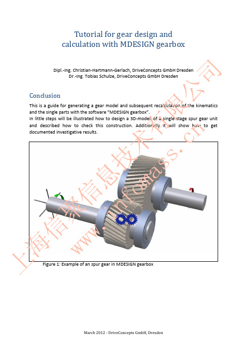
Gear design in MDESIGN gearbox
1. Index
1. 2. 3. 3.1.
Index ............................................................................................................................................ 2 Basic settings for calculation ....................................................................................................... 3 Modeling the gearbox .................................................................................................................. 6 Modeling the shafts ................................................................................................................. 6 Design of spur gears ............................................................................................................. 10 Modeling of bearings ............................................................................................................. 13 Modeling drive and output drive ............................................................................................ 15
ZIMM 螺旋千斤顶使用说明书
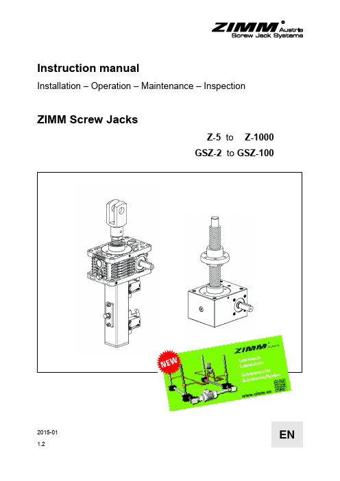
2015-01ENInstruction manualInstallation – Operation – Maintenance – InspectionZIMM Screw JacksZ-5 to Z-1000GSZ-2 to GSZ-100Translation of the original instruction manualPublisherZIMM Maschinenelemente GmbH + Co KGMillennium Park 36890 Lustenau/AustriaTel.: 0043 (0) 5577 806-0Fax: 0043 (0) 5577 806-8e-mail:************Internet: http://www.zimm.euAuthorZIMM Maschinenelemente GmbH + Co KGIssue date2015-01Version1.2Copyright© 2015 ZIMM Maschinenelemente GmbH + Co KGWe reserve the right to make changes to technical aspects and contentLegal noticesThe contents of this instruction manual must be kept confidential. It is intended only for use by company personnel.Reproduction or distribution and release of this instruction manual to third parties is prohibited. Offenders are liable to pay damages.The ZIMM Maschinenelemente GmbH + Co KG accepts no liability for damages arising from disregard of this instruction manual.ZIMM Screw Jack 1 About this documentContents1About this document (5)1.1Use of this instruction manual (5)1.2Symbols and identifying marks (5)2Safety (6)2.1Use for the intended purpose (6)2.2Duties of the operating company (6)3Scope of supply (7)4Description of the product (7)4.1Overview (7)4.2Rating plate (8)4.3Versions/variants (9)4.4Grease nipple (10)5Transport and storage (11)5.1Transport (11)5.2Storage (13)6Installation (14)6.1Installing screw jacks and bevel gear drives (15)6.2Fitting the couplings and connecting shafts (16)6.3Fitting the motor (18)6.4Connecting the electrical components (19)6.5Trial running (21)6.6Correcting the alignment (22)6.7Commissioning (23)6.8Running-in phase (23)7Operation and maintenance (24)7.1Inspection (24)7.2Lubrication (25)7.3Troubleshooting (31)8Decommissioning and recommissioning (33)9Repair and replacement (33)10Disposal (33)11Declaration of incorporation (34)1 About this document ZIMM Screw Jack 12Appendix: Inspection certificate (35)ZIMM Screw Jack 1 About this document1 About this document1.1 Use of this instruction manualThis instruction manual forms part of the ZIMM Screw Jack.→Before using the equipment read the instruction manual carefully.→Keep the instruction manual safe throughout the working life of theequipment.→Keep the instruction manual available to operating and maintenancepersonnel at all times.→Pass the instruction manual to any subsequent owner or user of theequipment.→Keep the instruction manual updated with any supplements issuedby the manufacturer.1.2 Symbols and identifying marksTab. 1:Symbols and identifying marks2 Safety ZIMM Screw Jack2 SafetyThe ZIMM Screw Jack has been produced to modern standards andrecognised safety regulations. Nevertheless hazards to life and limb ofthe users or third parties, or risks of damage to the ZIMM Screw Jackand other property may arise during use.→The ZIMM Screw Jack may be used only when it is in technicallygood condition and in compliance with the instruction manual.→Have any defects rectified without delay.→Do not perform any unauthorised modifications to the ZIMM ScrewJack.→Fit only original spare parts from ZIMM MaschinenelementeGmbH + Co KG.2.1 Use for the intended purposeThe ZIMM Screw Jack is suitable only for lifting, lowering, tilting andadvancing movements within the specified lifting capacity ranges.Responsibility to ensure correct use lies with the user.Screw jacks may be used only in the context and within the limitsspecified in our catalogues and brochures.To ensure compliance with the statutory limits for electromagneticcompatibility, the ZIMM Screw Jack may be used only within industrialapplications as defined in EN 50 081-2.Use for any purpose other than these intended purposes constitutesimproper use.If in doubt regarding the application of the ZIMM Screw Jack, consultZIMM Maschinenelemente GmbH + Co KG before proceeding.2.2 Duties of the operating company→Ensure that the ZIMM Screw Jack is operated and maintained onlyin compliance with this instruction manual and the rules andregulations applicable in the country of use.→Ensure that the personnel–responsible for operating the ZIMM Screw Jack are authorised,–are trained and qualified for the respective work,–have read and understood this instruction manual,–know the applicable safety rules and–wear personal safety equipment(safety gloves, safety helmet and safety shoes).ZIMM Screw Jack 3 Scope of supply3 Scope of supplyThe ZIMM Screw Jack is delivered in sufficiently secure packaging toprevent possible damage in transit.The scope of supply of the ZIMM Screw Jack includes the followingparts:•ZIMM Screw Jack•This instruction manual•Further parts as listed on the delivery note4 Description of the product4.1 OverviewFig. 1:Overview ZIMM Screw JackA to F: Faces of the ZIMM Screw Jack. For the Z series this is alsodisplayed on the casing.4 Description of the product ZIMM Screw Jack4.2 Rating plateFig. 2:Example of a rating plate1 ZIMM contact data2 Type designation3 Maximum static load gearbox(spindle etc. not considered) 4 Gear ratio 5 Rated speed6 max. speed7 Serial number8 Serial number asData Matrix CodeZIMM Screw Jack 4 Description of the product4.3Versions/variants1 Travelling nut2 Trapezoidal screwspindle TR3 Housing, Z series4 Drive shaft5 Spindle lubrication6 Limit switch7 Protective tube1 Ball screw spindle KGT2 Spindle lubrication3 Gearbox for ball screw drive KGT4 Description of the product ZIMM Screw Jack1 Electrical or opticalmonitoring2 Gearbox with integral safetynut SIFA3 Safety nut SIFA4 Electrical monitoring1 Housing, GSZ series4.4 Grease nippleS and R versions of the ZIMM Screw Jack are fitted with grease nipples,which allow simple and clean greasing of the spindle (apart from theflanged nut FM).ZIMM Screw Jack 5 Transport and storage5 Transport and storage5.1 Transport5 Transport and storage ZIMM Screw JackFig. 3: Examples for transporting the S version → When lifting with a crane, attach the slings to the lifting pointsprovided.→ When lifting the ZIMM Screw Jack for transport, spread the weightas evenly as possible across all the lifting points.Fig. 4: Examples for transporting the R versionS versionR versionZIMM Screw Jack 5 Transport and storage Securing for transportFor secure attachment, insert ring bolts or ring nuts to the gearbox.5.2 Storage→For other storage conditions and storage times:Consult ZIMM Maschinenelemente GmbH + Co KG.6 Installation ZIMM Screw Jack6 InstallationZIMM Screw Jack 6 Installation6.1 Installing screw jacks and bevel gear drives✓Ensure that the spindle of the ZIMM Screw Jack or on the ZIMMScrew Jack cannot be exposed to lateral loads.Fig. 6:Side forces on the spindle are not permissible.Fig. 7:Flatness, parallelism and angular accuracy6 Installation ZIMM Screw Jack1. Install the ZIMM Screw Jack and ensure straight alignment for thespindle attachments.2. Install the ZIMM Screw Jack with bolts, tighten the installation bolts.3. Install the spindle attachment with bolts, tighten the installationbolts.Fig. 8:Exceptions: Maximum inclination angle for self-aligningnuts (PM) is 3°, install all other nuts at right angles.Bevel gear driveThe T version can be turned round to change the direction of rotation.→Check the direction of rotation at installation.6.2 Fitting the couplings and connecting shafts✓The screw jacks to be connected must have been fully installed.✓The bevel gear drives must be installed where appropriate.1. Place the connecting shaft on the shaft extensions (ZIMM ScrewJack or bevel gear drives). Check that the gearboxes are correctlylevelled.ZIMM Screw Jack 6 Installation2. Secure the coupling half shells with attachment bolts tightened tothe following torques:Fig. 10:Installation of connecting shaftsPull the couplings KUZ (couplings without half shells) on to the shaftextensions. Tighten the set screw to the following torques:For increased secu rity the set screw can be secured using “mediumstrength” thread locking agent.6 Installation ZIMM Screw Jack6.3 Fitting the motor✓The screw jack must be installed.Fig. 11:Installing the motor1. Fit the motor flange (1) to the screw jack and bolt it into place.2. Fit the coupling halves (2) to the gearbox shaft and bolt them into place.3. Attach the coupling star (3).4. Pull the motor-side coupling halves (4) on to the motor shaft.5. Attach the motor (5) to the motor flange and bolt it into place.6. Fit the motor-side coupling halves (6) as follows:–Slide them on to the gearbox-side coupling halves, leaving1 mm axial play.–Tighten the securing bolt (7).–If the coupling halves cannot be slid on to the motor shaft:Adjust the position before step 5 and tighten them.ZIMM Screw Jack 6 Installation6.4 Connecting the electrical components6.4.1 Motor✓ The motor (if supplied) must be installed.1. Open the motor terminal box. The connection assignment is shownwithin the motor terminal box.2. Connect the motor in accordance with the circuit diagram.6.4.2Limit switchFig. 12: Fitting the plug connector on the limit switch1. Remove the protection element (1) from the limit switch.2. Remove the protection element (2) from the plug connector.3. Insert the plug connector (3) into the limit switch.4. Turn the screw (4) 90° clockwise.Connecting the limitswitch6 Installation ZIMM Screw Jack5. Connect the cable ends (5) in accordance with diagram (see Fig. 13).Fig. 13: Connection diagram for the limit switchBN BrownBK BlackBU Blue BK-WH Black-White GN-YE Green-YellowIf necessary the cable outlet can be turned through 180°.Fig. 14: Turning the cable outlet of the limit switch1. Loosen the screws (1) and unscrew them.2. Pull the limit switch (3) out of its bracket (2) and turn it through 180°.3. Insert the limit switch into the bracket (2) again.4. Refit the screws (1) and tighten them.Fig. 15: Adjustment of the limit switch1. Move the screw jack away from the limit switch trigger point.2. Loosen the screws (1).3. Adjust the limit switch by sliding it in the direction shown.4. Tighten the screws (1).Turning the cable outlet Adjusting the position ofthe limit switch±5mmZIMM Screw Jack 6 Installation6.5 Trial running✓The system must be installed and aligned.✓The spindle must be greased (for more information see section"7.2 Lubrication", page 25).→Run the screw jack over the complete travel in both directions.When doing this, comply with the following:–Run the screw jack slowly and carefully.–As far as possible, run it with no load or with only a small load.–Current consumption should be within the normal range, andshould be constant.Major fluctuations indicate alignment errors and stresses.–Monitor the temperature and avoid overheating, especiallywhere the travel is long and multiple runs are performedsuccessively.–Avoid overrunning the limit switch (optional).6 Installation ZIMM Screw Jack6.6 Correcting the alignmentIf necessary, the alignment can be corrected without much trouble.The spindle must be greased (for more information see section"7.2 Lubrication", page 25).S version1Fig. 16:Correctly aligned screw jack - S version1. Slacken the securing bolts on the gearbox casing and at the end ofthe spindle.2. Fully retract the jack (1).3. Tighten the securing bolts.4. Repeat the trial run (see section 6.5, page 21).R version213Fig. 17:Correctly aligned screw jack - R version1. Move the nut to the middle (1).2. Slacken the securing bolts on the gearbox casing and on the endbearing plate GLP.3. Extend the nut to just before the end bearing plate (2).ZIMM Screw Jack 6 Installation4. Tighten the securing bolts on the end bearing plate.5. Retract the nut to just before the gearbox (3).6. Tighten the securing bolts on the gearbox casing.7. Repeat the trial run (see section "6.5 Trial running", page 21).6.7 Commissioning✓The ZIMM Screw Jack together with its attachments must beinstalled and connected.✓The spindle must be greased (for more information see section"7.2 Lubrication", page 25).✓The trial run must have been completed successfully.1. Check all screw fastenings once again.2. Perform a trial run with operating load.When doing this, comply with the following:–Torque must be constant.–Current consumption must be constant.–Operating temperature must be within the normal range.–The limit switch (if fitted) or the end bearings must not beoverrun.3. Regrease the spindle after the first 2 operating hours at mediumload.6.8 Running-in phaseThe running-in phase of the gearbox and spindle lasts as a rule between20 and 50 operating hours. A higher torque and higher operatingtemperature must be expected during this period.The torque may be up to 50% higher during the running-in phase than insubsequent operation.7 Operation and maintenance ZIMM Screw Jack7 Operation and maintenance7.1 InspectionFor problem-free operation, the ZIMM Screw Jack must be inspectedregularly:•The first inspection should be no later than after 1 month•Further inspections should be performed at least annually1. Record the inspections, for a template see "Appendix: Inspectioncertificate", page 35.2. If necessary, perform Troubleshooting, see section 7.3, page 31.→If problems cannot be localised and rectified:Contact ZIMM Maschinenelemente GmbH + Co KG.7.1.1 Visual check✓Switch off the machine and secure it against switching on again.1. Check the greasing of the spindle, if necessary regrease and revisethe maintenance interval.2. Check the screws for the attachments and couplings/connectingshafts and if necessary retighten them.3. If a safety nut SIFA is fitted: Check wear in accordance with theFig. 18 (right hand picture) .–Make a note of dimension "A" and compare it with the set value.–Maximum permissible wear: 25% of the screw pitch.–If electronic monitoring is fitted, this check is not required.ZIMM Screw Jack7 Operation and maintenanceFig. 18:Safety trap nut SIFA: Dimension "A" for comparison whenchecking wear4. Visually check the coupling stars.5. Allow the machine to run, checking for the following:–Running without jerking and vibration–No excessive noise–Constant current consumption–Temperature rise within the -permissible range7.2 LubricationGood lubrication and use of the correct lubricants are critical for thecorrect operation and working life of the screw jack.Each screw jack application has different requirements, therefore thevalues specified in the following section are only recommendations.7.2.1 Lubricating screw jacksThe Z and GSZ series ZIMM Screw Jack are sealed and are filled withhigh-quality synthetic low-viscosity grease; from size 250 kN they arefilled with synthetic oil.Under normal operating conditions the gearbox is lubricated for life.7.2.2 Lubricating bevel gear drivesBevel gear drives are filled with synthetic oil and under normal operatingconditions lubricated for life.7 Operation and maintenance ZIMM Screw Jack7.2.3Greasing the spindle of a trapezoidal screw jack TR) The spindle of a trapezoidal screw jack must be greased regularly asrequired.Standard grease up to size 150 kN: Part no.: Castrol Tribol GR 4020/460-2 PD, 400 ml cartridgeStandard grease from size 250 kN:Part no.: Castrol Tribol GR 3020/1000-2 PD, 400 ml cartridgeQuantities for greasing new trapezoidal screw spindles TR:Intervals GreasesZIMM Screw Jack 7 Operation and maintenance✓ When changing the grease: The spindle must be clean.1. Remove the protective cap from the grease nipple.2. Press the nozzle of the grease gun against the grease nipple:– S version: Grease nipple on the gearbox casing– R version: Grease nipple on the travelling nut (optional)3. Filling with grease:– Providing personal safety is assured: Perform greasing whenextending, in order to ensure the best distribution of thegrease.– To do this, slowly extend the screw jack and apply strokes of thegrease gun. When doing so, make sure the correct quantity ofgrease is applied.Preconditions When extending7 Operation and maintenance ZIMM Screw JackWhen stationary–It is best to apply grease in several jack positions, to ensuregood distribution of grease.–S version: Apply only small quantities of grease at each jackposition, so that grease is not forced through the seals into thegearbox.–R version: If no grease nipple is fitted, apply the grease directlyto the spindle.ZIMM Screw Jack 7 Operation and maintenance7.2.4Greasing the ball screw drive KGT spindleStandard grease for ball screw drive KGT Part no.: Castrol Tribol GR 4747/220-2 HT, 400 ml cartridgeQuantity (indicative value):•1 ml per 1 cm spindle diameter.✓When changing the grease: The spindle must be clean.Intervals GreasePreconditions7 Operation and maintenance ZIMM Screw Jack1. Remove the protective cap from the grease nipple.2. Press the nozzle of the grease gun against the grease nipple:– S version: Grease nipple on the gearbox cover.– R version: Grease nipple on the travelling nut.3. Filling with grease:– Providing personal safety is assured: Perform greasing whenextending, in order to ensure the best distribution of the grease.– To do this, slowly extend the screw jack and apply strokes of thegrease gun. When doing so, make sure the correct quantity ofgrease is applied.– It is best to apply grease in several jack positions, to ensuregood distribution of grease.– S version: Apply only small quantities of grease at each jackposition, so that the grease is not forced through the seals intothe gearbox.When extending When stationaryZIMM Screw Jack7 Operation and maintenance7.3 TroubleshootingIf faults are evident, these should be localised according to specificcriteria, and rectified by application of appropriate actions. The followingtable offers start points as assistance for troubleshooting.7 Operation and maintenance ZIMM Screw JackZIMM Screw Jack 8 Decommissioning and recommissioning8Decommissioning and recommissioningAfter the ZIMM Screw Jack has been out of use for a long period: 1. Clean the spindle and2. Regrease the spindle, see section "7.2 Lubrication", page 25.9 Repair and replacement→ Contact ZIMM Maschinenelemente GmbH + Co KG.10 DisposalThe ZIMM Screw Jack satisfies the current standards and regulations for disposal of end of life equipment. It contains no poisonous substances which demand the taking of special precautions. → During disposal, ensure:– Compliance with regional laws and regulations for wastedisposal – Correct disposal and recycling should be entrusted to aprofessional disposal company The following materials will require disposal: • Lubricants (grease or oil in the gearbox, lubricating grease on the spindle)• Steel parts (coated with environmentally-friendly paints or coatings) • Anodised aluminium (parts)• Bronze/copper (bevel gear, nuts or windings on the motor) •Plastic parts (seals etc.)DecommissioningRecommissioning11 Declaration of incorporation ZIMM Screw Jack11 Declaration of incorporationZIMM Screw Jack12 Appendix: Inspection certificate12 Appendix: Inspection certificateTemplate for copying for inspections to section "7.1 Inspection",page 24.ZIMM Screw Jack (Serial number): ____________________________ZIMM Maschinenelemente GmbH + Co KG Millennium Park 36890 Lustenau / AustriaPhone: 0043 (0) 5577 806-0Fax: 0043 (0) 5577 806-8************www.zimm.eu。
弗兰德减速机制造标准
弗兰德减速机制造标准Flender gearbox is a well-known brand for manufacturing high-quality gears and gearboxes. 弗兰德减速机是一家以制造高品质齿轮和齿轮箱而闻名的品牌。
With a history dating back over a century, Flender has built a reputation for delivering reliable and efficient products. 具有100年历史的弗兰德已经建立起了可靠和高效产品的声誉。
Flender gearboxes are used in a wide range of industries, including mining, cement, and power generation. 弗兰德减速机在矿业、水泥和发电等各行各业都有广泛的应用。
Their gearboxes are known for their durability, performance, and precision engineering. 他们的减速机以耐用、高性能和精密工程而著称。
One of the key factors that make Flender gearboxes stand out is their adherence to strict manufacturing standards. 使弗兰德减速机脱颖而出的一个关键因素是他们严格遵守制造标准。
From design to production, Flender gears are manufactured with precision and attention to detail. 从设计到生产,弗兰德齿轮都精确制造,注重细节。
This ensures that each gearbox meets the highest quality standards and performs reliably in demanding industrial environments. 这确保每台减速机符合最高的质量标准,在苛刻的工业环境中可靠运行。
减速比单词
减速比单词单词:gear ratio(减速比)1. 定义与释义1.1词性:名词1.2释义:机械传动系统中输入轴转速与输出轴转速的比值,用于表示速度的降低比例关系。
1.3英文解释:The ratio of the rotational speed of the input shaft to that of the output shaft in a mechanical transmission system, used to represent the proportion of speed reduction.1.4相关词汇:- 同义词:reduction ratio- 派生词:geared(有齿轮的,与齿轮相关的)---2. 起源与背景2.1词源:“gear”来自古英语“gēr”,有装备、装置的意思,在机械领域逐渐发展出与齿轮相关的含义,“ratio”源于拉丁语,有比例、比率的意思,两者结合形成“gear ratio”这个术语,用于描述机械传动中的特定比率关系。
2.2趣闻:在汽车发展的早期,工程师们对齿轮比的研究和优化是提升汽车性能的关键。
不同的齿轮比设置可以让汽车适应不同的路况和驾驶需求。
例如,在爬坡时需要较大的减速比来提供更大的扭矩。
---3. 常用搭配与短语3.1短语:- optimal gear ratio:最佳减速比例句:The engineers are trying to find the optimal gear ratio for this new engine.翻译:工程师们正在努力为这个新发动机找到最佳减速比。
- high gear ratio:高减速比例句:A high gear ratio is required when towing heavy loads.翻译:拖重物时需要高减速比。
- adjustable gear ratio:可调减速比例句:This advanced transmission system has an adjustable gear ratio.翻译:这个先进的传动系统有一个可调减速比。
轮机英语翻译课文
LESSON 1Diesel enginesThe majority of ships around the world continue to be powered exclusively by diesel engines.世界范围内大多数船舶都是采用柴油机作为动力。
The predominance of diesel engines has come from improved engine efficiencies and designs compared to other forms of propulsion such as steam or gas turbines.与蒸汽机、燃气轮机等形式的动力装置相比,无论是效率上的提高,还是设计上的进步,柴油机都体现出了一定的优势。
Many combinations and configurations of diesel engine power plant exist. All provide the energy to do the work of moving the ship using diesel engines.存在有很多种联合形式及结构形式的柴油机动力装置,他们都能够利用柴油机为船舶提供推动力。
Slow speed diesel engines 低速柴油机Slow speed diesel engines are large, especially tall, and heavy and operate on the two-stroke cycle.低速柴油机是体积较大、缸体较长、机身较重的二冲程柴油机。
These are the largest diesel engines ever built. Engine powers up to 100 000kw are available from a single engine.它们是已建造过的最大型的柴油机,它们的单机可用功率可达100000 kw。
减速器论文中英文对照资料外文翻译文献

减速器论文中英文对照资料外文翻译文献What is a Gearbox?A XXX.1.The n of a Gearbox1) The gearbox ces the speed while increasing the output torque。
The torque output。
is the motor output multiplied by the n。
but it should not exceed the XXX.2) The gearbox also ces the inertia of the load。
which decreases by the square of the n。
Most motors have an inertia value that can be XXX.2.Types of GearboxesCommon gearboxes include bevel gear cers (including parallel-axis bevel gear cers。
worm gear cers。
and cone gear cers)。
ary gear cers。
cycloid cers。
worm gear cers。
XXX.mon Gearboxes1) The main feature of the worm gear cer is its reverse self-locking n。
which can achieve a large n。
The input and output shafts are not on the same axis or in the same plane。
However。
it generally has a large volume。
low n efficiency。
and low n.2) XXX and power。
It has a small size and high n。
- 1、下载文档前请自行甄别文档内容的完整性,平台不提供额外的编辑、内容补充、找答案等附加服务。
- 2、"仅部分预览"的文档,不可在线预览部分如存在完整性等问题,可反馈申请退款(可完整预览的文档不适用该条件!)。
- 3、如文档侵犯您的权益,请联系客服反馈,我们会尽快为您处理(人工客服工作时间:9:00-18:30)。
1Gear & GearboxMotion drivingChange speed ratioReverse orientation Prepared by: Wilson Wang2018-07-30•Part 1: Classification of Gears •Part 2: Common Gearbox•Part 3: Material selection•Part 4: Measurement &Inspection •Part 5: Common Problems •Questions•Spur •Helical •Worm •Bevel •CrownSpur Gear•General Characteristic:–Majority of gears are spur.–Relatively easy to designand make.–Parallel shaft.–High efficiency.–Can back drive.Spur Gear -Internal •GeneralCharacteristic :–Similar performance tonormal spur–Results in compactdrive geometry.–Typical model : Epicycle/ Planetary gears.Spur Gear -Rack •GeneralCharacteristic:–Transit rotary motion tolinear motion.–Proportional constantvelocity.–Material select on POM(stiff); Nylon (Tough)Helical Gear•General Characteristic :–Single Helical have similarproperties to spur.–Drive results in axial thrust.–Smoother / quieter for same size / spec.–Can run high speed, highertorque / life capabilities forsame size as spur.Worm Gear•General Characteristic :–Offset shafts at 90Degree.–Very high ratiospossible in singlestage.–Low efficiency athigher ratios and lowspeed.–Cannot drive back.Bevel Gear•GeneralCharacteristic:–Drive transmissionthrough 90 degree.–Only low ratiosused. (4:1 and less)–Not used on highduty high speedapplication.Crown Gear•Battery operated motor gearbox •Mechanical Driven gearbox (Non Battery type)•Wind up type•Pull back type•Friction type•Press and go type•Battery operated gearbox•Motion Driven by Wind up mechanism•Motion Driven by Pullbackmechanism•Motion Driven by Press and Gorelease mechanism•Motion Driven by Friction Push (Flywheel) mechanism•Mechanical Driven (Non Battery type)Type ofCommon ApplicationMechanismWind up Walking, Car running, ClimbingPull back Car runningPress and Go Car runningFriction Car running•Acetal (POM)•Nylon (PA)•HytrelComparison on Material type of GearsRemarks: Best 1 to Good 3, Easy 1 to Difficult 3.•Gearbox key characteristics–Target specification(Key parameters)Setting the target before start the design1) Dimension2) Output Torque3) Noise Requirement4) Life cycle5) Current draw1Aesthetics1.1Aesthetics insepction(注件不满,齿崩,缺齿,飞边,翘曲、气泡、凹陷等)Visual/CCD2Main Dimension2.1Dimension 1:齿顶(齿根)圆直径二次元/卡尺(偶数齿)2.2Dimension 2:孔径/轴径二次元/塞规2.3Dimension 3:齿厚齿轮卡尺2.4Dimension 4:齿宽卡尺2.5Dimension 5:偏心度*啮合机3Main Gear Precision3.1Precision 1:齿轮齿形齿向误差齿形齿筋测量仪3.2Precision 2:齿轮径向跳动误差齿形齿筋测量仪或啮合机(master gear)3.3Precision 3:齿轮切向综合误差啮合机(master gear)3.4Precision 4:齿轮径向综合误差啮合机(master gear)4Reliability and function4.1play function after assembly by hand4.2gear noise db meter4.3product life homemade fixture Main inspection pointsMain Equipment齿形齿筋测量仪Main Equipment啮合机(master gear)Basic parameterM=d/zBasic parameterBasic parameterBasic parameterBasic parameter•General problems1.Noise2.Torque3.Speed4.Gear break5.Life6.Aesthetics注件不满,齿崩,缺齿,飞边,翘曲、气泡、凹陷等Points to be considered on gearbox performanceTroublePossible faultFunctionLife NoiseCurrent Torque Speed Gear break 1Alignment of centerdistanceToo loosesYes X Yes X Yes Yes Too tight Yes Yes Yes YesYes Yes 2Clutch force adjustmentToo weakX X Yes X X X Too high XX X X YesX 3Gear damagelittleYes Yes X X X Yes largeYesYesYesYesYesYes4Over loadingYesYes Yes Yes X Yes 5LubricationExcessX Yes X Yes X X Not enoughYes Yes Yes Yes Yes Yes 6Interference of gearYesYesYesYesYesYes•How to achieve an Ideal Gearbox?–Design–Tool fabrication–Injection–Inspection•Key issue: Noise and vibrationQ:How to reduce the source of noise &vibration?a.Soft material as a motor pinion, because thehigher speed over there. (reduce motor noisefirst)b.High concentricity between Shaft and gearc.Proper lubricantd.Less speed ratio between level 1 and level 2 geare.Shape of gear toothf.Center distance ,a=m(z1+z2)/2+0.3mg.Unsealed gearbox•Key issue: LubricationQ : How much viscosity is suitable?Lubrication advantage is reduce friction and noise, but the side effect is tocause the current draw get higher.Case study -1•Design toleranceCase study -1•Design Tolerance–Case is no room for make the gear larger andstrong when the torque requirement for theproduct increase 10% during the EP stage.•Actions–Redesign the gearbox and rebuild all the tooling,lost the money and project delay.•Solution for future–Reserve design allowance: reserve the room forfurther development around 30% to 50% atDFMEA.Case Study –2•Material selectionBackground:Incorrect shaftmaterial(Nylon) wasused due tounderestimated thetorque there. The gearfailed torque test ,andthen change to POMwith tightenedassembly for solution.•Design based on torqueThanks!。