模拟心电信号发生器SKX-2000
SK 2000 无线电发射机使用说明书

ContentsImportant safety instructions (2)The SK 2000 bodypack transmitter (3)Areas of application (3)The frequency bank system (4)Delivery includes (5)Product overview (6)Overview of the SK 2000 bodypack transmitter (6)Overview of the displays (7)Putting the bodypack transmitter into operation (8)Inserting the batteries/accupack (8)Charging the accupack (8)Connecting the microphone cable/instrument cable (9)Attaching the bodypack transmitter to clothing (10)Using the bodypack transmitter (11)Switching the bodypack transmitter on/off (11)Deactivating the lock mode temporarily (12)Muting the audio signal or deactivating the RF signal (13)Selecting a standard display (15)Using the operating menu (16)The buttons (16)Overview of the operating menu (16)Working with the operating menu (18)Synchronizing the bodypack transmitter with a receiver (20)Synchronizing the bodypack transmitter with the receiver – individual operation (20)Synchronizing bodypack transmitters with receivers–multi-channel operation (20)Cleaning the bodypack transmitter (21)If a problem occurs ... (21)Specifications (23)For further information, visit the SK2000 product page onour website at .1Important safety instructionsImportant safety instructions•Read this instruction manual.•Keep this instruction manual. Always include this instruction manual when passing the product on to third parties.•Heed all warnings and follow all instructions.•Use only a cloth for cleaning the product.•Do not place the product near any heat sources such as radiators, stoves, or other devices (including amplifiers) that produce heat.•Only use attachments/accessories specified by Sennheiser.•Refer all servicing to qualified service personnel.Servicing is required if the product has been damaged in any way, liquid has been spilled, objects have fallen inside, the product has been exposed to rain or moisture, does not operate properly or has been dropped.•WARNING: To reduce the risk of short circuits, do not use the product near water and do not expose it to rain or moisture.Intended useIntended use of the SK 2000 bodypack transmitter includes:•having read this instruction manual, especially the chapter “Important safety instructions”,•using the product within the operating conditions and limitations described in this instruction manual.“Improper use” means using the product other than as described in these instructions, or under operating conditions which differ from those described herein.2The SK 2000 bodypack transmitterThe SK 2000 bodypack transmitterThis bodypack transmitter is part of the 2000 series. With this series, Sennheiser offers high-quality state-of-the-art RF transmission systems with a high level of operational reliability and ease of use. Transmitters and receivers permit wireless transmission with studio-quality sound. Features of the 2000 series:•Optimized PLL synthesizer and microprocessor technology•HDX noise reduction system•Pilot tone squelch control•True diversity technology•Switching bandwidth of up to 75 MHz•Increased immunity to intermodulation and interferences in multi-channel operationAreas of applicationThe bodypack transmitter can be combined with the EM2000 or EM 2050 rack-mount receiver. The receivers are available in the same UHF frequency ranges and are equipped with the same frequency bank system with factory-preset frequencies. An advantage of the factory-preset frequencies is that:• a transmission system is ready for immediate use after switch-on,•several transmission systems can be operated simultaneously on the preset frequencies without causing intermodulation interference.3The SK 2000 bodypack transmitterOverview of the microphones and instrument cables:The frequency bank systemThe bodypack transmitter is available in 6 UHF frequency ranges with up to 3,000 transmission frequencies per frequency range:Each frequency range (Aw–Ew, Gw, GBw) offers 26 frequency banks with up to 64 channels each:4Delivery includes Each of the channels in the frequency banks “1” to “20” has been factory-preset to a fixed frequency (frequency preset). The factory-preset frequencies within one frequency bank are intermodulation-free. These frequencies cannot be changed.For an overview of the frequency presets, please refer to the supplied frequency information sheet. Updated versions of the frequency informa-tion sheet can be downloaded from the corresponding product page on our website at .The frequency banks “U1” to “U6” allow you to freely select and store transmission frequencies. It might be that these transmission frequencies are not intermodulation-free.Delivery includesThe packaging contains the following items:1 SK 2000 bodypack transmitter2 AA size batteries, 1.5 V1 instruction manual1 frequency information sheet1 supplement “Framework requirements and restrictions on the use of radio microphones”5Product overviewProduct overviewOverview of the SK 2000 bodypack transmitter³Microphone/instrument input (MIC/LINE), 3-pole special audiosocket, lockable·MUTE switch»Antenna¿Operation and battery status indicator, red LED:lit = ONflashing = LOW BATT´Audio overmodulation indicator, yellow LED:lit = AF PEAK ²Charging contacts¶SET buttonºUP/DOWN button ̆/̄¾Battery compartmentµBattery compartment cover (metal)¸Battery compartment catches ¹Infra-red interfaceƸON/OFF button(serves as the ESC (cancel) key in the operating menu)ƹDisplay panel, backlit in orange6Product overviewOverview of the displaysAfter switch-on, the bodypack transmitter displays the standard display “Frequency/Name”. For further illustrations and examples of the different standard displays, refer to page15. The display backlighting is automati-cally reduced after approx. 20 seconds.8Putting the bodypack transmitter into operationPutting the bodypack transmitter into operationInserting the batteries/accupackFor powering the bodypack transmitter, you can either use two 1.5 V AA size batteries or the rechargeable Sennheiser BA 2015 accupack or the DC 2 power adapter (accessories, visit ).̈Open the battery compartment by pushing the two catches ¸ in the direction of the arrows and open the cover µ.̈Insert the two batteries or the accupack as shown above. Please observe correct polarity when inserting the batteries/accupack.̈Close the battery compartment.The battery compartment cover µ locks into place with an audible click.Charging the accupackTo charge the BA 2015 accupack (accessory, visit )installed in the bodypack transmitter:̈Insert the bodypack transmitter into the L 2015 charger (accessory,visit ).2015Putting the bodypack transmitter into operationConnecting the microphone cable/instrument cable The audio input is designed for the connection of both condenser micro-phones and instruments (e.g. guitars). DC powering of the condenser microphones is via the MIC/LINE socket³ (3-pole special audio socket).̈Use one of the recommended Sennheiser microphones or the CI1-4 instrument cable (see page3).̈Connect the 3-pin special audio connectorƺ from the Sennheiser microphone or instrument cable to the MIC/LINE socket³.̈ringƻ.̈Via the operating menu (“Sensitivity” menu item), adjust the sensi-tivity of the microphone/line input.910Putting the bodypack transmitter into operationAttaching the bodypack transmitter to clothingYou can use bodypack pouch or the belt clip ƽ to attach the bodypack transmitter to clothing (e.g. belt, waistband).The belt clip is detachable so that you can also attach the transmitter with the antenna pointing downwards. To do so, withdraw the belt clip ƽ from its fixing points and attach it the other way round.The belt clip ƽ is secured so that it cannot slide out of its fixing points accidentally.To detach the belt clip:̈Lift one side of the belt clip as shown.̈̈11Using the bodypack transmitterUsing the bodypack transmitterTo establish a transmission link, proceed as follows:1.Switch the bodypack transmitter on (see next section).2.Switch the receiver on (see the instruction manual of the receiver).The transmission link is established and the display backlighting of the receiver changes from red to orange.If you cannot establish a transmission link between transmitter and receiver, read the chapter “Synchronizing the bodypack transmitter with a receiver” on page 20.̈To switch the bodypack transmitter on (online operation):To switch the bodypack transmitter on and to deactivate the RF signal on switch-on (offline operation):̈Briefly press the ON /OFF button Ƹ.The “Frequency/Name ” standard display appears on thedisplay panel. The red ON LED ¿ lights up and the transmis-sion icon ብ is displayed. The bodypack transmitter transmitsan RF signal.̈Keep the ON /OFF button Ƹ pressed until “RF Mute Off?”appears on the display panel.12Using the bodypack transmitterTo activate the RF signal :To switch the bodypack transmitter off :̈If necessary, deactivate the lock mode (see next chapter).Deactivating the lock mode temporarilyYou can activate or deactivate the automatic lock mode via the “Auto Lock ” menu item. If the lock mode is activated, you have to temporarily deactivate it in order to be able to operate the bodypack transmitter:̈Press the UP/DOWN button ̆/̄.“RF Mute On?” appears on the display panel.̈Press the SET button.The transmission frequency is displayed but the bodypacktransmitter does not transmit an RF signal. The transmissionicon ብ is not displayed. When the pilot tone function isactivated on both bodypack transmitter and receiver,“RF Mute ” (backlit in red) appears alternately with the stan-dard display on the receiver’s display panel.̈Press the ON /OFF button.“RF Mute On?” appears on the display panel.̈Press the UP/DOWN button ̆/̄.“RF Mute Off?” appears on the display panel.̈Press the SET button.The RF signal is activated and the transmission icon ብ is dis-played again.̈Keep the ON /OFF button Ƹ pressed until “OFF ” appears on the display panel. The red ON LED ¿ goes off and the displaypanel turns off.ON /OFF button Ƹ will13Using the bodypack transmitterThe lock mode icon ቦ flashes prior to the lock mode being activated again.̈From the “Mute Mode ” menu item, select the desired setting. ̈Exit the operating menu.̈Slide the MUTE switch · to the left, to the position MUTE .The bodypack transmitter reacts as indicated in the table.̈Press the SET button or the ON /OFF button.“Locked ” appears on the display panel.̈Press the UP/DOWN button ̆/̄.“Unlock?” appears on the display panel.̈Press the SET button.The lock mode is temporarily deactivated.–When you are in the operating menu, the lock moderemains deactivated until you exit the operating menu.–When one of the standard displays is shown, the lock modeis automatically activated after 10 seconds.14Using the bodypack transmitterThe current state of the muting function or the RF signal is displayed on the display panel of the bodypack transmitter.the pilot tone function is activated on both bodypack trans-mitter and receiverand, in addition,•this display has been activated via the “Warnings ” menu item on the receiver (see the instruction manual of the receiver).Transmitter’s display panel:“MUTE ” ቨ is displayed Receiver’s display panel:TX Mute ” is displayed **only when activated on the receiver (see above)Transmitter’s display panel:“MUTE ” ቨ is not displayed Receiver’s display panel:“TX Mute ” is not displayed Transmitter’s display panel:Transmission icon ብ is not displayed, “MUTE ” ቨis displayed Receiver’s display panel:“RF Mute ” is displayed **only when activated on the receiver (see above)Transmitter’s display panel:Transmission icon ብ is displayed Receiver’s display panel:“RF Mute ” is not displayed15Using the bodypack transmitterSelecting a standard display11.Using the ON /OFF button, you can also activate/deactivate the RF signal during operation. To do so, briefly press the ON /OFF button and proceed as described on page 12.̈Press the UP/DOWN button ̆/̄ to select a standarddisplay:Using the operating menuUsing the operating menu The buttonsOverview of the operating menu16Using the operating menuMain menu “Menu”Sensitivity Adjusts the sensitivity “AF”Frequency Preset Sets the frequency bank and the channelName Enters a freely selectable nameAuto Lock Activates/deactivates the automatic lock mode Advanced Calls up the extended menu “Advanced Menu”Exit Exits the operating menu and returns to the currentstandard displayExtended menu “Advanced Menu”Tune Sets the transmission frequencies for the frequencybanks “U1” to “U6”Sets the channel and the transmission frequency forthe frequency banks “U1” to “U6”Mute Mode Sets the mode for the MUTE switch·RF Power Adjusts the transmission powerCable Emulation Emulates guitar cable capacitiesPilot Tone Activates/deactivates the pilot tone transmission LCD Contrast Adjusts the contrast of the display panelReset Resets the settings made in the operating menu Software Revision Displays the current software revisionExit Exits the extended menu “Advanced Menu” andreturns to the main menu1718Using the operating menuWorking with the operating menuBy way of example of the “Sensitivity ” menu, this section describes how to use the operating menu.Changing from a standard display to the operating menu Selecting a menu itemChanging and storing settings̈Press the SET button.The current standard display is replaced by the main menu.The last called up menu item is displayed.̈Press the UP/DOWN button ̆/̄ to change to the “Sensi-tivity ” menu item.The current setting of the selected menu item is displayed:̈Press the SET button to call up the menu item.̈Press the UP/DOWN button ̆/̄ to adjust the input sensi-tivity.̈Press the SET button to store the setting.19Using the operating menuCanceling an entryTo subsequently return to the last edited menu item:Exiting a menu itemTo directly return to the current standard display:̈Press the ON /OFF button to cancel the entry.The current standard display appears on the display panel.̈Press the SET button repeatedly until the last edited menuitem appears.̈Change to the “Exit ” menu item.̈You return to the next higher menu level or you exit the oper-ating menu and return to the current standard display.̈Press the ON /OFF button.20Synchronizing the bodypack transmitter with a receiverSynchronizing the bodypack transmitter with a receiverWhen synchronizing the bodypack transmitter with a receiver, please observe the following:Synchronizing the bodypack transmitter with the receiver – individual operationUpon delivery, the bodypack transmitter and the receiver are synchro-nized with each other. However, if you cannot establish a transmission link between bodypack transmitter and receiver, you have to synchronize the channels of the devices.For information on automatic synchronization of the bodypack trans-Alternatively, you can set the channel on the bodypack transmitter manually:̈Make sure that you set the bodypack transmitter to the same frequency bank and the same channel as the receiver.If you still cannot establish a transmission link, refer to the chapter “If a problem occurs ...” on page 21.Synchronizing bodypack transmitters withreceivers – multi-channel operationCombined with 2000 series receivers, 2000 series bodypack transmitters can form transmission links that can be used in multi-channel systems. For information on automatic synchronization of bodypack transmitters with receivers (multi-channel operation), refer to the instruction manual of your receiver.For more information on multi-channel operation, visit the SK 2000product at .̈Make sure that the desired frequencies are listed in the enclosed frequency information sheet.̈Make sure that the desired frequencies are approved and legal in your country and, if necessary, apply for an operating license.21Cleaning the bodypack transmitterCleaning the bodypack transmitter̈Use a cloth to clean the bodypack transmitter from time to time.If a problem occurs ...CAUTION !Liquids can damage the electronics of the bodypacktransmitter!Liquids entering the housing of the device can cause ashort-circuit and damage the electronics.̈Keep all liquids away from the bodypack transmitter. Bodypack transmitter cannot be operated, “Locked ” appears onthe display panelLock mode is activatedDeactivate the lock mode(see page 12).No operationindicationBatteries are flat or accupack is flat Replace the batteries or recharge the accupack (see page 8).No RF signal at thereceiver Bodypack trans-mitter and receiverare not on thesame channel Set the bodypack trans-mitter to the same channel as the receiver.Synchronize the bodypacktransmitter with thereceiver (see page 20).Bodypack trans-mitter is out of rangeReduce the distancebetween bodypacktransmitter and receivingantenna.Increase the transmissionpower (“RF Power ” menuitem).RF signal isdeactivated(“RF Mute “)Activate the RF signal (see page 13).22If a problem occurs ...If a problem occurs that is not listed in the above table or if the problem cannot be solved with the proposed solutions, please contact your local Sennheiser partner for assistance.To find a Sennheiser partner in your country, search at under “Service & Support”.RF signal available,no audio signal,“MUTE ” appears onthe display panel Bodypack trans-mitter is muted (MUTE )Cancel the muting (see page 13).Receiver’s squelchthreshold isadjusted too highReduce the squelch threshold setting on the receiver.Bodypack trans-mitter doesn’ttransmit a pilottone Activate or deactivate the pilot tone transmission (“Pilot Tone ” menu item).Audio signal has ahigh level of back-ground noise or isdistorted Bodypack trans-mitter’s sensitivity is adjusted too low/too highAdjust the input sensitivity (“Sensitivity ” menu item).23Specifications SpecificationsRF characteristicsAF characteristicsModulationwideband FM Frequency ranges516–558, 558–626, 626–698, 718–790, 790–865, 606–678MHz (Aw to Dw, Gw, GBw, see page 4)Transmission frequenciesup to 3,000 frequencies,tuneable in steps of 25 kHz 20 frequency banks, each with up to 64factory-preset channels 6 frequency banks, each with up to 64user programmable channels Switching bandwidthup to 75MHz Nominal/peak deviation±24kHz/±48kHz Frequency stability≤ ±15ppm RF output power at 50Ωswitchable:typ. 10mW (Low)typ. 30mW (Standard)typ. 50mW (High)Pilot tone squelchcan be switched off Compander systemSennheiser HDX AF frequency responsemicrophone: 80–18,000Hz line: 25–18,000Hz Signal-to-noise ratio(1 mV, peak deviation)≥ 120dBA THD≤ 0.9%Max. input voltage(microphone/line)3V rms Input impedancemicrophone: 40k Ω, unbalanced line: 1M ΩAdjustment range of inputsensitivity 60dB, adjustable in 3-dB steps24SpecificationsOverall deviceIn compliance withApproved byConnector assignmentTemperature range– 10°C to + 55°C Power supply2 AA size batteries, 1.5 V or BA 2015 accupack Nominal voltage2.4VPower consumption:•at nominal voltage•with switched-offtransmittertyp. 185mA (30mW)≤ 25μA Operating timetyp. 8hrs Dimensionsapprox. 82mm x 64mm x 24mm Weight (incl. batteries)approx. 160g Europe:EMC EN 301489-1/-9Radio EN 300422-1/-2Safety EN 60065EN 62311 (SAR)Canada:Industry Canada RSS-123IC: 2099A-SK2000limited to 698 MHzUSA:FCC-Part 74FCC-ID: DMOSK2000limited to 698 MHz。
SKX-2000G+ 心电信号模拟仪 操作手册说明书
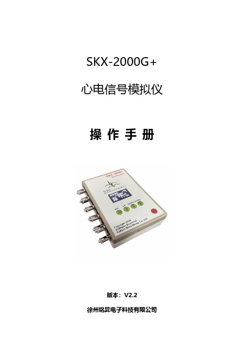
SKX-2000G+心电信号模拟仪操作手册版本:V2.2徐州铭昇电子科技有限公司目录第一章仪器特点注意事项 (3)功能特点 (3)模拟仪的待机工作时间 (3)注意事项 (4)第二章仪器连接说明 (5)第三章软件界面说明 (6)第四章按键说明 (7)第五章模拟仪波形类型及参数介绍 (10)第六章波形详细介绍及检测内容 (13)第七章售后服务 (25)第一章仪器特点注意事项SKX-2000G+心电信号模拟仪是徐州铭昇公司专业开发的一款用于心电类产品开发及检测的信号模拟工具,由于其可以产生多种人体心电级的信号,是开发心电类产品的必备首选工具,其具有宽广的信号幅度范围,可以模拟出多种幅度、频率的心电类信号,是开发心电类产品的重要工具。
本模拟仪同时具有心电类产品的检测功能,用于检测心电类产品的各项参数指标是否可以到达国家标准要求,后续章节将详细介绍检测过程中的各种信号的设置等。
功能特点:1、采用10个万用心电接头,可以方便快捷连接监护仪、心电图机等心电类产品导联线;2、12导联同步心电信号输出,输出不同的12导心电波形;3、内置18650大容量锂电池,电源管理模块,在使用过程中保证电源稳定、低干扰的输出。
选配标准的micro usb通用接口电源充电器;4、采用菜单式操作,参数更改简单、方便、快捷,方便用户设置;5、采用OLED显示屏,显示菜单内容;6、简单的按键操作,菜单管理,使用简单方便;7、内置中英文的波形设置说明,轻松了解波形设置及参数选择。
模拟仪的待机工作时间:1、当电量显示为0%的时候,开机状态下模拟仪可以再工作1分钟后自动关机,如果选择任意按键,则定时关机进行延时,直至1分钟内无按键处理后自动关机;2、当电量显示为10%的时候,开机状态下模拟仪可以再工作5分钟后自动关机,如果选择任意按键,则定时关机进行延时,直至5分钟内无按键处理后自动关机;3、当电量低于0%时模拟仪,将不能再次开机;注意事项:1、SKX-2000G+心电信号模拟仪可以对心电类设备进行定标,定标导联仅限于II,即RA-LL端输出的信号幅度,连接心电设备的RA 导联至模拟仪的RA端,LL导联至模拟仪的LL端,则心电设备采集的信号满足软件中设置的信号幅度范围0.1mV-4mV;2、心电波形中的波形幅度是0.5mV,1mV,2mV,3种固定幅度可选择更改;3、如果定标其他导联时,请按照下列方法进行定标:1)I导联定标:请将导联线RA连接至模拟仪RA端,导联线LA 连接至模拟仪LL端,此时心电设备采集的信号就是I导联的定标信号;2)C导联定标:请将RA、LA、LL并联后连接至模拟仪RA端,C1或者其他胸导联连接至模拟仪LL端,此时采集到的C1(或者其他胸导联)则为标准的定标信号;4、关于偏置电压的检测方法,当测试正向偏置时,请选择正弦波形,并连接心电设备的RA至模拟仪的LL端,心电设备的LL至模拟仪的RA端进行正偏置电压测试;当测试负偏置电压时,请选择正弦波形,并连接心电设备的RA至模拟仪的RA端,心电设备的LL至模拟仪的LL端进行负偏置电压测试;5、当连续一分钟内没有按键操作时,屏幕将会自动关闭,按任一按键后屏幕恢复显示,在屏幕关闭后,指示灯开始工作,每5秒闪烁一次;屏幕恢复显示后,指示灯停止闪烁。
SK-2000硬件使用手册之色谱仪操作指南

③ 接通仪器的总电源(图 4-3 SK-3Q04 分析单元前面板的虚线框所示),SK-3Q04 测控系统进入控制
状态( 注意:开机进入显示画面约需要 2-3 分钟),仪器就按固定的程序工作,并进入主控制 界面,见图 6-1。用 TFT 显示屏下方的“状态”监视检查机内色谱柱温度、样品气压力、载气流量 等各参数是否符合所希望的值(用触摸屏的操作笔连按二次触摸屏的“状态”键),仪器为了防止误 操作,只有连续按二次触摸屏的有关键方起作用,见图 6-2。
注意:SK-3Q04 氢焰色谱仪属于快速色谱,保留记录仪&积分仪输出方式,推
荐使用电子记录方式。神开公司特地开发无纸记录方式,提供相应软件支持。传统的记
录仪使用机械传动方式,在快速信号响应时容易不足或冲过头,造成较大的信号失真,
在快速分析时请谨慎使用。
2.工作原理 SK-3Q04 氢焰色谱仪是以气相色谱原理制作的仪器,它可以在线取得泥浆脱气器脱出的天然气
9
3
8
47
56
——预 切,分析
…… 充样,反
吹
Байду номын сангаас
总烃FID 组分FID
样品 输入
电
电
磁
磁
阀
阀
2
电磁阀3
1
驱动气 缸
空气压力 表
VMS
氢气压力表
图 4-9 SK-3Q04 分析单元气路控制图
SK-3Q04 氢焰色谱仪操作指南
5.安装 每台 SK-3Q04 氢焰色谱仪应参照图 5-1 要求连接。
脱
泵 PUMP
图 6-1 SK-3Q04 显示的控制主界面
状态 二FID 火点燃显示
SIGLENT SDS2000X数字显示仪快速用户指南说明书
SDS2000X 数字示波器快速指南SDS2000X 快速指南-I深圳市鼎阳科技有限公司版权所有。
本公司产品受已获准及尚在审批的中华人民共和国专利的保护。
本公司保留改变规格及价格的权利。
本手册提供的信息取代以往出版的所有资料。
未经本公司同意,不得以任何形式或手段复制、摘抄、翻译本手册的内容。
注:SIGLENT 是深圳市鼎阳科技有限公司的注册商标。
了解下列安全性预防措施,以避免人身伤害,并防止本产品或与其相连接的任何其它产品受到损坏。
为了避免可能发生的危险,请务必按照规定使用本产品。
使用适当的电源线--只允许使用所在国家认可的本产品专用电源线。
将产品接地--本产品通过电源电缆的保护接地线接地。
为了防止电击,在连接本产品的任何输入或输出端之前,请务必将本产品正确接地。
正确连接信号线--信号线与地电势相同,请勿将地线连至高电压。
查看所有终端额定值--为了避免火灾或电击,请查看本产品的所有额定值和标记说明。
请在连接产品前阅读产品手册,以便了解有关额定值的详细信息。
使用合适的过压保护--确保没有过电压(如由雷电造成的电压)到达该产品,否则可能导致操作人员遭受电击。
防静电保护--静电会造成仪器损坏,应尽可能在防静电区进行测试。
连接电缆到仪器前,应将其内外导体短暂接地以释放静电。
保持良好的通风 --通风不当会引起仪器温度升高,进而引起仪器损坏。
使用时应保持良好的通风,定期检查通风口和风扇。
避免电路外露 --电源接通后,请勿接触外露的接头和元件。
请勿开盖操作--请勿在仪器机箱打开时运行本产品。
使用合适的保险丝 --只允许使用本产品指定规格的保险丝。
请勿在潮湿或易燃易爆的环境下操作注意搬运安全 --为避免仪器在搬运时滑落,造成仪器面板上的按键、旋钮或接口等部件损坏,请在搬运仪器的过程中注意安全。
怀疑产品出故障时,请勿操作 --如怀疑产品有故障,请联系SIGLENT授权的维修人员进行检测。
任何对于本产品的维护、调整或零件更换必须由SIGLENT授权的维修人员执行。
毕业设计_心电检测仪

摘要本课题主要设计一个基于Atmega16的家用心电监测仪的研究设计。
根据人体心电信号的特征,设计心电信号采集系统,完成实时心电监测的功能。
本系统通过硬件电路实现了对心电信号实时的采集和处理,并将模拟的心电信号转换成数字信号送入主控单元,从而实现了心电信息的实时显示、存储、打印、报警等功能。
本设计选用具有低功耗的16位单片机Atmega16作为中央处理系统,通过心电传感器,从人体连续取得心电信号,经过专门的信号处理电路进行处理后送入中央处理系统,中央处理系统通过分析、处理,检测出病人的心电信号,并与正常的心电信号比较,对采集的心电信号进行实时分析、检测及记录,并选取大容量Flash存储器对采集处理后的心电信号进行存储。
同时,监测仪带有液晶显示器,能实时显示所检测的心电信号。
当病人出现紧急的心电症状时,其特有的报警功能可以及时的发出报警,便于及时的对病人进行救治。
该系统还可以打印出心电波形供医务人员分析病情时参考,及时准确的采取治疗措施,制定治疗方案。
该监测仪能长期、连续、可靠、稳定的工作,同时还具有体积小、存储容量大、功耗低、实时显示等特点,便于随身携带,使用方便,操作简单。
关键词心电监测心电监测仪心电传感器信号处理电路Title: The design of household ECG monitorAbstractThe topics mainly based Atmega16 household ECG monitor research and design. According to the characteristics of the human ECG, design ECG acquisition system,in real-time ECG monitoring function.This system has realized through the hardware circuit to heart signal real-time gathering and processing, and will simulate the heart signal transforms the digital signal to send in the master control unit, thus has realized the function of heart information's real time display, memory, printing, alarming, etc.This design uses a low-power 16-bit microcontroller Atmega16 as the central processing system, through ECG sensor, from the human body to obtain a continuous ECG signal, by a dedicated signal processing circuit after being fed into the central processing system, the central system analysis, processing to detect the patient's ECG signal, by comparison with a normal ECG, to achieve real-time detection, analysis, selected records, select a high-capacity Flash memory to store the acquisition of the ECG. At the same time, the monitors with a LCD monitor, be able to real-time display ECG signal. When a patient have a emergency ECG symptoms, its unique alarm function can trigger a timely warning and treatment of patients timely. The system can also print out ECG waveform to provide reference for medical personnel, and timely and accurate implementation of therapeutic measures to establish treatment programs. Not only that ,the key of system design make operation simple and faster.The monitor can long-term, continuous, reliable, stable job, and has a small size, large storage capacity, low power consumption, real-time display and other features, easy to carry, easy to use, easy to operate.Keywords ECG monitoring ECG monitor ECG sensor Signal processing circuit目录摘要 ..................................................................................................................................... I Abstract ..................................................................................................................................... II 第一章绪论.. (1)1.1 本课题提出的意义和目的 (1)1.1.1本课题提出的意义 (1)1.1.2本课题提出的目的 (2)1.2心电监测仪的国内外发展现状 (3)1.3 人体心电信号的特点 (5)1.4 本课题的设计要求及研究内容 (5)1.4.1 本课题的设计要求 (5)1.4.2 本课题的研究内容 (6)第二章整体方案设计 (7)2.1系统整体方案的确定 (7)2.2各模块方案的确定 (7)第三章硬件电路的设计 (10)3.1中央处理系统的设计 (10)3.2信号采集电路的设计 (12)3.2.1心电传感器的设计 (12)3.2.2右腿驱动电路的设计 (13)3.3前置放大电路的设计 (14)3.3.1前置放大电路的要求 (14)3.3.2前置放大器的设计 (15)3.4高通滤波电路的设计 (17)3.5低通滤波电路的设计 (18)3.6 50Hz陷波电路的设计 (19)3.7后置放大电路的设计 (21)3.8 A/D转换电路的设计 (22)3.9打印电路的设计 (25)3.10存储器的设计 (27)3.11显示电路的设计 (28)3.12键盘电路的设计 (29)3.12.1按键开关的抖动问题 (30)3.12.2键盘与单片机的连接 (30)3.13报警电路的设计 (32)3.14稳压电源电路的设计 (32)3.14.1稳压电源的组成 (32)3.14.2电源电路的设计 (33)第四章软件设计 (35)4.1软件设计的要点 (35)4.1.1相邻两个心电波间隔时间的取得 (35)4.1.2瞬时心率值的存储方式 (35)4.1.3心率值的显示方式 (35)4.1.4报警的处理方法 (35)4.1.5打印的波形和数据 (36)4.2系统部分程序设计 (36)4.2.1主程序的设计 (36)4.2.2数据采集子程序的设计 (37)4.2.3数据显示子程序的设计 (38)4.2.4打印子程序的设计 (39)4.2.5存储子程序的设计 (40)结论 (42)致谢 (43)参考文献 (44)第一章绪论1.1本课题提出的意义和目1.1.1本课题提出的意义生物电现象是生命活动的基本属性,它几乎在机体的一切生命过程中都伴随生物电的产生。
DX-2000说明书

功能
因此 该仪表是计量室及生产现场检测与调校变送器的理想
工具
二 基本功能
1.模拟热电偶输出毫伏电压信号 2.测量热电偶输出毫伏电压信号 3.按各种电偶分度表进行 m / 转换显示 4.环境温度显示 通过机内传感器测试现场温度 5.电池剩余电量显示 参考值 6.冷端补偿设置或取消
-1-
7.输出故障指示 输出故障时显示 E-8.输入开路指示 输入开路时显示 OL 9.自动关机
――― 之后释放按键 解除自动关机功能 关机 按键约 2 秒钟关机
-3-
选择键 在输出 SOURCE mV 状态下 输出为零
时依次按键循环选择为 mV S B E K J T mV
在模拟电偶输出 >0 状态下 切换显示所 选电偶的温度值和对应的 mV 值
在显示环境温度状态下 切换冷端补偿 进 入冷端补偿状态后显示的温度值闪烁
模式键 依次按键循环选择 SOURCE 输出
READ 读入 环境温度 SOURCE 三种状态
当模拟电偶输出时 当电偶温度范围小于 1200 时 输出 MAX 最大温度值 大于 1200 时 1200 和最大温度 值转换 当输出 mV 值时 与(+)键或(-)键复合 快速 加减
当模拟电偶输出时 当电偶温度范围小于 1000 时 输出 100 温 度值 大于 1000 时 1000 和 100 温度值转换 当输出 mV 值时 输出 100mV
辽阳仪器仪表高新技术有限公司
地 址 辽宁省辽阳市宏伟路 号 电话
传真 邮政编码
-7-
DX-2000C 型电偶信号发生器
使用说明书
辽阳仪器仪表高新技术有限公司
一 概述
本电偶信号发生器为袖珍式键控现场检测仪表 可用来产生
X-DCS2000 EN文档说明书

X-DCS2000/ENDigital Integrated System ManagerŸEasy-access preset buttons ŸBuilt-in fault diagnosis ŸAutomatic volume control ŸPTT emergency microphoneŸExtendable zones connections via software ŸconfigurationHighly integratedFeaturesDCS has 8 dry-contact outputs that can be used to activate external devices. For example, DCS can connect with the volume controller via one of these outputs to conduct force cut-off function. It has 8 pairs of audio output where each one allows multiple 100V loudspeakers to be connected in parallel. A record output port is dedicated for external recording device.DCS also has 8 dry-contact inputs that can be linked with a fire alarm control center which supports broadcasting alarm tones and evacuation announcement when fire happens. On the rear panel, there are 1 network audio input and 4auxiliary inputs, which provide connections to external audio sources such as CD/DVD, cassette, FM tuner etc. In addition, there are 4 audio inputs that are capable to adjust volume automatically according to ambient noise (when HN-D32N Noise Detector is installed). Users can set the phantom INPUT/OUTPUTpower and input gain of each volume control input on the rear panel.DCS can connect with devices and the network to extend zone connections via 4 interchangeable 10M/100M adaptable Ethernet interfaces.DCS can detect errors on main power supply, backup power supply, amplifier circuit, amplifier protection, software, communications, and loudspeakers circuits in runtime. By locating the error's occurrence, DCS provides valuable information for repairing or replacing the malfunctioned devices.DCS supports power supply and amplifier redundancy. Built-in fuse provides over-current protection to the main power supply. When a short-circuit error is detected in DCS, the power supplied from main power will be cut off and switched to the backup one. Same technology is also used in amplifier switchover. User can configure the amplifier backup solution as 3 backup for 1 main, 2 backup for 1 main, 1 backup for 1 main or 2 backup for 2 main.CONNECTIONS EXPANSIONSAFETY AND ROBUSTNESSAUDIO STORAGE DCS is built with a 1GB flash memory. Via X-618 Config software, users can upload audio files for later playback or audio synthesis. DCS can automatically write work log and fault log and store X-DCS2000/EN Digital Integrated SystemManager (abbr. DCS) is the central unit of X-618 Public Address and Voice Alarm System. DCS integrates plentiful functions such as zoneexpansion, multiple audio sources support, audio file storage, net audio, broadcasting, zone control, monitoring, fault diagnosis etc. The supplied X-618 system management software allows users to easily and efficiently manage and configure DCS’s control settings.up to 10,000 entries for each.DCS supports a variable range of audio sources, such as audio files from external devices (CD/DVD, cassette, FM tuner and etc.), remote paging announcement or broadcasting fromX-NPMI, announcements from the supplied PTT emergency microphone etc.DCS can broadcast 4 audio message or internet audio simultaneously. Timer broadcast setting can be configured via software to allow system to play specific programs at a specific time even when it is not supervised. With the software, user can also handle up to 255 priorities to meet complex public address er can select audio sources and zones to broadcast by clicking directly on the control buttons on the front panel.DCS supports audio matrix, allowing any audio sources to be played in any zones.DCS has a built-in loudspeaker and it can enable zone and audio source monitoring. When the system has been extended via Ethernet, network remote supervision can be performed.A highlight of DCS is the one-click emergency mode switchover feature. A red emergency mode button can be found on the front panel, which can activate the fire alarm broadcast mode in an emergency by a single click. In emergency mode, the recorded evacuation announcement will be broadcasted and the zone alarm indicator lights will be turned on.This function significantly improves the evacuation efficiency.Users can preset the functions for the otherbuttons or their combo usage. The label describing buttons' functions can be replaced easily.BROADCASTINGZONE CONTROLMONITORINGSHORTCUT CONTROLCOMPONENTSINDICATORS INTERFACES ŸButtons for special operations: select all, reset, error confirm and etc.ŸZone selection buttonsŸAudio source selection buttons ŸEmergency mode buttonŸDevice status indicator lights can showwhether the device is powered, malfunctioned, disabled, running or delayed ŸZone status indicator lightsŸAudio source status indicator lightsŸ8 dry-contact outputsŸ8 loudspeaker line outputs Ÿ8 dry-contact inputs Ÿ 5 auxiliary inputsŸ 4 audio inputs with AVC Ÿ 4 noise detector inputs Ÿ 4 amplifier interfaces ŸRS - 485 port ŸMain power portŸBackup power port (DC 24V)Ÿ4 10/100M adaptable Ethernet interfacesCertification and StandardSafety Europe CE C omplied Voice AlarmEuropeEN 54 (Part 16) CompliedTechnical SpecificationsPower SupplyMain power supply~100 - 240 V,50/60 Hz Backup power supply DC 21.5 V - 28.5 V Main power fuse T2 AL 250 VMax. input power120 WRated power50 WAudio InputAuxiliary input 0 dBInput impedance20 kΩFrequency response60 Hz - 16 kHzPTT microphone input-51 dBSNR> 85 dBAudio OutputAudio output channels 4Output signal0 dBuRecord output0 dBuAVC InputChannels 4Input signal 50 dB / 0 dB, configured by switchInput impedance20 kΩPhantom power DC 24V,configured by switchFrequency response60 Hz - 16 kHz SNR> 65 dB Loudspeaker CircuitOutput channels 8, with circuit fault detection functionMax. output load 250 WTrigger Input / OutputTrigger input ports8Trigger output ports8 (NO, NC and COM) Max. working voltage AC 250 V / DC 30 V Max. working current 2.5 AOthersMonitoring loudspeaker10 W / 8 W Ethernet speed10 M / 100 M Ethernet interface number4Storage space 1 GBWork ConditionHumidity< 95 %, noncondensing Operating temperature-10 °C ~ +55 °C Storage temperature-40 °C ~ +70 °C SpecificationDimension (W×H×D)482 × 88× 420 mm Mount dimension (W×H×D) 580 × 235 × 552 mm Net weight9.3 kgGross weight12.5 kgParts IncludedX-DCS2000/EN 1Panel paper 6Dry-contact input connector (8P)2Dry-contact output connector (6P)4 Loudspeaker connector (16P) 2 Amplifier connector (4P) 2AVC connector (8P)2 Backup power supply connector(4P)1 Chassis4Net cable (8P ×2m)1Audio cable1AC power cord1Power interface kit1Fuse(2A)1 Warranty card1X-618 Digital Public Address / Voice Alarm System |X-DCS2000/EN Digital Integrated System Manager -- Page 3 / 4Ordering InformationX-DCS2000/EN Digital Integrated System Manager With PTT emergency microphoneX-DCS2000/ENX-618 Digital Public Address / Voice Alarm System | X-DCS2000/EN Digital Integrated System Manager -- Page 4 / 4Honeywell AudiovisualsNo. 257, Junye RoadGuangzhou GETDD East 510530 ChinaTel: +86 20 2839 9600Fax: +86 20 2820 1013702005_EN2.0Aug 2013© 2013 Honeywell International Inc.Quality certificate 1Product manual1Configuration Software (CD) 1PTT microphone1。
一款可穿戴腕式心电记录仪和一款可穿戴动态心电记录仪的对照研究

一款可穿戴腕式心电记录仪和一款可穿戴动态心电记录仪的对照研究发表时间:2019-04-02T10:28:56.523Z 来源:《心理医生》2019年第6期作者:吕学华[导读] 对比研究一款可穿戴腕式心电记录仪和一款可穿戴动态心电记录仪的心电监测记录结果,评估前者的幅频响应的准确性和两款记录仪的人体实测信号的一致性。
吕学华(东源县中医院骨外科广东河源 517000)【摘要】目的:对比研究一款可穿戴腕式心电记录仪和一款可穿戴动态心电记录仪的心电监测记录结果,评估前者的幅频响应的准确性和两款记录仪的人体实测信号的一致性。
方法:输入两组标准信号,幅度为1mV,频率分别为5Hz和10Hz,对比标准信号输出;选取6位志愿者受测者分别佩戴两款记录仪设备,将获取的心电信号(QRS波振幅和波宽,T波振幅和波宽,QT间期)进行对比。
结果:第一款记录仪有较好的幅频响应特性;通过分析波形特征,未发现两种记录仪设备有显著的统计学差异。
结论:第一款可穿戴腕式心电记录仪有较好的幅频相应特性;并且人体实测的ECG波形与已通过CFDA认证的第二款可穿戴动态心电记录仪高度一致。
【关键词】心血管疾病;可穿戴设备;ECG信号【中图分类号】R197.39 【文献标识码】A 【文章编号】1007-8231(2019)06-0338-02 中国心血管病患病率处于持续上升阶段。
推算心血管病现患人数约2.9亿,其中脑卒中1300万,冠心病1100万,肺心病500万,心衰450万,风心病250万,先心病200万,高血压2.7亿[1]。
心血管病的发病死亡率高居首位,是威胁人类健康的重大问题,给患者本人、家庭和社会带来巨大的经济负担。
R M Norris等研究指出72%的心血管病患者在心脏骤停前有胸痛、呼吸困难等身体明显不适的症状,其中70%的患者,病发时症状持续超过15min[2]。
通过可穿戴设备可以及时捕获到这些重要的征兆信号并预警,能够给医生的诊断治疗带来帮助,以及避免恶性心血管疾病事件的发生。
- 1、下载文档前请自行甄别文档内容的完整性,平台不提供额外的编辑、内容补充、找答案等附加服务。
- 2、"仅部分预览"的文档,不可在线预览部分如存在完整性等问题,可反馈申请退款(可完整预览的文档不适用该条件!)。
- 3、如文档侵犯您的权益,请联系客服反馈,我们会尽快为您处理(人工客服工作时间:9:00-18:30)。
模拟心电信号发生器SKX-2000A/C/D/G本系列模拟心电信号发生器性能特点:1、模拟器内置大容量锂电池,可以长时间工作;充满后可以连续工作大于60个小时(出厂时)。
因为是锂电池,请尽量不要过度放电。
请注意正确使用充电器,充电器电压不能高于4.2V。
2、采用10个万能心电转接接头,可与各种心电图机和监护仪的导联线进行连接。
3、充电器绿灯亮表示充电完成,红色越亮表示电量低。
4、增加电池电量低自动关断功能,保护锂电池。
5、模拟器的LED显示管,为防止用户在使用过程中忘记关闭电源,系统设计为当4个小时内内没有操作按键时,CPU将进入待机状态,以便节电。
按任意按键则计时归零。
本系列机型功能特点区别与价格体系如下:SKX-2000A型信号发生器只有模拟的人体心电波形,不能更改波形内容,外壳上也无显示区;价格是380元包邮.SKX-2000C:480元包邮本模拟器可以产生如下波形,第一位代码代表如下波形1、正常的心电波形2、正负三角波形注意:1、本模拟器上电后自动产生波形1的正常心电波形。
2、模拟器的LED显示管,当5秒内没有操作按键时,将自动关闭显示,以便节电。
按任意按键则触发再次显示。
按键说明一共有四个按键,依次为选择键、增加键、减小键、确认键,另外还有一组组合键选择键:此按键用来选择要改变的参数,共有4个LED管来显示4个代码,分别代表显示的内容,1代表波形代码,2-4代表要更改的参数(2是数值的百位,3代表十位,4代表个位)LED管右下脚的亮点,表示现在选择的内容;可以进行更改。
增加键:当使用选择键选择好更改内容后,使用此键进行参数更改。
减小键:当使用选择键选择好更改内容后,使用此键进行参数更改。
确认键:当参数更改完毕后,此键确认后将确认参数的更改,并产生相应的波形。
按下选择键的同时,再按下确认键,松开确认键,松开选择键,这时表示选择了一次组合键,再次按下确认键后将显示不同的内容。
分别说明说用各个波形的操作方法:1、正常心电波形:★心率设置范围:10-200bpm;(初始数值:60 bpm)★信号幅度固定。
2、正负三角波形:★频率范围:10-300bpm;(初始数值:75 bpm)★幅度范围:0.1-4Mv(10:0.1mV ,400:4mV);★2种模式,模式一:正向波形,模式二:负向波形;通过组合键进行选择。
注意:信号幅度设置:★幅度范围:0.1mV-4mV(10:0.1mV ,400:4mV);(初始数值:100)★请注意,此幅度设置将影响到所有波形。
★请注意,信号幅度设置不能影响到心电波形的幅度。
SKX-2000D:650元包邮;7种波形SKX-2000D心电信号模拟器可以产生如下7种波形,第一位代码代表如下波形:1、正常的心电波形2、正负三角波形3、心率不齐的模拟三角波形4、方波,使用方波测量扫描速度5、正弦波,测量幅频特性6、模拟呼吸波形7、模拟胎儿心跳注意:1、本模拟器上电后自动产生波形1的正常心电波形。
2、模拟器的LED显示管,当5秒内没有操作按键时,将自动关闭显示,以便节电。
按任意按键则触发再次显示。
按键说明一共有四个按键,依次为选择键、增加键、减小键、确认键,另外还有一组组合键选择键:此按键用来选择要改变的参数,共有4个LED管来显示4个代码,分别代表显示的内容,1代表波形代码,2-4代表要更改的参数(2是数值的百位,3代表十位,4代表个位)LED管右下脚的亮点,表示现在选择的内容;可以进行更改。
增加键:当使用选择键选择好更改内容后,使用此键进行参数更改。
减小键:当使用选择键选择好更改内容后,使用此键进行参数更改。
当参数更改完毕后,此键确认后将确认参数的更改,并产生相应的波形。
组合键:按下选择键的同时,再按下确认键,松开确认键,松开选择键,这时表示选择了一次组合键,再次按下确认键后将显示不同的内容。
分别说明说用各个波形的操作方法:1、正常心电波形:★心率设置范围:10-200bpm;(初始数值:60 bpm)★信号幅度固定。
2、正负三角波形:★频率范围:10-300bpm;(初始数值:75 bpm)★幅度范围:0.1-4Mv(10:0.1mV ,400:4mV);★2种模式,模式一:正向波形,模式二:负向波形;通过组合键进行选择。
3、心率不齐波形:★频率范围:20-250bpm;(初始数值:80 bpm)★幅度范围:0.1-4Mv(10:0.1mV ,400:4mV);★2种模式,模式一:大波形在下,模式二:大波形在上。
通过组合键进行选择。
4、方波:★频率范围:0.1Hz-10Hz(10:0.1Hz 100:10Hz);(初始数值:1 Hz)★幅度范围:0.1-4Mv(10:0.1mV ,400:4mV);5、正弦波形:★频率范围:1-100Hz;(初始数值:10 Hz)★幅度范围:0.1-4Mv(10:0.1mV ,400:4mV);★可以在波形上叠加直流分量,范围是0.1mV-3mV(10:0.1mV ,400:4mV);★通过组合键,选择需要改变的参数,模式一:频率;模式二:叠加的直流分量(10:0.1mV ,400:4mV);6、模拟呼吸波形:★频率范围:1-100次/分。
(初始数值:10 bpm);★请注意,此时忽略心电信号;7、模拟胎心率(扩展功能):★频率范围:30-240bpm;(初始数值:120 bpm);注意:信号幅度设置:★幅度范围:0.1mV-4mV(10:0.1mV ,400:4mV);(初始数值:100)★请注意,此幅度设置将影响除心电波形外的所有波形。
SKX-2000G:1000元;14种波形SKX-2000G 心电信号模拟器可以产生如下波形,第一位代码代表如下波形1、正常的心电波形2、正负三角波形3、心率不齐的模拟三角波形4、方波,使用方波测量扫描速度5、正弦波,测量幅频特性6、模拟呼吸波形7、模拟胎儿心跳(非标配)8、设置信号的幅度大小9、带起博信号的心电波形10、可以改变底部宽度的三角波11、可以改变T波幅度,心率,QRS波幅度,QRS波宽度的心电波形12、起博信号13、叠加了2Hz三角波的正弦波形14、叠加0.5Hz三角波的QRS波注意:1、本模拟器上电后自动产生波形1的正常心电波形。
2、模拟器的LED显示管,当5秒内没有操作按键时,将自动关闭显示,以便节电。
按任意按键则触发再次显示。
按键说明一共有四个按键,依次为选择键、增加键、减小键、确认键,另外还有一组组合键选择键:此按键用来选择要改变的参数,共有4个LED管来显示4个代码,分别代表显示的内容,1代表波形代码,2-4代表要更改的参数(2是数值的百位,3代表十位,4代表个位)LED管右下脚的亮点,表示现在选择的内容;可以进行更改。
增加键:当使用选择键选择好更改内容后,使用此键进行参数更改。
减小键:当使用选择键选择好更改内容后,使用此键进行参数更改。
确认键:当参数更改完毕后,此键确认后将确认参数的更改,并产生相应的波形。
组合键:按下选择键的同时,再按下确认键,松开确认键,松开选择键,这时表示选择了一次组合键,再次按下确认键后将显示不同的内容。
分别说明说用各个波形的操作方法:1、正常心电波形:★心率设置范围:10-200bpm;(初始数值:60 bpm)★信号幅度固定。
2、正负三角波形:★频率范围:10-300bpm;(初始数值:75 bpm)★幅度范围:0.1-4Mv(10:0.1mV ,400:4mV);★2种模式,模式一:正向波形,模式二:负向波形;通过组合键进行选择。
3、心率不齐波形:★频率范围:20-250bpm;(初始数值:80 bpm)★幅度范围:0.1-4Mv(10:0.1mV ,400:4mV);★2种模式,模式一:大波形在下,模式二:大波形在上。
通过组合键进行选择。
4、方波:★频率范围:0.1Hz-10Hz(10:0.1Hz 100:10Hz);(初始数值:1 Hz)★幅度范围:0.1-4Mv(10:0.1mV ,400:4mV);5、正弦波形:★频率范围:1-100Hz;(初始数值:10 Hz)★幅度范围:0.1-4Mv(10:0.1mV ,400:4mV);★可以在波形上叠加直流分量,范围是0.1mV-3mV(10:0.1mV ,400:4mV);★通过组合键,选择需要改变的参数,模式一:频率;模式二:叠加的直流分量(10:0.1mV ,400:4mV);6、模拟呼吸波形:★频率范围:1-100次/分钟。
(初始数值:10 bpm)★请注意,此时忽略心电信号。
7、模拟胎心率(扩展功能)★频率范围:30-240bpm;(初始数值:120 bpm)8、信号幅度设置:★幅度范围:0.1mV-4mV(10:0.1mV ,400:4mV);(初始数值:100)★请注意,此幅度设置将影响除心电波形外的所有波形。
9、带有起博信号的心电波形★2种工作模式:模式一:脉冲波形;模式二:带起博脉冲的心电信号;通过组合键进行选择。
★频率范围:20-250bpm;(初始数值:60)★脉冲波形的宽度:1ms-300ms;(初始数值:80ms)★脉冲波形宽度调整,影响两种模式下的脉冲波形。
★脉冲波形的幅度受8的信号幅度设置影响。
10 宽度可调的三角波形★波形幅度:0.1mV-4mV(10:0.1mV ,400:4mV);★频率范围:固定60次/S★宽度调整范围:2ms-400ms;(初始数值:100ms)11 模拟心电波形★此波形共有4种工作模式,模式一:可以改变T波的幅度;模式二:设置波形频率;模式三:设置QRS 波形的幅度;模式四:设置QRS波形的宽度,工作模式之间依次通过组合键进行转换。
★T波的幅度设置范围:0.1mV-2mV;(初始数值:10)★波形频率设置范围:20-300bpm;(初始数值:75)★QRS波形的幅度范围:0.1mV-4mV;(初始数值:1mV)★QRS波形宽度范围:10ms-150ms;(初始数值:80ms)12、起博信号(脉冲波形)★此波形共2种,分别为正负方向的脉冲波形★单位为0.1毫秒★幅度大小需要在信号幅度设置(8)设置幅度大小13、叠加了2Hz三角波的正弦波形★可以设置三角波形的幅度14、叠加了0.5Hz三角波的QRS波形★幅度大小需要在信号幅度设置(8)设置幅度大小★首先先选择12的波形设置QRS后,在选择此波形。