土木工程专业毕业设计外文翻译--钢筋混凝土结构中钢筋连接综述
土木工程专业毕业设计外文文献及翻译
土木工程专业毕业设计外文文献及翻译Here are two examples of foreign literature related to graduation design in the field of civil engineering, along with their Chinese translations:1. Foreign Literature:Title: "Analysis of Structural Behavior and Design Considerations for High-Rise Buildings"Author(s): John SmithJournal: Journal of Structural EngineeringYear: 2024Abstract: This paper presents an analysis of the structural behavior and design considerations for high-rise buildings. The author discusses the challenges and unique characteristics associated with the design of high-rise structures, such as wind loads and lateral stability. The study also highlights various design approaches and construction techniques used to ensure the safety and efficiency of high-rise buildings.Chinese Translation:标题:《高层建筑的结构行为分析与设计考虑因素》期刊:结构工程学报年份:2024年2. Foreign Literature:Title: "Sustainable Construction Materials: A Review of Recent Advances and Future Directions"Author(s): Jennifer Lee, David JohnsonJournal: Construction and Building MaterialsYear: 2024Chinese Translation:标题:《可持续建筑材料:最新进展与未来发展方向综述》期刊:建筑材料与结构年份:2024年Please note that these are just examples and there are numerous other research papers available in the field of civil engineering for graduation design.。
钢筋混凝土结构中钢筋连接综述

工程技术钢筋混凝土结构巾钢筋连接综述王莹-熊玉琪z(1.许昌长泰建设32程公司,河南许昌461000;2.许昌一方建筑设计有限公司,河南许昌461000)[}i笥耍]改革开放以来,随着国民经济的快速、持久发展,各种钢筋混凝土建筑结构大量建造,钢筋连接技术得到很大的虎辰。
因此,推广应用先进的钢筋连接技术,对于提高工程质量、加快施工速度、提高劳动生产率、降低.成奉,具有十分重要的意义。
【关键词】钢筋;连接技术;焊接钢筋连接技术可分为钢筋焊接和钢筋机械连接两大类。
钢筋焊接有6种焊接方法,有的适用于预制厂,有的适用于现场施工,有的两者都适用。
钢筋机械连接常用有3种方法,主要适用于现场施工。
各种方法有其自身特点和不同的适用范围,并在不断发展和改进。
在实际生产中,应根据具体的工作条件、工作环境和技术要求,选用合适的方法以期达到最佳的综合效益。
1钢筋焊接连接1.1电阻占、焊将两钢筋安放成交叉叠接形式,压紧于两电极之间,利用电阻热熔化母t栓属,加压形成焊点的一种压焊方法。
在各种预制构件中,利用电焊机进行交叉钢筋焊接,使单根钢筋成型为各种网片、骨架,以代替人工绑扎,是实现生产机械化、提高工效、节约劳动力核材料(钢筋端部不需弯钩)、保证质量、刚喊本的一种有效措施。
而且采用焊接骨架和焊接网,可使钢筋在混凝土中能更好地锚固,可提高构件的刚度和抗裂性,因此钢筋骨架成型应优先考虑点焊。
特点:钢筋混凝土结构中的钢筋焊接骨架和焊接网,宜采用电阻点焊制作。
以电阻点焊代替绑扎,可以提高劳动生产率、骨架和网的刚度以及钢筋(钢丝)的设计计算强度,宜积极推广应用。
适用范围:适用于中6~16m m的热轧I、¨级钢筋,中b3—5m m的冷拔低碳钢丝和中4—12m m冷轧带肋钢筋。
钢筋焊接的外观检查应无脱落、漏焊、、气孔、裂缝、空洞以及明显烧伤现象。
焊点处应挤出饱满面而均匀的熔化金属,并应有适量的压入深度:焊接网的长、宽及骨架长度的允许偏差为±1O m m;焊接骨架高度允许偏差为±5m m:网眼尺寸及箍筋间距允许偏差为±1O m m。
土木工程专业钢筋混凝土结构设计毕业论文外文文献翻译及原文
毕业设计(论文)外文文献翻译文献、资料中文题目:钢筋混凝土结构设计文献、资料英文题目:DESIGN OF REINFORCED CONCRETE STRUCTURES 文献、资料来源:文献、资料发表(出版)日期:院(部):专业:土木工程班级:姓名:学号:指导教师:翻译日期: 2017.02.14毕业设计(论文)外文参考资料及译文译文题目:DESIGN OF REINFORCED CONCRETE STRUCTURES原文:DESIGN OF REINFORCED CONCRETESTRUCTURES1. BASIC CONCERPTS AND CHARACERACTERISTICS OF REINFORCED CONCRETEPlain concrete is formed from hardened mixture of cement, water , fine aggregate , coarse aggregate (crushed stone or gravel ) , air and often other admixtures . The plastic mix is placed and consolidated in the formwork, then cured to accelerate of the chemical hydration of hen cement mix and results in a hardened concrete. It is generally known that concrete has high compressive strength and low resistance to tension. Its tensile strength is approximatelyone-tenth of its compressive strength. Consequently, tensile reinforcement in the tension zone has to be provided to supplement the tensile strength of the reinforced concrete section.For example, a plain concrete beam under a uniformly distributed load q is shown in Fig .1.1(a), when the distributed load increases and reaches a value q=1.37KN/m , the tensile region at the mid-span will be cracked and the beam will fail suddenly . A reinforced concrete beam if the same size but has to steel reinforcing bars (2φ16) embedded at the bottom under a uniformly distributed load q is shown in Fig.1.1(b). The reinforcing bars take up the tension there after the concrete is cracked. When the load q is increased, the width of the cracks, the deflection and thestress of steel bars will increase . When the steel approaches the yielding stress ƒy , thedeflection and the cracked width are so large offering some warning that the compression zone . The failure load q=9.31KN/m, is approximately 6.8 times that for the plain concrete beam.Concrete and reinforcement can work together because there is a sufficiently strong bond between the two materials, there are no relative movements of the bars and the surrounding concrete cracking. The thermal expansion coefficients of the two materials are 1.2×10⁻⁵K-1 for steel and 1.0×10⁻⁵~1.5×10⁻⁵K-1 for concrete .Generally speaking, reinforced structure possess following features :Durability .With the reinforcing steel protected by the concrete , reinforced concreteFig.1.1Plain concrete beam and reinforced concrete beamIs perhaps one of the most durable materials for construction .It does not rot rust , and is not vulnerable to efflorescence .(2)Fire resistance .Both concrete an steel are not inflammable materials .They would not be affected by fire below the temperature of 200℃when there is a moderate amount of concrete cover giving sufficient thermal insulation to the embedded reinforcement bars.(3)High stiffness .Most reinforced concrete structures have comparatively large cross sections .As concrete has high modulus of elasticity, reinforced concrete structures are usuallystiffer than structures of other materials, thus they are less prone to large deformations, This property also makes the reinforced concrete less adaptable to situations requiring certainflexibility, such as high-rise buildings under seismic load, and particular provisions have to be made if reinforced concrete is used.(b)Reinfoced concrete beam(4)Locally available resources. It is always possible to make use of the local resources of labour and materials such as fine and coarse aggregates. Only cement and reinforcement need to be brought in from outside provinces.(5)Cost effective. Comparing with steel structures, reinforced concrete structures are cheaper.(6)Large dead mass, The density of reinforced concrete may reach2400~2500kg/pare with structures of other materials, reinforced concrete structures generally have a heavy dead mass. However, this may be not always disadvantageous, particularly for those structures which rely on heavy dead weight to maintain stability, such as gravity dam and other retaining structure. The development and use of light weight aggregate have to a certain extent make concrete structure lighter.(7)Long curing period.. It normally takes a curing period of 28 day under specified conditions for concrete to acquire its full nominal strength. This makes the progress of reinforced concrete structure construction subject to seasonal climate. The development of factory prefabricated members and investment in metal formwork also reduce the consumption of timber formwork materials.(8)Easily cracked. Concrete is weak in tension and is easily cracked in the tension zone. Reinforcing bars are provided not to prevent the concrete from cracking but to take up the tensile force. So most of the reinforced concrete structure in service is behaving in a cracked state. This is an inherent is subjected to a compressive force before working load is applied. Thus the compressed concrete can take up some tension from the load.2. HISTOEICAL DEVELPPMENT OF CONCRETE STRUCTUREAlthough concrete and its cementitious(volcanic) constituents, such as pozzolanic ash, have been used since the days of Greek, the Romans, and possibly earlier ancient civilization, the use of reinforced concrete for construction purpose is a relatively recent event, In 1801, F. Concrete published his statement of principles of construction, recognizing the weakness if concrete in tension, The beginning of reinforced concrete is generally attributed to Frenchman J. L. Lambot, who in 1850 constructed, for the first time, a small boat with concrete for exhibition in the 1855 World’s Fair in Paris. In England, W. B. Wilkinson registered a patent for reinforced concrete l=floor slab in 1854.J.Monier, a French gardener used metal frames as reinforcement to make garden plant containers in 1867. Before 1870, Monier had taken a series of patents to make reinforcedconcrete pipes, slabs, and arches. But Monier had no knowledge of the working principle of this new material, he placed the reinforcement at the mid-depth of his wares. Then little construction was done in reinforced concrete. It is until 1887, when the German engineers Wayss and Bauschinger proposed to place the reinforcement in the tension zone, the use of reinforced concrete as a material of construction began to spread rapidly. In1906, C. A. P. Turner developed the first flat slab without beams.Before the early twenties of 20th century, reinforced concrete went through the initial stage of its development, Considerable progress occurred in the field such that by 1910 the German Committee for Reinforced Concrete, the Austrian Concrete Committee, the American Concrete Institute, and the British Concrete Institute were established. Various structural elements, such as beams, slabs, columns, frames, arches, footings, etc. were developed using this material. However, the strength of concrete and that of reinforcing bars were still very low. The common strength of concrete at the beginning of 20th century was about 15MPa in compression, and the tensile strength of steel bars was about 200MPa. The elements were designed along the allowable stresses which was an extension of the principles in strength of materials.By the late twenties, reinforced concrete entered a new stage of development. Many buildings, bridges, liquid containers, thin shells and prefabricated members of reinforced concrete were concrete were constructed by 1920. The era of linear and circular prestressing began.. Reinforced concrete, because of its low cost and easy availability, has become the staple material of construction all over the world. Up to now, the quality of concrete has been greatly improved and the range of its utility has been expanded. The design approach has also been innovative to giving the new role for reinforced concrete is to play in the world of construction.The concrete commonly used today has a compressive strength of 20~40MPa. For concrete used in pre-stressed concrete the compressive strength may be as high as 60~80MPa. The reinforcing bars commonly used today has a tensile strength of 400MPa, and the ultimate tensile strength of prestressing wire may reach 1570~1860Pa. The development of high strength concrete makes it possible for reinforced concrete to be used in high-rise buildings, off-shore structures, pressure vessels, etc. In order to reduce the dead weight of concrete structures, various kinds of light concrete have been developed with a density of 1400~1800kg/m3. With a compressive strength of 50MPa, light weight concrete may be used in load bearing structures. One of the best examples is the gymnasium of the University of Illinois which has a span of 122m and is constructed of concrete with a density of 1700kg/m3. Another example is the two 20-story apartment houses at the Xi-Bian-Men in Beijing. The walls of these two buildings are light weight concrete with a density of 1800kg/m3.The tallest reinforced concrete building in the world today is the 76-story Water Tower Building in Chicago with a height of 262m. The tallest reinforced concrete building in China today is the 63-story International Trade Center in GuangZhou with a height a height of 200m. The tallest reinforced concrete construction in the world is the 549m high International Television Tower in Toronto, Canada. He prestressed concrete T-section simply supported beam bridge over the Yellow River in Luoyang has 67 spans and the standard span length is 50m.In the design of reinforced concrete structures, limit state design concept has replaced the old allowable stresses principle. Reliability analysis based on the probability theory has very recently been introduced putting the limit state design on a sound theoretical foundation. Elastic-plastic analysis of continuous beams is established and is accepted in most of the design codes. Finite element analysis is extensively used in the design of reinforced concrete structures and non-linear behavior of concrete is taken into consideration. Recent earthquake disasters prompted the research in the seismic resistant reinforced of concrete structures. Significant results have been accumulated.3. SPECIAL FEATURES OF THE COURSEReinforced concrete is a widely used material for construction. Hence, graduates of every civil engineering program must have, as a minimum requirement, a basic understanding of the fundamentals of reinforced concrete.The course of Reinforced Concrete Design requires the prerequisite of Engineering Mechanics, Strength of Materials, and some if not all, of Theory of Structures, In all these courses, with the exception of Strength of Materials to some extent, a structure is treated of in the abstract. For instance, in the theory of rigid frame analysis, all members have an abstract EI/l value, regardless of what the act value may be. But the theory of reinforced concrete is different, it deals with specific materials, concrete and steel. The values of most parameters must be determined by experiments and can no more be regarded as some abstract. Additionally, due to the low tensile strength of concrete, the reinforced concrete members usually work with cracks, some of the parameters such as the elastic modulus I of concrete and the inertia I of section are variable with the loads.The theory of reinforced concrete is relatively young. Although great progress has been made, the theory is still empirical in nature in stead of rational. Many formulas can not be derived from a few propositions, and may cause some difficulties for students. Besides, due to the difference in practice in different countries, most countries base their design methods on their own experience and experimental results. Consequently, what one learns in one country may be different in another country. Besides, the theory is still in a stage of rapid。
土木工程毕业设计--外文翻译
1 Introduction and scope1.1 Aims of the ManualThis Manual provides guidance on the design of reinforced and prestressed concrete building structures. Structures designed in accordance with this Manual will normally comply with DD ENV 1992-1-1: 19921 (hereinafter referred to as EC2).1.2 Eurocode systemThe structural Eurocodes were initiated by the European Commission but are now produced by the Comité Européen de Normalisation (CEN) which is the European standards organization, its members being the national standards bodies of the EU and EFTA countries,e.g. BSI.CEN will eventually publish these design standards as full European Standards EN (Euronorms), but initially they are being issued as Prestandards ENV. Normally an ENV has a life of about 3 years to permit familiarization and trial use of the standard by member states. After formal voting by the member bodies, ENVs are converted into ENs taking into account the national comments on the ENV document. At present the following Eurocode parts have been published as ENVs but as yet none has been converted to an EN:DD ENV 1991-1-1: Basis of design and actions on structures (EC1)DD ENV 1992-1-1: Design of concrete structures (EC2)DD ENV 1993-1-1: Design of steel structures (EC3)DD ENV 1994-1-1: Design of composite steel and concrete structures (EC4)DD ENV 1995-1-1: Design of timber structures (EC5)DD ENV 1996-1-1: Design of masonry structures (EC6)DD ENV 1997-1-1: Geotechnical design (EC7)DD ENV 1998-1-1: Earthquake resistant design of structures (EC8)DD ENV 1999-1-1: Design of aluminium alloy structures (EC9)Each Eurocode is published in a number of parts, usually with ‘General rules’ and ‘Rules for buildings’ in Part 1. The various parts of EC2 are:Part 1.1 General rules and rules for buildings;Part 1.2 Supplementary rules for structural fire design;Part 1.3 Supplementary rules for precast concrete elements and structures;Part 1.4 Supplementary rules for the use of lightweight aggregate concrete;Part 1.5 Supplementary rules for the use of unbonded and external prestressing tendons;Part 1.6 Supplementary rules for plain or lightly reinforced concrete structures;Part 2.0 Reinforced and prestressed concrete bridges;Part 3.0 Concrete foundations;Part 4.0 Liquid retaining and containment structures.All Eurocodes follow a common editorial style. The codes contain ‘Principles’ and‘Application rules’. Principles are general statements, definitions, requirements and sometimes analytical models. All designs must comply with the Principles, and no alternative is permitted. Application rules are rules commonly adopted in design. They follow the Principles and satisfy their requirements. Alternative rules may be used provided that compliance with the Principles can be demonstrated.Some parameters in Eurocodes are designated by | _ | , commonly referred to as boxed values. The boxed values in the Codes are indicative guidance values. Each member state is required to fix the boxed value applicable within its jurisdiction. Such information would be found in the National Application Document (NAD) which is published as part of each ENV.There are also other purposes for NADs. NAD is meant to provide operational information to enable the ENV to be used. For certain aspects of the design, the ENV may refer to national standards or to CEN standard in preparation or ISO standards. The NAD is meant to provide appropriate guidance including modifications required to maintain compatibility between the documents. Very occasionally the NAD might rewrite particular clauses of the code in the interest of safety or economy. This is however rare.1.3 Scope of the ManualThe range of structures and structural elements covered by the Manual is limited to building structures that do not rely on bending in columns for their resistance to horizontal forces and are also non-sway. This will be found to cover the vast majority of all reinforced and prestressed concrete building structures. In using the Manual the following should be noted:• The Manual has been drafted to comply with ENV 1992-1-1 together with the UK NAD• Although British Standards have been referenced as loading codes in Sections 3 and 6,to comply with the UK NAD, the Manual can be used in conjunction with other loading codes • The structures are braced and non-sway• The concrete is of normal weight• The structure is predominantly in situ• Prestressed concrete members have bonded or unbonded internal tendons• The Manual can be used in conjunction with all commonly used materials in construction; however the data given are limited to the following:– concrete up to characteristic cylinder strength of 50N/mm2 (cube strength 602N/mm)– high-tensile reinforcement with characteristic strength of 4602N/mm– mild-steel reinforcement with characteristic strength of 2502N/mm– prestressing tendons with 7-wire low-relaxation (Class 2) strands• High ductility (Class H) has been assumed for:– all ribbed bars and grade 250 bars, and– ribbed wire welded fabric in wire sizes of 6mm or over• Normal ductility (Class N) has been assumed for plain or indented wire welded fabric.For structures or elements outside this scope EC2 should be used.1.4 Contents of the ManualThe Manual covers the following design stages:• gene ral principles that govern the design of the layout of the structure• initial sizing of members• estimating of quantities of reinforcement and prestressing tendons• final design of members.2 General principlesThis section outlines the general principles that apply to both initial and final design of both reinforced and prestressed concrete building structures, and states the design parameters that govern all design stages.2.1 GeneralOne engineer should be responsible for the overall design, including stability, and should ensure the compatibility of the design and details of parts and components even where some or all of the design and details of those parts and components are not made by the same engineer.The structure should be so arranged that it can transmit dead, wind and imposed loads in a direct manner to the foundations. The general arrangement should ensure a robust and stable structure that will not collapse progressively under the effects of misuse or accidental damage to any one element.The engineer should consider engineer site constraints, buildability2, maintainability and decommissioning.The engineer should take account of his responsibilities as a ‘Designer’ under the Construction (Design & Management) Regulations.32.2 StabilityLateral stability in two orthogonal directions should be provided by a system of strongpoints within the structure so as to produce a braced non-sway structure, in which the columns will not be subject to significant sway moments. Strongpoints can generally be provided by the core walls enclosing the stairs, lifts and service ducts. Additional stiffness can be provided by shear walls formed from a gable end or from some other external or internal subdividing wall. The core and shear walls should preferably be distributed throughout the structure and so arranged that their combined shear centre is located approximately on the line of the resultant in plan of the applied overturning forces. Where this is not possible, the resulting twisting moments must be considered when calculating the load carried by each strongpoint. These walls should generally be of reinforced concrete not less than 180mm thick to facilitate concreting, but they may be of 215mm brickwork or 190mm solid blockwork properly tied and pinned up to the framing for low- to medium-rise buildings.Strongpoints should be effective throughout the full height of the building. If it is essential for strongpoints to be discontinuous at one level, provision must be made to transfer the forces toother vertical components.It is essential that floors be designed to act as horizontal diaphragms, particularly if precast units are used.Where a structure is divided by expansion joints each part should be structurally independent and designed to be stable and robust without relying on the stability of adjacent sections.2.3 RobustnessAll members of the structure should be effectively tied together in the longitudinal, transverse and vertical directions.A well-designed and well-detailed cast-in situ structure will normally satisfy the detailed tying requirements set out in subsection 5.11.Elements whose failure would cause collapse of more than a limited part of the structure adjacent to them should be avoided. Where this is not possible, alternative load paths should be identified or the element in question strengthened.2.4 Movement jointsMovement joints may need to be provided to minimize the effects of movements caused by, for example, shrinkage, temperature variations, creep and settlement.The effectiveness of movement joints depends on their location. Movement joints should divide the structure into a number of individual sections, and should pass through the whole structure above ground level in one plane. The structure should be framed on both sides of the joint. Some examples of positioning movement joints in plan are given in Fig. 2.1.Movement joints may also be required where there is a significant change in the type of foundation or the height of the structure. For reinforced concrete frame structures in UK conditions, movement joints at least 25mm wide should normally be provided at approximately 50m centres both longitudinally and transversely. In the top storey and for open buildings and exposed slabs additional joints should normally be provided to give approximately 25m spacing. Joint spacing in exposed parapets should be approximately 12m.Joints should be incorporated in the finishes and in the cladding at the movement joint locations.2.5 Fire resistance and durabilityFor the required period of fire resistance (prescribed in the Building Regulations), the structure should:• have adequate loadbearing capacity• limit the temperature rise on the far face by sufficient insulation, and• have sufficient integrity to prevent the formation of crack s that will allow the passage of fire and gases.Fig. 2.1 Location of movement jointsThe design should take into account the likely deterioration of the structure and its components in their environment having due regard to the anticipated level of maintenance. The following inter-related factors should be considered:• the required performance criteria• the expected environmental conditions• the composition, properties and performance of materials• the shape of members and detailing• the quality of workmanship• any protective measure• the likely maintenance during the intended life.Concrete of appropriate quality with adequate cover to the reinforcement should be specified. The above requirements for durability and fire resistance may dictate sizes for members greater than those required for structural strength alone.3 Design principles – reinforced concrete3.1 LoadingThe loads to be used in calculations are:(a) Characteristic dead load,k G : the weight of the structure complete with finishes, fixtures and fixed partitions (BS 4648)(b) Characteristic imposed load,k Q (BS6399,Parts1and 53)(c) Characteristic wind load, W k (90% of the load derived from CP3, Chapter V, Part 62)* (d) Nominal earth load,n E (BS 78004)(e) At the ultimate limit state the horizontal forces to be resisted at any level should be the greater of:(i) 1.5% of the characteristic dead load above that level, or(ii) 90% of the wind load derived from CP3, Chapter V, Part 62, multiplied by the appropriate partial safety factor.The horizontal forces should be distributed between the strongpoints according to their stiffness.In using the above documents the following modifications should be noted:(f) The imposed floor loads of a building should be treated as one load to which the reduction factors given in BS 6399: Part 1:51996are applicable.(g) Snow drift loads obtained from BS 6399: Part 3:51998 should be multiplied by 0.7 and treated in a similar way to an imposed load and not as an accidental load.3.2 Limit statesThis Manual adopts the limit-state principle and the partial factor format of EC2.3.2.1 Ultimate limit stateThe design loads are obtained by multiplying the characteristic loads by the appropriate partial factor f from Table 3.1.The ‘adverse’ and ‘beneficial’ factors should be used so as to produce the most onerous condition.3.2.2 Serviceability limit statesProvided that span/effective depth ratios and bar diameter and spacing rules are observedit will not be necessary to check for serviceability limit states.fThe Table uses the simplified combination permitted in EC2.†For pressures arising from an accidental head of water at ground level a partial factor of 1.15 may be used.3.3 Material and design stressesDesign stresses are given in the appropriate sections of the Manual. It should be noted that EC2 specifies concrete strength class by both the cylinder strength and cube strength (for exampleN/mm at 28 days). C25/30 is a concrete with cylinder strength of 25 and cube strength of 302Standard strength classes are C20/25, C25/30, C30/37, C35/45, C40/50, C45/55 and C50/60. All design equations which include concrete compressive strength use the characteristic 28 day cylinder strength,f.ckPartial factors for concrete are 1.5 for ultimate limit state and 1.0 for serviceability limit state. The strength properties of reinforcement are expressed in terms of the characteristic yield strength,f.ykPartial factors for reinforcement steel are 1.15 for ultimate limit state and 1.0 for serviceability limit state.4 Initial design – reinforced concrete4.1 IntroductionIn the initial stages of the design of building structures it is necessary, often at short notice,to produce alternative schemes that can be assessed for architectural and functional suitability and which can be compared for cost. They will usually be based on vague and limited information on matters affecting the structure such as imposed loads and nature of finishes, let alone firm dimensions, but it is nevertheless expected that viable schemes be produced on which reliable cost estimates can be based.It follows that initial design methods should be simple, quick, conservative and reliable. Lengthy analytical methods should be avoided.This section offers some advice on the general principles to be applied when preparing a scheme for a structure, followed by methods for sizing members of superstructures. Foundation design is best deferred to later stages when site investigation results can be evaluated.The aim should be to establish a structural scheme that is suitable for its purpose, sensibly economical, and not unduly sensitive to the various changes that are likely to be imposed as the overall design develops.Sizing of structural members should be based on the longest spans (slabs and beams) and largest areas of roof and/or floors carried (beams, columns, walls and foundations). The same sizes should be assumed for similar but less onerous cases – this saves design and costing time at this stage and is of actual benefit in producing visual and constructional repetition and hence, ultimately, cost benefits.Simple structural schemes are quick to design and easy to build. They may be complicated later by other members of the design team trying to achieve their optimum conditions, but a simple scheme provides a good ‘benchmark’ at the initial stage.Loads should be carried to the foundation by the shortest and most direct routes. In constructional terms, simplicity implies (among other matters) repetition; avoidance of congested, awkward or structurally sensitive details and straightforward temporary works with minimal requirements for unorthodox sequencing to achieve the intended behaviour of the completed structure.Standardized construction items will usually be cheaper and more readily available than purpose-made items.4.2 LoadsLoads should be based on BS 4648,BS6399:Parts1 and 53 andCP3:ChapterV :Part 62Imposed loading should initially be taken as the highest statutory figures where options exist. The imposed load reduction allowed in the loading code should not be taken advantage of in the initial design stage except when assessing the load on the foundations.Loading should be generous and not less than the following in the initial stages:floor finish (screed) 1.82kN/mmceiling and service load 0.52kN/mmAllowance for:demountable lightweight partitions* 1.02kN/mmblockwork partitions† 2.52kN/mmWeight of reinforced concrete should be taken as 243kN/mDesign loads should be obtained using Table 3.1.4.3 Material propertiesFor normal construction in the UK, a characteristic cylinder concrete strength ck f of 252N/mm should be assumed for the initial design. In areas with poor aggregates this may have to be reduced.For UK steels a characteristic strength yk f of 4602N/mm should be used for high-tensile reinforcement and 2502N/mm for mild steel.4.4 Structural form and framingThe following measures should be adopted:(a) provide stability against lateral forces and ensure braced construction by arranging suitable shear walls deployed symmetrically wherever possible(b) adopt a simple arrangement of slabs, beams and columns so that loads are carried to the foundations by the shortest and most direct routes(c) allow for movement joints (see subsection 2.4)(d) choose an arrangement that will limit the span of slabs to 5m to 6m and beam spans to 8m to l0m on a regular grid; for flat slabs restrict column spacings to 8m(e) adopt a minimum column size of 300mm × 300mm or equivalent area(f) provide a robust structure.The arrangement should take account of possible large openings for services and problems with foundations, e.g. columns immediately adjacent to site boundaries may require balanced or other special foundations.4.5 Fire resistance and durabilityThe size of structural members may be governed by the requirement of fire resistance and may also be affected by the cover necessary to ensure durability. Table 4.1 shows the minimum practical member sizes for different periods of fire resistance and the cover to the main reinforcement required for continuous members in dry and humid environments without frost. For other exposure classes, cover should be increased. For simply supported members, sizes and cover should be increased (see Section 5 and Appendix C).4.6 StiffnessTo provide adequate stiffness, the effective depths of beams, slabs and the waist of stairs should not be less than those derived from Table 4.2.Beams should be of sufficient depth to avoid the necessity for excessive compression reinforcement and to ensure that economical amounts of tension and shear reinforcement are provided. This will also facilitate the placing of concrete.*To be treated as imposed loads.†To be treated as dead load s when the layout is fixed.Table 4.1 Minimum member sizes and cover† for initial design of continuous members†C over is to main reinforcement.Table 4.2 Basic ratios of span/effective depth for initial design (yk f = 4602N/mm )1. For two-way spanning slabs (supported on beams), the check on the ratio of span/effective depth should be carried out on the shorter span. For flat slabs, the longer span should be taken.2. For flanged sections with the ratio of the flange to the rib width greater than 3, the Table value should be multiplied by 0.8.3. For members, other than flat slab panels, which support partitions liable to be damaged by excessive deflection of the member, and where the span exceeds 7m, the Table value should be multiplied by 7/span.4. For flat slabs where the greater span exceeds 8.5m, the Table value should be multiplied by 8.5/span.第一章引言和适用范围1.1手册的作用这本手册为设计钢筋和预应力混凝土建筑结构提供了指导。
土木工程专业毕业设计外文文献及翻译
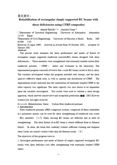
英文原文:Rehabilitation of rectangular simply supported RC beams with shear deficiencies using CFRP compositesAhmed Khalifa a,*, Antonio Nanni ba Department of Structural Engineering,University of Alexandria,Alexandria 21544,Egyptb Department of Civil Engineering,University of Missouri at Rolla,Rolla,MO 65409,USAReceived 28 April 1999;received in revised form 30 October 2001;accepted 10 January 2002AbstractThe present study examines the shear performance and modes of failure of rectangular simply supported reinforced concrete(RC) beams designed with shear deficiencies。
These members were strengthened with externally bonded carbon fiber reinforced polymer (CFRP)sheets and evaluated in the laboratory. The experimental program consisted of twelve full—scale RC beams tested to fail in shear. The variables investigated within this program included steel stirrups, and the shear span-to—effective depth ratio, as well as amount and distribution of CFRP。
土木工程专业外文翻译--钢筋混凝土结构设计
外文原文:Design of Reinforced Concrete StructuresSecond Edition(USA) Williams·Alan2Structure in Design of Architecture And StructuralMaterial,China Water Power Press,Beijing,2002. P37~57钢筋混凝土结构设计第二版(美)艾伦·威廉斯著第二章,在建筑学的设计构成和结构的材料,中国水利水电出版社,北京,2002.P37页~57页.Structure in Design of Architecture And Structural Material We have and the architects must deal with the spatial aspect of activity, physical, and symbolic needs in such a way that overall performance integrity is assured. Hence, he or she well wants to think of evolving a building environment as a total system of interacting and space forming subsystems. Is represents a complex challenge, and to meet it the architect will need a hierarchic design process that provides at least three levels of feedback thinking: schematic, preliminary, and final.Such a hierarchy is necessary if he or she is to avoid being confused , atconceptual stages of design thinking ,by the myriad detail issues that candistract attention from more basic considerations .In fact , we can say thatan architect’s ability to distinguish the more basic form the more detailedissues is essential to his success as a designer .The object of the schematic feed back level is to generate and evaluate overallsite-plan, activity-interaction, and building-configuration options .To do sothe architect must be able to focus on the interaction of the basic attributes of the site context, the spatial organization, and the symbolism as determinants of physical form. This means that ,in schematic terms ,the architect may first conceive and model a building design as an organizational abstraction of essential performance-space in teractions.Then he or she may explore the overall space-form implications of the abstraction. As an actual building configuration option begins to emerge, it will be modified to include consideration for basic site conditions.At the schematic stage, it would also be helpful if the designer could visualize his or her options for achieving overall structural integrity and consider the constructive feasibility and economic of his or her scheme .But this will require that the architect and/or a consultant be able to conceptualize total-system structural options in terms of elemental detail .Such overall thinking can be easily fed back to improve the space-form scheme.At the preliminary level, the architect’s emphasis will shift to the elaboration of his or her more promising schematic design options .Here the architect’s structural needs will shift to approximate design of specific subsystem options. At this stage the total structural scheme is developed to a middle level of specificity by focusing on identification and design of major subsystems to the extent that their key geometric, component, and interactive properties are established .Basic subsystem interaction and design conflicts can thus be identified and resolved in the context of total-system objectives. Consultants can play a significant part in this effort; these preliminary-level decisions may also result in feedback that calls for refinement or even major change in schematic concepts.When the designer and the client are satisfied with the feasibility of a design proposal at the preliminary level, it means that the basic problems of overall design are solved and details are not likely to produce major change .The focus shifts again ,and the design process moves into the final level .At this stagethe emphasis will be on the detailed development of all subsystem specifics . Here the role of specialists from various fields, including structural engineering, is much larger, since all detail of the preliminary design must be worked out. Decisions made at this level may produce feedback into Level II that will result in changes. However, if Levels I and II are handled with insight, the relationship between the overall decisions, made at the schematic and preliminary levels, and the specifics of the final level should be such that gross redesign is not in question, Rather, the entire process should be one of moving in an evolutionary fashion from creation and refinement (or modification) of the more general properties of a total-system design concept, to the fleshing out of requisite elements and details.To summarize: At Level I, the architect must first establish, in conceptual terms, the overall space-form feasibility of basic schematic options. At this stage, collaboration with specialists can be helpful, but only if in the form of overall thinking. At Level II, the architect must be able to identify the major subsystem requirements implied by the scheme and substantial their interactive feasibility by approximating key component properties .That is, the properties of major subsystems need be worked out only in sufficient depth to very the inherent compatibility of their basic form-related and behavioral interaction . This will mean a somewhat more specific form of collaboration with specialists then that in level I .At level III ,the architect and the specific form of collaboration with specialists then that providing for all of the elemental design specifics required to produce biddable construction documents . Of course this success comes from the development of the Structural Material. The principal construction materials of earlier times were wood and masonry brick, stone, or tile, and similar materials. The courses or layers were bound together with mortar or bitumen, a tar like substance, or some other binding agent. The Greeks and Romans sometimes used iron rods or claps to strengthen their building. The columns of the Parthenon in Athens, for example, have holes drilled in themfor iron bars that have now rusted away. The Romans also used a natural cement called puzzling, made from volcanic ash, that became as hard as stone under water. Both steel and cement, the two most important construction materials of modern times, were introduced in the nineteenth century. Steel, basically an alloy of iron and a small amount of carbon had been made up to that time by a laborious process that restricted it to such special uses as sword blades. After the invention of the Bessemer process in 1856, steel was available in large quantities at low prices. The enormous advantage of steel is its tensile force which, as we have seen, tends to pull apart many materials. New alloys have further, which is a tendency for it to weaken as a result of continual changes in stress.Modern cement, called Portland cement, was invented in 1824. It is a mixture of limestone and clay, which is heated and then ground into a power. It is mixed at or near the construction site with sand, aggregate small stones, crushed rock, or gravel, and water to make concrete. Different proportions of the ingredients produce concrete with different strength and weight. Concrete is very versatile; it can be poured, pumped, or even sprayed into all kinds of shapes. And whereas steel has great tensile strength, concrete has great strength under compression. Thus, the two substances complement each other.They also complement each other in another way: they have almost the same rate of contraction and expansion. They therefore can work together in situations where both compression and tension are factors. Steel rods are embedded in concrete to make reinforced concrete in concrete beams or structures where tensions will develop. Concrete and steel also form such a strong bond─ the force that unites them─ that the steel cannot slip within the concrete. Still another advantage is that steel does not rust in concrete. Acid corrodes steel, whereas concrete has an alkaline chemical reaction, the opposite of acid. The adoption of structural steel and reinforced concrete caused major changes in traditional construction practices. It was no longer necessary to use thickwalls of stone or brick for multistory buildings, and it became much simpler to build fire-resistant floors. Both these changes served to reduce the cost of construction. It also became possible to erect buildings with greater heights and longer spans.Since the weight of modern structures is carried by the steel or concrete frame, the walls do not support the building. They have become curtain walls, which keep out the weather and let in light. In the earlier steel or concrete frame building, the curtain walls were generally made of masonry; they had the solid look of bearing walls. Today, however, curtain walls are often made of lightweight materials such as glass, aluminum, or plastic, in various combinations.Another advance in steel construction is the method of fastening together the beams. For many years the standard method was riveting. A rivet is a bolt with a head that looks like a blunt screw without threads. It is heated, placed in holes through the pieces of steel, and a second head is formed at the other end by hammering it to hold it in place. Riveting has now largely been replaced by welding, the joining together of pieces of steel by melting a steel material between them under high heat.Priestess’s concrete is an improved form of reinforcement. Steel rods are bent into the shapes to give them the necessary degree of tensile strengths. They are then used to priestess concrete, usually by one of two different methods. The first is to leave channels in a concrete beam that correspond to the shapes of the steel rods. When the rods are run through the channels, they are then bonded to the concrete by filling the channels with grout, a thin mortar or binding agent. In the other (and more common) method, the priestesses steel rods are placed in the lower part of a form that corresponds to the shape of the finished structure, and the concrete is poured around them. Priestess’s concrete uses less steel and less concrete. Because it is a highly desirable material. Progressed concrete has made it possible to develop buildings with unusualshapes, like some of the modern, sports arenas, with large spaces unbroken by any obstructing supports. The uses for this relatively new structural method are constantly being developed.中文译文:在建筑学的设计构成和结构的材料我们有,并且建筑师一定在一个如此的方法中处理活动,身体检查和代号需要的空间方面全部的表现正直被保证。
土木工程专业英语(苏小卒)课文翻译3~5单元

Unit 3 (从第三段开始)现代水泥发明于1824年,称为波特兰水泥。
它是石灰石和粘土的混合物,加热后磨成粉末。
在或靠近施工现场,将水泥与砂、骨料(小石头、压碎的岩石或砾石)、水混合而制成混凝土。
不同比例的配料会制造出不同强度和重量的混凝土。
混凝土的用途很多,可以浇筑、泵送甚至喷射成各种形状。
混凝土具有很大的抗压强度,而钢材具有很大的抗拉强度。
这样,两种材料可以互补。
They also complement each other in another way: they have almost the same rate of contraction and expansion. They therefore can work together in situations where(在…情况下)both compression and tension are factors(主要因素). Steel rods(钢筋)are embedded in(埋入)concrete to make reinforced concrete in concrete beams or structures where tension will develop (出现). Concrete and steel also form such a strong bond - the force that unites(粘合)them - that the steel cannot slip(滑移)with the concrete. Still(还有)another advantage is that steel does not rust in concrete. Acid(酸)corrodes steel, whereas concrete has an alkaline chemical reaction, the opposite of acid.它们也以另外一种方式互补:它们几乎有相同的收缩率和膨胀率。
土木工程-毕业设计-论文-外文翻译-中英文对照
英文原文:Concrete structure reinforcement designSheyanb oⅠWangchenji aⅡⅠFoundation Engineering Co., Ltd. Heilongjiang DongyuⅡHeilongjiang Province, East Building Foundation Engineering Co., Ltd. CoalAbstract:structure in the long-term natural environment and under the use environment's function, its function is weaken inevitably gradually, our structural engineering's duty not just must finish the building earlier period the project work, but must be able the science appraisal structure damage objective law and the degree, and adopts the effective method guarantee structure the security use, that the structure reinforcement will become an important work. What may foresee will be the 21st century, the human building also by the concrete structure, the steel structure, the bricking-up structure and so on primarily, the present stage I will think us in the structure reinforcement this aspect research should also take this as the main breakthrough direction.Key word:Concrete structure reinforcement bricking-up structure reinforcement steel structure reinforcement1 Concrete structure reinforcementConcrete structure's reinforcement divides into the direct reinforcement and reinforces two kinds indirectly, when the design may act according to the actual condition and the operation requirements choice being suitable method and the necessary technology.1.1the direct reinforcement's general method1)Enlarges the section reinforcement lawAdds the concretes cast-in-place level in the reinforced concrete member in bending compression zone, may increase the section effective height, the expansion cross sectional area, thus enhances the component right section anti-curved, the oblique section anti-cuts ability and the section rigidity, plays the reinforcement reinforcement the role.In the suitable muscle scope, the concretes change curved the component right section supporting capacity increase along with the area of reinforcement and the intensity enhance. In the original component right section ratio of reinforcement not too high situation, increases the main reinforcement area to be possible to propose the plateau component right section anti-curved supporting capacity effectively. Is pulled in the section the area to add the cast-in-place concrete jacket to increase the component section, through new Canada partial and original component joint work, but enhances the component supporting capacity effectively, improvement normal operational performance.Enlarges the section reinforcement law construction craft simply, compatible, and has the mature design and the construction experience; Is suitable in Liang, the board, the column, the wall and the general structure concretes reinforcement; But scene construction's wet operating time is long, to produces has certain influence with the life, and after reinforcing the building clearance has certain reduction.2) Replacement concretes reinforcement lawThis law's merit with enlarges the method of sections to be close, and after reinforcing, does not affect building's clearance, but similar existence construction wet operating time long shortcoming; Is suitable somewhat low or has concretes carrier's and so on serious defect Liang, column in the compression zone concretes intensity reinforcement.3) the caking outsourcing section reinforcement lawOutside the Baotou Steel Factory reinforcement is wraps in the section or the steel plate is reinforced component's outside, outside the Baotou Steel Factory reinforces reinforced concrete Liang to use the wet outsourcing law generally, namely uses the epoxy resinification to be in the milk and so on methods with to reinforce the section the construction commission to cake a whole, after the reinforcement component, because is pulled with the compressed steel cross sectional area large scale enhancement, therefore right section supporting capacity and section rigidity large scale enhancement.This law also said that the wet outside Baotou Steel Factory reinforcement law, the stress is reliable, the construction is simple, the scene work load is small, but is big with the steel quantity, and uses in above not suitably 600C in the non-protection's situation the high temperature place; Is suitable does not allow in the use obviously to increase the original component section size, but requests to sharpen its bearing capacity large scale the concrete structure reinforcement.4) Sticks the steel reinforcement lawOutside the reinforced concrete member in bending sticks the steel reinforcement is (right section is pulled in the component supporting capacity insufficient sector area, right section compression zone or oblique section) the superficial glue steel plate, like this may enhance is reinforced component's supporting capacity, and constructs conveniently.This law construction is fast, the scene not wet work or only has the plastering and so on few wet works, to produces is small with the life influence, and after reinforcing, is not remarkable to the original structure outward appearance and the original clearance affects, but the reinforcement effect is decided to a great extent by the gummy craft and the operational level; Is suitable in the withstanding static function, and is in the normal humidity environment to bend or the tension member reinforcement.5) Glue fibre reinforcement plastic reinforcement lawOutside pastes the textile fiber reinforcement is pastes with the cementing material the fibre reinforcement compound materials in is reinforced the component to pull the region, causes it with to reinforce the section joint work, achieves sharpens the component bearing capacity the goal. Besides has glues the steel plate similar merit, but also has anticorrosive muddy, bears moistly, does not increase the self-weight of structure nearly, durably, the maintenance cost low status merit, but needs special fire protection processing, is suitable in each kind of stress nature concrete structure component and the general construction.This law's good and bad points with enlarge the method of sections to be close; Is suitable reinforcement which is insufficient in the concrete structure component oblique section supporting capacity, or must exert the crosswise binding force to the compressional member the situation.6) Reeling lawThis law's good and bad points with enlarge the method of sections to be close; Is suitable reinforcement which is insufficient in the concrete structure component oblique section supporting capacity, or must exert the crosswise binding force to the compressional member the situation.7) Fang bolt anchor lawThis law is suitable in the concretes intensity rank is the C20~C60 concretes load-bearing member transformation, the reinforcement; It is not suitable for already the above structure which and the light quality structure makes decent seriously. 1.2The indirect reinforcement's general method1)Pre-stressed reinforcement law(1)Thepre-stressed horizontal tension bar reinforces concretes member in bending,because the pre-stressed and increases the exterior load the combined action, in the tension bar has the axial tension, this strength eccentric transmits on the component through the pole end anchor (, when tension bar and Liang board bottom surface close fitting, tension bar can look for tune together with component, this fashion has partial pressures to transmit directly for component bottom surface), has the eccentric compression function in the component, this function has overcome the bending moment which outside the part the load produces, reduced outside the load effect, thus sharpened component's anti-curved ability. At the same time, because the tension bar passes to component's pressure function, the component crack development can alleviate, the control, the oblique section anti-to cut the supporting capacity also along with it enhancement.As a result of the horizontal lifting stem's function, the original component's section stress characteristic by received bends turned the eccentric compression, therefore, after the reinforcement, component's supporting capacity was mainly decided in bends under the condition the original component's supporting capacity 。
- 1、下载文档前请自行甄别文档内容的完整性,平台不提供额外的编辑、内容补充、找答案等附加服务。
- 2、"仅部分预览"的文档,不可在线预览部分如存在完整性等问题,可反馈申请退款(可完整预览的文档不适用该条件!)。
- 3、如文档侵犯您的权益,请联系客服反馈,我们会尽快为您处理(人工客服工作时间:9:00-18:30)。
forced concrete structure reinforced with an overviewRein Since the reform and opening up, with the national economy's rapid and sustained development of a reinforced concrete structure built, reinforced with the development of technology has been great. Therefore, to promote the use of advanced technology reinforced connecting to improve project quality and speed up the pace of construction, improve labor productivity, reduce costs, and is of great significance.Reinforced steel bars connecting technologies can be divided into two broad categories linking welding machinery and steel. There are six types of welding steel welding methods, and some apply to the prefabricated plant, and some apply to the construction site, some of both apply. There are three types of machinery commonly used reinforcement linking method primarily applicable to the construction site. Ways has its own characteristics and different application, and in the continuous development and improvement. In actual production, should be based on specific conditions of work, working environment and technical requirements, the choice of suitable methods to achieve the best overall efficiency.1、steel mechanical link1.1 radial squeeze linkWill be a steel sleeve in two sets to the highly-reinforced Department with superhigh pressure hydraulic equipment (squeeze tongs) along steel sleeve radial squeeze steel casing, in squeezing out tongs squeeze pressure role of a steel sleeve plasticity deformation closely integrated with reinforced through reinforced steel sleeve and Wang Liang's Position will be two solid steel bars linkedCharacteristic: Connect intensity to be high, performance reliable, can bear high stress draw and pigeonhole the load and tired load repeatedly.Easy and simple to handle, construction fast, save energy and material, comprehensive economy profitable, this method has been already a large amount of application in the project.Applicable scope : Suitable for Ⅱ , Ⅲ , Ⅳ grade reinforcing bar (including welding bad reinforcing bar ) with ribbing of Ф 18- 50mm, connection between the same diameter or different diameters reinforcing bar .1.2must squeeze linkExtruders used in the covers, reinforced axis along the cold metal sleeve squeeze dedicated to insert sleeve Lane two hot rolling steel drums into a highly integrated mechanical linking methods.Characteristic: Easy to operate and joining fast and not having flame homework , can construct for 24 hours , save a large number of reinforcing bars and energy. Applicable scope : Suitable for , set up according to first and second class antidetonation requirement -proof armored concrete structure ФⅡ , Ⅲ grade reinforcing bar with ribbing of hot rolling of 20- 32mm join and construct live.1.3 cone thread connectingUsing cone thread to bear pulled, pressed both effort and self-locking nature, undergo good principles will be reinforced by linking into cone-processing thread at the moment the value of integration into the joints connecting steel bars.Characteristic: Simple , all right preparatory cut of the craft , connecting fast, concentricity is good, have pattern person who restrain from advantage reinforcing bar carbon content.Applicable scope : Suitable for the concrete structure of the industry , civil building and general structures, reinforcing bar diameter is for Фfor the the 16- 40mm one Ⅱ , Ⅲ grade verticality, it is the oblique to or reinforcing bars horizontal join construct live.conclusionsThese are now commonly used to connect steel synthesis methods, which links technology in the United States, Britain, Japan and other countries are widely used. There are different ways to connect their different characteristics and scope of the actual construction of production depending on the specific project choose a suitable method of connecting to achieve both energy conservation and saving time limit for a project ends.钢筋混凝土结构中钢筋连接综述改革开放以来,随着国民经济的快速、持久发展,各种钢筋混凝土建筑结构大量建造,钢筋连接技术得到很大的发展。
因此,推广应用先进的钢筋连接技术,对于提高工程质量、加快施工速度、提高劳动生产率、降低成本,具有十分重要的意义。
钢筋连接技术可分为钢筋焊接和钢筋机械连接两大类。
钢筋焊接有6种焊接方法,有的适用于预制厂,有的适用于现场施工,有的两者都适用。
钢筋机械连接常用有3种方法,主要适用于现场施工。
各种方法有其自身特点和不同的适用范围,并在不断发展和改进。
在实际生产中,应根据具体的工作条件、工作环境和技术要求,选用合适的方法以期达到最佳的综合效益。
1、钢筋机械连接1.1径向挤压连接将一个钢套筒套在两根带肋钢筋的端部,用超高压液压设备(挤压钳)沿钢套筒径向挤压钢套管,在挤压钳挤压力作用下,钢套筒产生塑性变形与钢筋紧密结合,通过钢套筒与钢筋横肋的咬合,将两根钢筋牢固连接在一起。
特点:接头强度高,性能可靠,能够承受高应力反复拉压载荷及疲劳载荷。
操作简便、施工速度快、节约能源和材料、综合经济效益好,该方法已在工程中大量应用。
适用范围:适用于Ф18~50mm的Ⅱ、Ⅲ、Ⅳ级带肋钢筋(包括焊接性差的钢筋),相同直径或不同直径钢筋之间的连接。