艾默生说明书标准-3版
ES艾默生说明书

UNIDRIVE ES 电梯专用变频器用户手册E1-20030818-C-1.0 (BOM:31010957)E m e r s o n I n d u s t i a l A u t o m a t i o n一般信息因用户疏忽或不当安装或不当调节设备操作参数,或将变频器与不适配的电机搭配使用所导致的任何后果,厂家概不负责。
本手册中的内容,在付印时我们已确认是正确的。
但我公司致力于持续改进产品,因此厂家保留修改该产品规格、性能及本手册其它内容的权力,并不另通知用户。
厂家保留所有权力。
本手册的任何内容,未经厂家书面同意,不得以任何形式复制(包括:影印、记录于存储器或可调用系统)和传播。
变频器软件版本本产品所附带的软件为最新版本。
如果将本产品和其它变频器一起用于新的或现存的系统,由于各变频器软件版本可能不同,将导致本产品功能上的差异。
从本公司用服部门退回的变频器也会有以上问题。
欲知软件版本,可查看Pr11.29(或Pr0.50)及Pr11.34。
软件版本为zz.yy.xx,Pr11.29显示zz.yy,Pr11.34显示xx。
例如:软件版本01.01.00,Pr11.29显示01.01,Pr11.34显示0。
如有疑问,请咨询我公司。
环境声明我公司致力于降低工厂及产品(在整个生命周期内)对环境的影响。
为此,我公司应用了“环境管理系统(EMS)”(Environmental Management System),该系统通过ISO14001认证。
关于EMS的详细信息、我公司的环保政策或其它,请与我们联系,或访问.我公司生产的变频器在长期使用中,可以节能、减少原材料的消耗及浪费。
该产品的上述优点远远抵消了它生产过程中及报废时对环境的影响。
当产品到达服务年限后,可将其方便的拆卸成几大部件,便于循环利用。
该产品大部分部件都是卡入式安装,拆卸时不需使用工具,其它部分用螺钉紧固,方便拆卸。
实际上,各部分零件皆可循环利用。
艾默生TD3100变频器说明书

TD3100系列电梯专用变频器用户手册版本:V1.2归档日期:2005-11-10BOM:31010404艾默生网络能源有限公司为客户提供全方位的技术支持,客户可与就近的艾默生网络能源有限公司办事处或客户服务中心联系,也可直接与公司总部联系。
版权所有,保留所有权利。
内容如有改动,恕不另行通知。
艾默生网络能源有限公司深圳市南山区科技工业园科发路一号邮政编码:518057公司网址:客户服务热线:800-820-6510手机及未开通800地区请拨打:021-********客户服务投诉热线:0755-********E-mail:info@出版说明内容提要本手册对艾默生网络能源有限公司TD3100系列电梯专用变频器的安装、使用、维护进行了全面系统的阐述。
本手册可作为采用TD3100系列电梯专用变频器进行系统设计的参考资料。
读者对象用户变频器设计工程师工程维护人员用户技术支援人员序言感谢您使用艾默生网络能源有限公司TD3100系列电梯专用变频器。
TD3100 系列变频器是艾默生网络能源有限公司自主开发生产的多功能、高品质、低噪音电梯专用矢量控制型变频器,完全可满足您对各种电梯控制系统的需求。
它具有结构紧凑,安装方便的特点,其先进的矢量控制算法、距离控制算法、电机参数自动调谐、转矩偏置、井道位置自学习、抱闸接触器控制、预开门监测等多种智能控制功能可满足您对系统高精度控制要求;检修运行、蓄电池运行、自学习运行、多段速运行、强迫减速运行等多种特殊运行控制方式及其普通可编程开关量输入、逻辑可编程开关量输入有助于实现电梯控制的全面解决方案;抱闸接触器检测、电梯超速检测、输入输出逻辑检测、平层信号与电梯位置检测等功能保证了系统运行的安全性;国际标准化设计和测试,保证了产品的可靠性。
使用TD3100系列电梯专用变频器之前,请您仔细阅读本手册,以保证正确使用并充分发挥其优越性能。
另外,本手册为随机发送的附件,请您使用后务必妥善保管,以备变频器检修和维护时使用。
艾默生ASCO系列电磁阀使用说明书
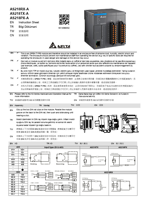
AS218RX-A AS218TX-AAS218PX-A5014086002EN Instruction Sheet TR Bilgi DökümaniTW 安裝說明 CN安装说明ENThis is an OPEN TYPE module and therefore should be installed in an enclosure free of airborne dust, humidity, electric shock andvibration. The enclosure should prevent non-maintenance staff from operating the device (e.g. key or specific tools are required for operating the enclosure) in case danger and damage on the device may occur.FRCeci est un module ouvert et il doit donc être installé dans un coffret à l’abri des poussières, des vibrations et ne pas être exposé auxchocs électriques. Le boitier ou l’armoire doit éviter toute action d’un personnel autre que celui affecté à la maintenance de l’appareil (par exemple, clefs, outils spécifiques pour l’ouverture du coffret), ceci afin d’éviter tout accident corporel ou endommagement du produit).TRBu ürün AÇIK TİP bir modül olup toz, rutubet, elektrik şoku ve titreşimden uzak kapalı yerlerde muhafaza edilmelidir. Yanlış kullanımsonucu ürünün zarar görmesini önlemek için yetkili olmayan kişiler tarafından ürüne müdahale edilmesini önleyecek koruyucu önlemler alınmalıdır. (Ürünün bulunduğu panoya kilit konulması gibi).TW本機為開放型(OPEN TYPE )機種,因此使用者使用本機時,必須將之安裝於具防塵、防潮及免於電擊∕衝擊意外之外殼配線箱內。
艾默生涡旋变频压缩机和电控解决方案说明书

艾默生全系列涡旋变频压缩机和电控解决方案全面的安全保护和可靠性谷轮涡旋TM 压缩机传承了CoreSense TM 保护技术,将产品可靠性提升到新的高度。
通过将主动保护算法集成于电机控制变频器中,确保压缩机和变频器在各种异常工况运行的安全性。
主要有以下保护特征:• 电机和涡旋温度保护• 电机堵转检测• 相序保护和更正• 最大运行电流检测• 排气温度保护• 频繁启停循环保护该系列变频压缩机产品建立在高度的可靠性和经过验证的高性能基础之上,融合了艾默生25年的涡旋压缩机技术及全世界超过1亿台的运行经验。
为了帮助客户应对变频化的市场趋势,艾默生开发了4~25HP 变频压缩机和变频器的整体解决方案,全系列产品搭载多项创新技术,以业界顶级能效水平助力系统进入能效升级新时代。
结合谷轮引以为豪的喷气增焓技术,超低温环境下也能保证系统强效制热安全可靠。
同时推出的艾默生EVD 系列变频器专门针对永磁电机设计,完美匹配变频压缩机,一站式解决方案帮助客户快速响应市场需求。
变频压缩机型谱图浮动密封圈变容积比涡旋喷气增焓技术(可选)导油管高效集中卷六极永磁电机3.4mm厚壳设计柔性液体刹车容积式油泵谷轮涡旋™变频压缩机优势:• 优异的性能和噪音表现• 卓越的可靠性• 搭载高效艾默生永磁电机有效提升节能效果• 中国研发中心为亚太市场应用量身打造,苏州生产• 广泛适用于变频多联机、柜式空调、地暖等应用• 900-7200rpm 宽广频率范围,让系统设计更加游刃有余• 可变容积比技术(VVR)显著改善涡旋低转速下的能效运行范围喷气增焓(EVI)技术特点:• 专利技术的喷气增焓结构设计• EVI 回路气体进入压缩机后,通过特殊设计的通道注入涡旋, 注入涡旋的气体经过压缩,和吸气口吸入的气体一起排出,进入制冷循环• 喷气增焓带来制热能力的上升和排气温度的降低• 喷气增焓可取代系统辅助电加热艾默生谷轮涡旋™变频压缩机给家用制冷和制热系统带来了变革。
艾默生 Commander SK 2~6型 交流变速驱动器 说明书

1 ڔཝቧᇦ ..................................................7
1.1 警告、小心及注意 .................................................7 1.2 电气安全 - 一般警告 ............................................7 1.3 系统设计及人身安全 ..............................................7 1.4 环境要求 ................................................................7 1.5 操作 .......................................................................7 1.6 防火保护 ................................................................7 1.7 遵守规定 ................................................................7 1.8 电机 .......................................................................7 1.9 调整参数 ................................................................7 1.10 电气安装 ................................................................7 1.11 机械安装 ................................................................8
艾默生管道工具(上海) 套丝机 中文说明书

套丝机中文操作手册艾默生管道工具(上海)有限公司目录机器型号和序列号记录表格 (3)安全须知 (4)工作场所安全注意事项 (4)用电安全 (4)个人安全注意事项 (5)工具的使用与保养 (5)服务 (5)其它安全注意事项脚踏开关的使用安全 (5)套丝机使用安全 (6)产品概述、技术参数与标准配置产品概述 (6)技术参数 (6)标准配置 (7)附件 (7)牙模头和板牙 (7)机器安装安装支架 (9)安装到通用支架 (9)安装到1406支架 (10)安装油盘盖 (10)安装到工作台上 (11)用1406搬运套丝机 (11)用提升设备、牵引设备搬运机器 (11)机器检查 (11)机器和工作区域设置 (13)套丝操作步骤安装管子 (14)用364割刀切割管子 (14)344铰刀铰孔 (15)动力套丝 (16)拆下管子 (12)安装板牙到快开牙模头 (17)安装板牙到自开牙模头 (17)安装板牙半自动牙模头 (18)检查螺纹 (19)819短管工具安装短管工具 (20)短管工具使用 (20)使用齿轮套丝器操作步骤套丝尺寸调整步骤 (21)安装141齿轮套丝器 (22)使用840万向驱动轴来安装141和161齿轮套丝器 (22)套丝 (23)821割刀和822适配器 (23)左旋套丝 (23)附件 (24)保养指导油路系统维护 (25)润滑 (25)卡爪更换 (25)套丝塑料管更换卡爪 (25)机器存放要求 (25)维修与服务 (26)线路图 (26)终身质保条款........................................................................................................................封底1822-I 型套丝机1822-I 型套丝机在下面空格内记下产品序列号,并妥善保存写有产品序列号的铭牌。
序列号安全须知警告!请仔细阅读所有的安全注意事项和安全指导。
艾默生 Micro Motion G系列流量和密度仪表 说明书
产品样本00813-0106-4630, Rev AA2023 年 10 月Micro Motion(高准)G 系列流量和密度仪表™出色的可靠性和安全性■无磨损或需要更换的移动部件,将维护工作降到最少,保证了长期的可靠性■激光蚀刻标签,即使在具有挑战性的环境中也非常耐用■可清洁、自排空设计连接■全系列的高准变送器选项和通信协议■通过创新的 Wi-Fi、Bluetooth®、2 线环路供电和以太网供电解决方案降低布线的复杂性■包括 Smart Meter Verification 在内的高级诊断易于使用■超紧凑式轻质传感器设计确保安装灵活性■具有值得信赖的高准电子元件,易于安装、集成和远程监测■简化的传感器选项和预选解决方案,便于订购G 系列科里奥利质量流量计和密度仪表2023 年 10 月测量原理作为科里奥利效应的实际应用,科里奥利质量流量计的工作原理是使得有介质流经的流量管发生振动。
尽管振动并非完整的圆形,仍形成了旋转坐标系统,从而引发科里奥利效应。
传感器将检测并分析流量管频率,相位差和振幅的变化。
具体的检测方法会因流量计设计不同而不同,这些被观测到的变化代表了流体的质量流量和密度。
密度测量测量管以其固有频率振动。
管道内流体质量的变化将导致管道固有频率发生相应的变化。
通过管道的频率变化来计算密度。
温度测量温度作为测量变量,可用作输出量。
此外,温度还可在传感器内部使用,以补偿温度变化对杨氏弹性模量的影响。
质量和体积流量测量测量管在力的作用下发生摆动,从而产生正弦波。
流量为零时,两根管道同相地发生振动。
有流量时,科里奥利力促使管道发生扭曲,从而引发相偏移。
测量正弦波之间的时差,此时差与质量流量成正比。
体积流量通过质量流量和密度测量结果来计算得到。
请观看此视频,详细了解科里奥利流量计如何测量质量流量和密度(单击链接,选择View Videos(查看视频)):https:// /en-us/automation/measurement-instrumentation/flow-measurement/coriolis-flow-meters。
艾默生 VANESSA 三偏心阀门解决方案 使用说明书
由于存在火花点燃风险,对液态氧和气态氧的处理具有一定的挑战性。
行业需要的解决方案不仅要具备高性能、高可靠性和耐用性,同时还要达到严格的清洁度要求。
VANESSA 三偏心阀门解决方案适用于在富氧工况中安全可靠地进行隔断和工艺调节在空分装置 (ASU) 的内部及周围,液态氧 (LOX) 是低温蒸馏过程的直接产物,该过程在转化为气态氧 (GOX) 之前进行。
以上过程在热交换器中发生,随后气态氧被运输并用于高炉、化学反应器和许多其它工业应用中。
通常情况下,这些应用面临着影响工厂生产力、安全性、可靠性的问题:使用一个不合格的阀门可能会导致一场重大事故的发生。
可靠的氧气工况阀门必须选择合适的材料,还要满足严格的清洁度要求,才能在液态氧 (LOX) 的低温环境和气态氧 (GOX) 的高压环境中实现出色的隔断和调节性能。
在传统阀门设计中,升降式阀杆和阀体腔可能会有外部颗粒进入,并存在氧相变的风险,可能引起燃烧。
传统的球阀和高性能蝶阀设计尽管已经在液态氧中得到了应用,但在密封过程中仍会存在机械摩擦,这是另一个可能的引燃原因。
球阀也在气态氧 (GOX) 中作为传统阀门广泛应用,但会产生较高的总体安装费用(由于占用空间大、重量重和所需的大扭矩驱动)及高昂的维护成本。
液体储罐空气压缩装置吸附装置热交换器蒸馏塔图 1空分装置产品信息三偏心设计Vanessa 30,000 系列阀门与截止阀具有相同的锥对锥原理,但其密封通过角行程旋转完成。
三偏心阀的密封系统由外形相同(具有倾斜的锥形截面)的固定阀座和旋转密封面组成。
当这两个锥面重叠时,因达到关闭位置而实现密封。
这种"角行程截止阀"的概念是通过使用三个可完全消除摩擦的"偏心"来实现的。
在所有基础、低温和高温配置中将三偏心设计和柔性金属密封环巧妙组合,产品通过优化的阀座角度和旋转特性,从而确保了卓越的密封性。
密封环Vanessa 30,000 系列密封环的弹性和径向压缩使接触压力均匀地分布在阀座表面 - 确保零泄漏*性能。
ES艾默生说明书
UNIDRIVE ES 电梯专用变频器用户手册E1-20030818-C-1.0 (BOM:31010957)E m e r s o n I n d u s t i a l A u t o m a t i o n一般信息因用户疏忽或不当安装或不当调节设备操作参数,或将变频器与不适配的电机搭配使用所导致的任何后果,厂家概不负责。
本手册中的内容,在付印时我们已确认是正确的。
但我公司致力于持续改进产品,因此厂家保留修改该产品规格、性能及本手册其它内容的权力,并不另通知用户。
厂家保留所有权力。
本手册的任何内容,未经厂家书面同意,不得以任何形式复制(包括:影印、记录于存储器或可调用系统)和传播。
变频器软件版本本产品所附带的软件为最新版本。
如果将本产品和其它变频器一起用于新的或现存的系统,由于各变频器软件版本可能不同,将导致本产品功能上的差异。
从本公司用服部门退回的变频器也会有以上问题。
欲知软件版本,可查看Pr11.29(或Pr0.50)及Pr11.34。
软件版本为zz.yy.xx,Pr11.29显示zz.yy,Pr11.34显示xx。
例如:软件版本01.01.00,Pr11.29显示01.01,Pr11.34显示0。
如有疑问,请咨询我公司。
环境声明我公司致力于降低工厂及产品(在整个生命周期内)对环境的影响。
为此,我公司应用了“环境管理系统(EMS)”(Environmental Management System),该系统通过ISO14001认证。
关于EMS的详细信息、我公司的环保政策或其它,请与我们联系,或访问.我公司生产的变频器在长期使用中,可以节能、减少原材料的消耗及浪费。
该产品的上述优点远远抵消了它生产过程中及报废时对环境的影响。
当产品到达服务年限后,可将其方便的拆卸成几大部件,便于循环利用。
该产品大部分部件都是卡入式安装,拆卸时不需使用工具,其它部分用螺钉紧固,方便拆卸。
实际上,各部分零件皆可循环利用。
艾默生空气压缩机手册说明书
PISTON COMPRESSOR MANUAL REV022621Contents Safety Information 2-3 Breathable Air 3Pressurized Components 3Personal Protective Equipment 3 Nomenclature 4 Features and Extras 5-7 Pump Riser 5Belt Tensioner 5Continuous Run 6Automatic Tank Drain 7 Installation 8-16 Area 8Lifting and Movement 9General Lifting 9Anchoring 10Electrical 11-14 Piping 15-16 Pre-use Inspection 17 Operation 18Pump Times 18 Maintenance 19-20 Maintenance Schedule 19-20 Oil Change/Selection 20Oil Disposal 20 FAQ and Troubleshooting 21 Warranty Information 22-24SAFTEY INFORMATIONThis manual contains very important information to know and understand. This is to provide for SAFTEY and to PREVENT EQUIPMENT PROBLEMS. To help understand this information, observe the following:DANGER:Danger indicates and imminently hazardous situation which, if not avoided, will result in death or serious injury.WARNING: Warning indicates a potentially hazardous situation which if not avoided, could result in death or serious injury.CAUTION:Caution indicates a potentially hazardous situation which, if not avoided, may result in minor or moderate injury.NOTICE:Notice indicates important information, that if not followed, may cause damage to equipment.CALIFORNIA PROPOSITION 65WARNING:This product or its power cord may contain chemicals known to the state of California to cause cancer and birth defects or other reproductive harm. Wash hands after handling.1.Allow only trained, authorized persons who have read and understood these operating instructions to use thisequipment. Failure to follow the instructions, procedures and safety precautions in this manual can result inaccidents and injuries.2.NEVER start or operate the compressor under unsafe conditions. Tag the compressor, disconnect,and lock out all power to it to prevent accidental start-up until the condition is corrected.3.Install, use, and operate the compressor only in full compliance with all pertinent OSHAregulations and all applicable Federal, State & Local codes, standards, and regulations.4.NEVER modify the compressor and/or controls in any way.5.Keep a first aid kit in a convenient place. Seek medical assistance promptly in case of injury. Avoidinfection by caring for any small cuts and burns promptly.BREATHABLE AIR1.NEVER use air from this compressor for breathable air except in full compliance with OSHA Standards 29CFR 1910 and any other Federal, State or Local codes or regulations.2.DO NOT use airline anti-icer systems in air lines supplying respirators or other equipment used to producebreathable air. DO NOT discharge air from these systems in unventilated or other confined areas.Pressurized ComponentsThis equipment is supplied with an ASME designed and rated pressure vesselprotected by an ASME rated relief valve. Pull the ring before each use toensure the valve is functional. DO NOTattempt to open the valve while themachine is under pressure. See figure on the right.Personal Protective EquipmentBe sure all Be sure all operators and others around the compressor and its controls comply with all applicable OSHA, Federal, State and Local regulations, codes, and standards relating to personal protective equipment. This includes respiratory protective equipment, protection for the extremities, protective clothing, protective shields and barriers, electrical protective equipment, and personal hearing protective equipment.NomenclatureFeatures and ExtrasCompressors come in many shapes and sizes. Our units have several features that may or may not be present on your unit. These features may be purchased after the fact in kit form. This guide will explain the use and benefit of these features.Pump RiserBelt TensionerContinuous RunContinuous run allows the pump to turn continuously, hence the name. In this mode the unit pumps up to 140 PSI and then the valves are held close. This allows the pump to enter a free spin state where the unit is pulling in cold air and the simply cycling it back to atmosphere. This has several benefits:1.The pump is cooled during the free spin state since it has no pump load on it.2.Increased recovery time since the function cycles between 100 and 140 PSI; which is the optimal CFMwindow for the unit.3.Wear on your motor is decreased (especially single-phase units) as the unit is already in motion and will notneed the large amp draw to overcome zero movement and fight tank compression.4.Continuous run is best used in applications where CFM cannot be lost. Some examples of this are: mediablasting, painting, and prolonged grinding or resurfacing.Auto DrainAuto drains are preset timer valves that allow tank moisture to be vented as long as they are powered. The enemy of every compressor/air system is moisture. The auto drain removes some of the hassle of this by allowing the user to set a timer and walk away from the unit with the piece of mind that their system is protected.1. The drain works off a conventional 120V outlet.2. Timer has built in intervals that can be customized to the user need.3. Has a manual shut off for service and maintenance.4. The drain filter MUST be cleaned weekly to prevent drain blockage.5.Drain time knob, marked as ON:SEC , corresponds to how long the drain will run for when it comes on. This is listed in seconds.6. Drain interval knob, marked as OFF: MIN , corresponds to how long between cycles. Or how long the drainwill be OFF before it comes on again.7. The drain attaches to a ½” NPT female connection.8. The vent can blow to atmosphere; however, the drain is supplied with a drain silencer system which can beused to muffle the sound of the unit draining. This screws into the atmospheric vent location, however, it is not necessary for operation.9.A drain system can also be equipped by the user to allow moisture to drain to a separate location.10. The drain is also equipped with a test button to check function.InstallationArea1.Install compressor in a clean, dry, and well-lit area. Be sure installation area can maintain a temperaturerange between 35˚ - 110˚F.2.Allow sufficient space around the compressor for maintenance access and adequate airflow. Mount unit withthe belt guard (pulley and flywheel) side to the wall and leave a minimum of 15 inches of clearance.3.If acid is used in operating environment or air is dust laden, pipe intake to outside fresh air. Increase pipe sizeby 1/8”’ for every 20ft of run. Be sure to install a protective hood at the outside air intake location to prevent debris and foreign objects from blocking the intake pipe.4.In operating environments where excessive water, oil, dirt, acid, or alkaline fumes are present, a TEFC (totallyenclosed, fan cooled) motor is highly recommended. Check nameplates for motor type.5.Insulate cold water or tother low temperature pipes that pass overhead to avoid condensation dripping onthe compressor.6.In environments where fine dust is common such as granite, marble, or concrete plants the unit must beinstalled in a separate room with its own dedicated ventilation system.7.The unit can be stored outside under the following guidelines: It must be in a covered area out of extremeweather with no ability for moisture to get to the unit, it is also highly recommended that the unit is out of direct sunlight as it can fade and/or damage the coating on the unit. Direct sunlight may also interfere with safety decals on the unit.8.If the unit is in an enclosed space it requires proper ventilation as the ambient air temp where thecompressor is located CANNOT exceed 115 degrees F.e shims to level the compressor if installation area is not flat. This will help prevent excessive vibration andpremature pump wear.Lifting and Movement/Forklift1. Make sure lift operator stays aware while moving the compressor.2. Be sure to uncrate the compressor prior to movement. This will allow a visual reference for the balance ofthe unit.3. Be sure the load is secure and well balanced before moving the compressor.4. Make sure the forks are fully engaged and level prior to lifting or moving the unit.5. Keep the unit/load as low as possible while moving and refrain from quick changes in direction.6. For all other forklift safety standards/regulations please reference OSHA 1910.178- Powered industrialtrucks.General Lifting Information1. Carefully inspect all lifting equipment and ensure it is in good condition. Rated capacity of lifting equipmentmust exceed compressor weight. NEVER lift with under sized or damaged equipment.2. If using lifting equipment, ensure all lifting points are in good condition and tighten any loose nuts or boltsbefore lifting.3. A sling MUST be used when moving the compressor with a helicopter or other airborne equipment. Be sureto follow OSHA standards 1910 subpart N.4. Use guide ropes or equivalent to prevent twisting or swinging of the compressor while it is in the air andNEVER attempt to lift the unit in high winds. Keep compressor as low to the ground as possible.5. Keep all persons away from the compressor when it is lifted. DO NOT allow persons under the compressorwhile it is being lifted.6. DO NOT use bolts or other hooks on individual components to move the compressor.7. When moving and or placing the compressor ensure it is on/across a surface that can hold the combinedweight of the compressor and the loading equipment.AnchoringTo ensure proper and safe operation of the compressor the unit is required to be anchored to a flat, smooth,concrete floor. Compressors are also required to be on ¼ inch (6.35mm) MAXIMUM thick rubber anti-vibration pads.Recommended anchor Bolt specifications: wedge anchors; 3/8 in width by 3.5 in length.How to Anchor the Compressor1. Make sure the compressor is in the desired location and the anti-vibration pads are under the feet of thecompressor.2. Using the holes in the feet as guides, drill the holes for the anchor bolts through the vibration pads and intothe concrete.3. Thoroughly clean each hole.4. Put the Washer and Nut into place, make sure the top of the Nut is flush with the top of the anchor bolt, theninsert the anchor bolt into the hole.5. Hammer or mallet the anchor bolt down into the hole.6. Tighten each nut clockwise , DO NOTover tighten. DO NOTuse an impact to tighten the anchors.Electrical Safety1. Follow all NEC and local codes for electrical wiring. Allow only authorized service personnel or certifiedelectricians to install electrical components.2. Put unit on a dedicated circuit and make sure no other electrical equipment is wired into it. Failure to wireunit on an independent circuit can cause circuit overload and/or imbalance in motor phasing. Install proper No Fuse Breaker (NFB) according to the chart listed below. You may also reference NEC and local codes for additional support.3. Ensure incoming service has adequate ampere rating.4. Do not used mixed wire sizes when wiring the unit.5. The unit must be properly grounded. DO NOT connect ground to air or cooling lines.Wiring the Compressor1. Voltage should not vary more than 12% to ensure proper operation of the compressor.2. Wire size and breaker requirements for single phase units:**3. Wire size and breaker requirements for 3 phase units:**Wire size distances are from unit to the panel where the breaker is housed.**CAUTION: Under sizing wires and/or breakers can cause damage to the unit, possible injury to personnel, and void your warranty.4. Single phase unit, NO magnetic starter:5.Single phase unit WITH magnetic starter:6.Three phase unit wire diagram (Three phase will ALWAYS have magnetic starter):7.During initial start up of 3 phase unit, pay attention to flywheel rotation. When facing the front of thecompressor (Pressure switch/pressure gauge side) rotation should be clockwise. If rotation iscounterclockwise, switch incoming power leads at 3L2 and 5L3 (ensure power is off at the breaker before attempting any changes).Piping (Safety steps)1.Install appropriate flow-limiting valves as necessary according to pipe size(s) used and run lengths. This willreduce pressure in case of hose failure, per OSHA Standard 29 CFR 1926.302(b)(7).2.Flow-limiting valve are listed by pipe size and rated CFM. Select appropriate valves according tomanufacturer’s recommendations.e a flexible connector between compressor tank and dryer/piping system to minimize noise, vibration,pump wear, and to prevent damage to the unit or piping system.4.Install ASME code safety valves and ensure piping system is equipped with adequate condensate drains.5.Minimum pipe size for compressed air lines: (Pipe sizes are shown in inches)PISTON COMPRESSOR MANUAL REV0226216.Air systems should be checked daily for leaks. This helps to prevent unnecessary load on the compressor andhelps increase energy savings.7.Examples of air systems:Closed loop system. Install tee fitting in piping from air to minimize pressuredrop and to allow air flow in two directions.Air DropAir Drop: Install tee fitting withbranch to top to minimizecondensation.From CompressorElevation View8.Make sure any tube, pipe, fitting, or hose connected to the unit can withstand operating temperatures andretain pressure.9.Never use reducers in discharge piping. Keep all piping and fittings the same size in the piping system.WARNING: Never use plastic (PVC) pipe for compressed air. Serious injury ordeath could result. Piping MUST have a pressure rating of 200 PSI or greater.Pre-Use Inspection1. The unit is shipped with pump break-in oil and should be ready to operate. Be sure to check for proper oil levelbefore running the compressor. Break in oil should be change after 100 Hours of operation (active pumping time). See maintenance section for more information on oil changes and frequency.2. Check for proper belt tension. There should be ½ inch of belt slack/deflection. Refer to maintenance section ifadjustment is necessary.3. Inspect belts for frays or unit for an excess buildup of black rubber dust indicating belt wear.4. Check proper operation of all pop off safety valves on unit. Pull rings on valves to ensure they move and are freeof any obstructions. DO NOT pull the safety valve on the tank if there is air in the tank!5. Inspect all air lines/piping for proper for secure fit and corrosion or line degradation. DO NOT operate thecompressor with damaged lines. DO NOT use damaged or cracked air lines as a rupture could result in damage/injury to personnel or property.6. WITH UNIT LOCKED OUT (power off at source i,e. the electrical panel/disconnect) ensure all electrical wiring,including all terminals, are in good condition and are free of buildup, fraying, cracks or discoloration replace as needed. Check tightness of bolts securing wiring in place.7. Ensure unit is secured in place and has not shifted. Verify anchor bolts are in place and are in good condition. 8. Remove any loose items from around/on compressor to avoid damage to the unit. Examples would be looseclothing items, rags, papers, bottles, or any item that may have been placed on the unit. 9. Check unit for any oil leaks. If leaks are found contact manufacturer for further instructions. 10. Unit should NEVER be operated without the belt guard in place.11. Inspect Flywheel for cracks or missing fins. NEVER operate a unit with a damaged flywheel; serious injury ordeath could result. If you suspect your flywheel may have been damaged, contact technical assistance and DO NOT allow the machine to be operated.Ensure all personnel that work around or operate the compressor have read this manual and are well versed in the operation of this machinery. NEVER allow untrained personnel to operate this unit.1. Once the inspection is completed, open your discharge port (outlet ball valve). This should already be connectedto your shop airline system.2. Ensure all personnel are clear of the compressor and aware that it is being started.3. Turn the selector on your pressure switch to AUTO. This will start your compressor and allow it to fill. The tankwill fill to 175 PSI, and unless otherwise noted, will shut off. The unit will begin pumping again once the tank is drained down to approximately 135 PSI. ***This may vary based on features, if your unit is equipped withCONTINOUS RUN , the unit may perform differently then specified in this step. (Check the FEATURES section for more information)4. Oil pressure on start up will vary due to ambient temperatures but should not exceed 100 PSI. Once the unit isallowed to run a few cycles and come to optimal operating temperature, oil pressure should stabilize at 20-35 PSI. If the oil pressure remains high or drops too low, it can be adjusted as follows:Pump Up Time (General)Compressor maintenance must be performed as described in the maintenance schedule, failure to do may lead to compressor/component breakdown and void compressor warranty.Maintenance ScheduleThe table below is a generalized maintenance schedule based on the normal usage of a compressor. Your specific needs may vary based on operating environment and duty.Frequency of these changes are a generalization and may be subject to change based on compressor environment, hours, and application.Oil ChoiceIt is strongly advised to use only Airbase Industries piston compressor oil. Check with your warranty/extended warranty guidelines to verify oil selection and use. Oil used in the compressor must fall under the following criteria: synthetic, SAE grade 30, non-detergent, piston compressor oil.Oil DisposalCompressor oil is not trash and MUST NOT be disposed of in regular trash or discarded into the environment. You MUST dispose of waste oil from your unit per all applicable federal, state, and/or local codes. Failure to do so may damaged the environment and subject yourself and/or your business to fines and legal issues.TroubleshootingSome unit issues can be fixed simply by verifying the following guide. It is advised to go through the guide prior to calling technical support to help expedite the assistance process.Warranty Statement•Standard Warranty: That each compressor unit is free from defects in material, workmanship, and parts for1 year from the date of delivery. This Standard Warranty includes 1 year of warranty labor from anauthorized technician. Manufacturer is not responsible for downtime during warranty service. If downtime is necessary, it is at the owner’s discretion, obligation, and expense, to h ave a redundant compressor.• Parts shipped for warranty repairs shall only include ground freight charges for the first 90 days of the warranty period, thereafter owner is responsible for all freight charges of parts shipped for warranty. Any and all expre ss shipping charges of warranty parts would be at the owner’s expense. Standard technicalassistance is provided at no charge during and after the standard warranty period.*Standard warranty has no obligation to maintain warranty status, warranty will expire one year from date of delivery. Please see available options below to extend your warranty.•Extended Warranty: Manufacturer will extend your standard 1-year warranty to full 5 years when you opt to register for the extended warranty plan that includes using our SMART OIL™ and following all routinemaintenance set forth. Parts shipped for warranty repairs shall only include ground freight charges for the first90 days of the warranty period, thereafter owner is responsible for all freight charges of parts shipped forwarranty. Any and all express shipping charges of warranty parts would be at the owner’s expense. Standard technical assistance is provided at no charge during and after the standard warranty period.Required maintenance schedule to maintain warranty status.➢All units are shipped with break-in oil and must be changed no less than 70 hours to i nsure gasket seating.➢After the 100 hours of break-in, you must change the oil.➢Thereafter Oil Should be changed every 6 months or 1000 hours whichever occurs first.➢Always maintain proper oil level in unit. If the unit runs out of oil due to neglect the warranty w ill be void.➢Use only manufacturer approved oils in your compressor, or your warranty is void.➢All stock orders by vendor/purchaser are required to purchase two service kits at time of purchase per unit.➢All stocking orders will have a 6-month grace period for warranty registration. After that time the unit must be registered, or warranty may be void.**Extended Limited Lifetime Pump Warranty With participation in our SMART OIL™ extended auto shipprogram will extend your warranty plan to **Limited Lifetime Warranty on the pressure lubricated pump.All other non-wear and tear components to 10 years. SMART OIL™ not only extends the life of yourcompressor pump, it also can reduce operating noise levels and can create further energy savings.Warranty repair parts under the Limited Lifetime warranty will not include any shipping charges beyondthe Standard Warranty, therefore owner is responsible for all freight charges for warranty parts. This planincludes our advanced technical air support. Smart Tech Support provides you with the highest level oftechnical support. Smart Tech support is an interactive support team available to you at your fingertips byjust downloading a free app. The app provides free remote meetings, interactive touch display, real livepersonal to assist.Limited Lifetime Warranty is not prorated and has no hour limits.**Limited Lifetime Warranty, non-prorated, no hour limits. In the case the product has been discontinuedat any point the Limited lifetime Pump warranty will last five years past the discontinued date. Warrantorhas discretion to substitute parts with current model for the five-year duration.*In order to maintain Limited Lifetime Warranty status, the owner must adhere to and purchase the required maintenance items as scheduled below utilizing our Smart Whisper Blue Auto Ship program:Required maintenance schedule to maintain warranty status.➢All units are shipped with break-in oil and must be changed no less than 70 hours to i nsure gasket seating.➢After the 100 hours of break-in, you must change the oil.➢Thereafter Oil Should be changed every 6 months or 1000 hours whichever occurs first using only our Smart Whisper Blue Oil➢Always maintain proper oil level in unit. If the unit runs out of oil due to neglect the warranty w ill be void.➢Use only Smart Whisper Blue Oil and filters purchased from original manufacturer in y our compressor, or your warranty will be voided.➢Must be an active member of auto ship program.➢All stock orders by vendor/purchaser are required to purchase two service kits at time of purchase per unit.➢All stocking orders will have a 6-month grace period for warranty registration. After that time, the unit must be registered, or warranty may be void.•Warranty shall not apply, and manufacturer shall not be responsible nor liable for:➢Routine service such as oil changes, filter replacements, gasket tightening t o correct oil seepage or drive belt tightening and valve cleaning and are not covered under warranty.➢Consequential damages such as but not limited to cost of loss of business, product damage, or down time.➢Acts of nature, over abuse, malicious destruction, improper maintenance, undersized equipment➢In the case the product has been discontinued at any point the *Limited lifetime warranty w ill last five years past the discontinue date. Manufacturer has discretion to substitute parts with currentmodel for the five-year duration.➢Deviation from operating instructions or specifications➢Labor charges for repairs or maintenance made by person(s) other than an authorized, a pproved service technician or any labor after the 1-year Standard Warranty expires.➢Normal wear and tear parts included but not limited to valves (intake/suction, check, b lowdown, thermo, pop off, unloader), and ball valves. Belts, shaft seals, load/unloader solenoids, sensors(temperature or pressure), Electrical contractors and relays, and any parts with a routinemaintenance scheduleWarranty shall be voided under the following conditions: Exposing electrical components to rain or water or installing the unit in a hostile environment such as acid vapors or any caustic or abrasive matter that may be ingested into the pump or installing the unit in an enclosed area where lack of cooling ventilation is present, such as in boiler or equipment rooms where the ambient air exceeds 100F.Further exclusions include failure to fully and completely follow the guidelines set forth in the manual. Of specific note is environments where fine dust is common, such as granite, marble or concrete plants, the compressor MUST be installed in a separate area with its own dedicated ventilation. FAILURE TO PROVIDE THIS DUST FREE OPERATING AREA VOIDS THE WARRANTY.Parts used for warranty purposes must be supplied by original manufacturer. Warranty work should be performed only by an approved technician. If any maintenance (other than routine maintenance) is performed by a non-approved Technician, written pre-approval must be obtained from manufacturer, to prevent voiding this warranty. Failure to fully comply with this warranty and fully comply with the manual instructions will void this warranty.The oil purchase and maintenance program are effective as of Jan.2020。
- 1、下载文档前请自行甄别文档内容的完整性,平台不提供额外的编辑、内容补充、找答案等附加服务。
- 2、"仅部分预览"的文档,不可在线预览部分如存在完整性等问题,可反馈申请退款(可完整预览的文档不适用该条件!)。
- 3、如文档侵犯您的权益,请联系客服反馈,我们会尽快为您处理(人工客服工作时间:9:00-18:30)。
变频调速器(艾默生)使用说明
感谢您购买盾安空调,为使您更好的使用和维护机组,提高机组的运行效率,延长机
组的使用寿命,特请您注意以下几点:
1、请您保管好随机资料,在开启或检修机器前,仔细阅读说明书及随机资料。
2、安装工作及首次开机工作必须由受过训练的专业人员进行。
安装
按电控柜铭牌的编号将其与机组编号一一对应的互相匹配。
注意:请一一对应匹配。
一、查收随机资料及附件
1、附件:①尼龙接头;②包塑金属软管;③导线若干等。
二、柜体安装
1、安装位置:控制柜安装机组旁边的墙壁上,如无墙壁,则用户自行做支架安装,建议安装位置
与机组风机段距离≤3米,高度(以操作界面为准):1.4~1.5米,接线出厂标配为3
米,若接线距离>3米,则接线部分由用户自行解决。
2、安装方式:明装。
采用壁挂式安装,安装孔及尺寸见电控柜实体。
三、放线、接线、走线
1、柜式空调机组
电控柜固定完成后,按电机接线盒到电动机接线端子的弯曲距离放线。
2、按电气原理图、电气接线图、随机附件接好电源进线、接地线等导线。
3、若控制柜含BA干接点,则所需电缆用线由用户自备,建议使用线径0.75mm2导线。
调试
(0.7~5.5)kW变频器
一、数字操作器TOP-LED02各部说明:
PRG:编程键;
FUNC/DATA:功能/数据键;
>>:移位键;
∧:递增键;
∨:递减键;
RUN:运行键;
-1-艾默生变频调速器使用说明
STOP/RESET:停止/复位。
详细说明见随机变频器《使用手册》
二、变频器内部参数设置
停进行控制,然后检测运行状态输出、手/自动状态输出的信号输出是否正常;带可选项参数为增加远程调频功能时设置参数,由用户自行确定,接收和反馈信号均为DC0~10V信号,出厂时不含此参数;出厂设置变频器跳码开关CN10跳为V。
(7.5~55)kW变频器
一、数字操作器F1A452GZ1各部说明:
MENU/ESC:编程/退出键;
ENTER/DATA:功能/数据键;
PANEL/REMOTE:运行命令通道切换键;
>>:移位键;
∧:递增键;
-2-艾默生变频调速器使用说明
∨:递减键;
JOG:点动键;
RUN:运行键;
STOP/RESET:停止/复位。
详细说明见随机变频器《使用手册》
二、变频器内部参数设置
注意:若变频柜含BA干接点,将选择开关打到自动档,通过远程常开无源输入触点对变频器启停进行控制,然后检测运行状态输出、手/自动状态输出的信号输出是否正常;带可选项参数为增加远程调频功能时设置参数,由用户确定,接收和反馈信号均为DC0~10V信号,出厂时不含此参数;出厂设置变频器跳码开关CN10跳为V。
注意:在机组运行当中,对任何参数进行修改,都视为无效操作。
使用
1、在电控箱面板上设有“自动/手动”选择开关,“启动”、“停止”按钮
2、通过变频器操作面板给定频率,电控箱面板“启动”、“停止”按钮控制变频器的运行;
3、“自动/手动”开关,在“自动”状态,通过远程常开无源输入触点可远程控制机组的“启动”
-3-艾默生变频调速器使用说明
或“停止”;变频器运行频率由远程信号给定。
警告:机组未可靠接地,禁止通电操作。
警告:禁止非电气专业人员打开柜门。
警告:BA干接点如不连接时,禁止用户将其短接。
三、控制柜故障处理
故障代码及排除方法详见变频器《使用手册》。
-4-艾默生变频调速器使用说明。