FreescaleMPC5668G汽车网关解决方案
深圳瑞迪莱科技有限公司 可适用于户外的无线4G蓝牙网关说明书
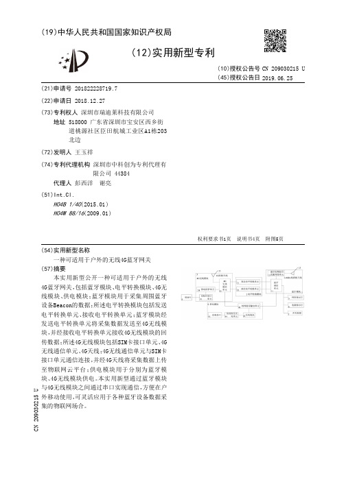
(19)中华人民共和国国家知识产权局(12)实用新型专利(10)授权公告号 (45)授权公告日 (21)申请号 201822228719.7(22)申请日 2018.12.27(73)专利权人 深圳市瑞迪莱科技有限公司地址 518000 广东省深圳市宝安区西乡街道桃源社区臣田航城工业区A1栋203北边(72)发明人 王玉祥 (74)专利代理机构 深圳市中科创为专利代理有限公司 44384代理人 彭西洋 谢亮(51)Int.Cl.H04B 1/40(2015.01)H04W 88/16(2009.01)(54)实用新型名称一种可适用于户外的无线4G蓝牙网关(57)摘要本实用新型公开一种可适用于户外的无线4G蓝牙网关,包括蓝牙模块、电平转换模块、4G无线模块、供电模块;蓝牙模块用于采集周围蓝牙设备Beacon的数据;所述电平转换模块包括发送电平转换单元、接收电平转换单元;蓝牙模块经发送电平转换单元将采集数据发送至4G无线模块,并经接收电平转换单元接收4G无线模块的回传数据;所述4G无线模块包括SIM卡接口单元、4G无线通信单元、4G天线;4G无线通信单元与SIM卡接口单元通信连接,并经4G天线将采集数据上传至物联网云平台;供电模块用于分别为蓝牙模块、4G无线模块供电。
本实用新型通过蓝牙模块与4G无线模块之间通过串口实现通信,方便在户外移动使用,可灵活应用于各种蓝牙设备数据采集的物联网场合。
权利要求书1页 说明书4页 附图5页CN 209030215 U 2019.06.25C N 209030215U1.一种可适用于户外的无线4G蓝牙网关,其特征在于,包括蓝牙模块、电平转换模块、4G无线模块、供电模块;所述蓝牙模块用于采集周围蓝牙设备Beacon的数据;所述电平转换模块包括发送电平转换单元、接收电平转换单元;所述蓝牙模块经发送电平转换单元将采集数据发送至4G无线模块,并经接收电平转换单元接收4G无线模块的回传数据;所述4G无线模块包括SIM卡接口单元、4G无线通信单元、4G天线;所述4G无线通信单元与SIM卡接口单元通信连接,并经4G天线将采集数据上传至物联网云平台;所述供电模块用于分别为蓝牙模块、4G无线模块供电。
平台建设方案

平台建设方案目录一、项目背景与目标 (3)1.1 项目背景 (3)1.2 项目目标 (4)二、平台需求分析 (6)2.1 功能需求 (7)2.2 性能需求 (8)2.3 安全性需求 (9)2.4 可用性需求 (10)三、平台技术选型 (11)3.1 前端技术 (12)3.2 后端技术 (14)3.3 数据库技术 (15)3.4 云计算技术 (17)4.1 系统整体架构 (19)4.2 前端架构设计 (20)4.3 后端架构设计 (22)4.4 数据库架构设计 (24)五、平台功能实现 (25)5.1 用户管理模块 (26)5.2 内容管理模块 (27)5.3 交互功能模块 (28)5.4 数据分析模块 (30)六、平台安全策略 (31)6.1 数据加密 (32)6.2 权限控制 (32)6.3 日志审计 (33)6.4 防火墙与入侵检测 (35)7.1 测试目的 (37)7.2 测试范围 (38)7.3 测试方法 (40)7.4 缺陷管理 (41)八、平台上线与运维 (42)8.1 上线计划 (43)8.2 运维团队 (44)8.3 监控与维护 (46)九、平台推广策略 (47)9.1 目标用户 (49)9.2 推广渠道 (50)9.3 用户反馈机制 (51)十、项目预算与效益评估 (52)10.1 项目预算 (53)10.2 效益评估 (54)10.3 风险评估 (55)一、项目背景与目标随着信息技术的迅猛发展,数字化、网络化、智能化已成为各行业转型升级的关键驱动力。
在此背景下,我们公司决定构建一个全新的平台,以整合公司内外部资源,提升业务效率,增强市场竞争力,并实现公司的长期可持续发展。
本项目旨在打造一个安全、稳定、易用的数字化平台,通过集成先进的信息技术,实现数据的精准采集、高效处理与智能分析,为公司决策提供有力支持。
该平台将作为公司与客户、合作伙伴之间的桥梁,促进信息的顺畅流通,提升客户满意度与合作关系。
PT6000CH 六通道蓝牙音频接收器,多区域音频与麦克风控制系统用户操作指南说明书

Pyle's Bluetooth 6CH Amplifier is the perfect solution for all of your audio needs. Using the latest sound amplification technology and an impressive 600 Watt power output, this receiver is designed to deliver pure 6CH sounds from a wide range of connected music sources. Built-in Bluetooth audio receiver ability allows you to stream your music wirelessly and it works with all of your favorite devices (like Smartphones, Tablets, Laptops, Computers, etc. ) Enjoy full r ange 6CH sound reproduction when streaming audio with a wireless range of up to 30’ feet. Additional system features include FM Radio with LED display, USB Flash Drive Reader, SD Card Reader, (2) 1/4" Microphone Inputs, Binding Post Speaker Terminal connectors, (3)RCA Stereo Inputs, Line Stereo RCA Output, and along with an Aux (3.5mm) jack to connect even more external devices. Take control of your sound with the Pyle PT6000CH Bluetooth Stereo Amp Receiver. Instruction0102High Performance Features:The job of PT6000CH is a power amplifier to deliver clean power to your speakers. PT6000CH with best design and best components can give you a profoundly positive effect on sound quality for your home theater, media room, or whole-house audio system.Design and customize a home theater that fits seamlessly into your home decor, and Multi-channel amps like the PT6000CH incorporate high-efficiency, space-saving digital technology. Or go big with complete, whole-house audio solutions. Whether you want to maximize your home theater experience or transform your living space, PYLE Audio has total solutions to help you get the most out of your movies and music from clean power amplifiers to in-wall and outdoor speakers, subwoofers, custom controls, and more.Rated at 50 watts per channel RMS at 8 ohms, the PT6000CH from PYLE Audio is driving complex audio systems and will distribute sound to 6 different locations without the risk of overload. Equipped with rack-mountable high current amp includes 6 channels (speakers), so owning this amp is like having three Stereo channel amps in one efficient location.Make PYLE Audio as a Part of Your Total Audio SolutionPYLE Audio offers everything you need to design and build a complete home theater solution, customized to your home. In-wall speakers, amplifiers, custom control products, and more are all available to give you the perfect home audio experience, indoors or outdoors.Available For Wall/Ceiling SpeakersLarge cone areas, pivoting drivers, ease of installation and exceptional sound quality make PYLE Audio's line of in-wall and in-ceiling speakers an excellent choice for those who don't want to give up precious floor or shelf space. PYLE Audio offers models with varying features, materials, and cone sizes to fit any application and budget.Available For Outdoor SpeakersMake your next backyard BBQ or swim party special by installing an outdoor speaker system. PYLE Audio offers a huge selection ofaffordable models, from weather-resistant patio speakers to heavy-duty rock speakers that blend into any landscape. PYLE Audio outdoor speakers are built tough and tested under extreme weather conditions to ensure a long and happy life.Available For Audio ControlA whole-house audio system lets you enjoy great sound in every room of your house. Pyle Audio has everything you need for a whole-house system, including volume controls, speaker selectors and IR repeater systems that let you hide your electronics neatly inside a cabinet.So Choose the PYLE Audio Amplifier That's Right for You0506Microphone Talk-Over / Voice Priority Function Front Panel Control Center with Digital LED Display Aux (3.5mm) Audio Input ConnectorConnect & Stream Audio from External Devices USB Flash Drive Reader for Digital Audio File Playback USB Port Doubles as Device Charge Port (2) 1/4'' TRS Microphone Input Jacks(3) Pair RCA (L/R) Aux Audio Input Connectors (6) Pair Speaker Binding Post Output Connectors RCA (L/R) Audio Line Output ConnectorsFeatures:•6-Channel Powered Amplifier Receiver •Multi-Zone Audio Control System•Built-in BT for Wireless Audio Streaming Ability ••••••••••Wireless BT Connectivity:•Works with All of Today’s Latest Devices•(Smartphones, Tablets, Laptops, Computers, etc.)•BT Network Name: ‘BT-RY’•BT Network Password: Not Required •BT Version: 4.0•Wireless Range up to 30’+ ft.Technical Specs:•4200 Watt Maximum Power Output•MAX Power Output: 6-CH x 700 Watt @ 4 Ohm •RMS Power Output: 6-CH x 350 Watt @ 8 Ohm •Frequency Response: 20Hz - 20KHz •Signal to Noise Ratio: ≥81dB •T.H.D.: <0.1%•Radio Station Memory: 30 Station Presets •Digital File-type Compatibility: MP3, WMA •Maximum USB/SD Flash Support: 64GB •Power Supply: 110/240V•Dimensions (L x W x H): 16.9’’ x 11.5’’ x 3.4’’•Unit Weight: 18.07 lbs.•Microphone Talk-Over / Voice Priority Level Control•Independent Channel / Aux Input / Microphone Audio Controls •Audio Input Mode Selectable (BT/USB/SD/FM/AUX)•Built in Short Circuit and Over Voltage Protection •Power ON/OFF Switch •LED Indicator Lights•For Home, Office or Business Use 9.Power On/Off Switch 10.Power On /Off LED11.Separate Channel 1/2/3/4/5/6 Output Volume Control 12.Separate Channel 1/2/3/4/5/6 Output LED Signal The Indicator Lights when the Output is working.13.Power Input14.Power Selector (110V /60Hz or 230V /50Hz 15.FM Antenna 16.BT Antenna17.Speaker Stereo Output Binding Posts 18.Separate MIC1 & MIC2 TRS Inputs19.Separate Stereo AUX 1, AUX2, & AUX 3 RCA Inputs 20.Line Stereo RCA Outputs。
应急通信指挥车方案讲解

应急通信指挥车技术方案目录第一章综述................................................................................................................................ - 1 -1.1 设计思想....................................................................................................................... - 1 -1.2 设计原则....................................................................................................................... - 3 -1.3 建设目标....................................................................................................................... - 3 -1.4 主要功能....................................................................................................................... - 4 -1、通信功能................................................................................................................ - 4 -2、图像采集、处理和传输功能................................................................................ - 4 -3、广播功能................................................................................................................ - 4 -4、照明功能................................................................................................................ - 4 -5、会议功能................................................................................................................ - 4 -6、供配电功能............................................................................................................ - 4 -第二章总体设计........................................................................................................................ - 6 -总体框架和总体拓扑示意图.............................................................................................. - 6 -2.1 无线图像传输系统....................................................................................................... - 7 -2.1.1 TFDM单兵式/密拍式无线图像传输设备传输流程........................................ - 7 -2.1.2 TFDM车载式无线图像传输设备传输流程................................................... - 10 -2.1.3 便携式3G公网无线图像传输设备传输流程 ............................................... - 12 -2.1.3 车载式3G公网无线图像传输设备传输流程 ............................................... - 15 -2.2 照明系统..................................................................................................................... - 18 -2.4 供配电系统................................................................................................................. - 20 -2.4.1 发电机.............................................................................................................. - 21 -2.4.2 APC不间断电源在线式5KV(C3KS)........................................................ - 22 -2.4.3 配电系统设计.................................................................................................. - 23 -2.5 安全警示系统........................................................................................................... - 23 -2.6 其他及辅助系统......................................................................................................... - 23 -2.6.1 广播系统.......................................................................................................... - 23 -第三章车辆改制...................................................................................................................... - 26 -3.1 原车外观与参数......................................................................................................... - 26 -3.2 外观效果图................................................................................................................. - 26 -3.3 总体布局图................................................................................................................. - 27 -3.4 整车配重..................................................................................................................... - 28 -3.5 设备减振..................................................................................................................... - 28 -3.6 系统的可维修性......................................................................................................... - 28 -3.7 设备及人员安全......................................................................................................... - 28 -3.8 电磁干扰(EMC)的解决 ........................................................................................ - 29 -3.9 车内装饰..................................................................................................................... - 29 -3.10 表面处理................................................................................................................... - 30 -3.11 车辆密封................................................................................................................... - 30 -3.12 隔音隔热................................................................................................................... - 30 -第四章设备配置列表......................................................................................错误!未定义书签。
DCP680 八通道汽车DSP音频处理器说明书

DCP680 主机
1台
ห้องสมุดไป่ตู้
线控器
1个
用户手册/保修卡
1 本/1 张
5 米 USB3.0 连接线
1条
光盘
2张
蓝牙天线
1只
Wifi 天线
1只
目录
用户手册
一、 注意事项 .................................................................1 二、 产品简介 .................................................................2
目录
用户手册
⑴ 加载机器预置场景 .............................................33 ⑵ 另存为机器预置场景 ...........................................34 ⑶ 删除机器预置场景 .............................................35 ⑷ 加载电脑上场景文件 ...........................................36 ⑸ 另存为电脑上场景文件 .........................................36 ⑹ 加载整机场景.................................................37 ⑺ 保存整机场景.................................................37 7.8.2、选项菜单 .....................................................37 ⑴ 中英文切换设置...............................................37 ⑵ 高级设置.....................................................38
华为交换机路由器常见开局配置指导

华为交换机路由器常见开局配置指导 5.3 配置网络互连互通 ..................................................... 51 5.3.1 通过快速向导配置实现上网 .......................................... 51 5.3.2 配置静态 IP 地址上网 .............................................. 56 5.3.3 配置 PPPoE 拨号上网 .............................................. 59 5.4 配置 DHCP 服务器 ..................................................... 61 5.5 映射内网服务器....................................................... 62 5.6 限速配置............................................................ 64 5.6.1 基于 IP 地址限速 ................................................. 65 5.6.2 基于内网用户限速................................................. 66 5.7 公网多出口配置....................................................... 69 5.7.1 基于源地址的多出口 ............................................... 69 5.7.2 基于目的地址的多出口 ............................................. 73 6 常见网络故障维护方法 ...................................................... 76 6.1 删除多余配置 ........................................................ 76 6.2 密码恢复............................................................ 77 6.2.1 Console 密码恢复 ................................................ 77 6.2.2 Telnet 密码恢复 ................................................. 77 6.2.3 Web 密码恢复.................................................... 77 6.3 信息采集............................................................ 77 6.4 本地端口镜像配置 ..................................................... 82 6.5 流量统计配置 ...................................................局配置指导
华为ECC应急指挥解决方案彩页
自然灾害
卫生事件
1
事故灾难 社会公共安全事件
华为企业ICT解决方案 悉您所需 为您所用
华为eSpace应急指挥解决方案
以统一的接处警中心、可视化的指挥调度、智能决策分析与灾难响应系统为核心,结合LBS、GPS、GIS、远程协同指挥 等先进ICT能力,实现应急指挥中心与应急指挥现场的高效联动,最终使得警情/灾情得以及时、有效处置,减少民众的生 命和财产损失。
固定监控设备
无线监控设备 车载监控设备
2
华为企业ICT解决方案 悉您所需 为您所用
解决方案典型组网
应急指挥中心
CAD接处警平台
GIS/GPS
智能分析服务器
灾难管理 预案调度
解码器/拼接器
辅助决策 有无线统
CTI
视频监控 视频会议
预测预警 一调度机
PSTN/PLMN/ NGN/3G
客户价值 yy 指挥网络化、应急信息化、执行程序化、决策智能化 yy 优化资源配置,提升事故处置方案和综合救援能力 yy 提升应急指挥效率,满足不断提升的安全需要
9
华为企业ICT解决方案 悉您所需 为您所用
老挝警察指挥中心
客户需求
yy 首都万象人口密集,成分复杂,案件多发,因此需要建立快速响应的调度 网络
指挥大厅
多屏录播
智真决策
决 策 指 挥 层
MDB协同标绘
VS/PBX/GIS/… IVS 监控平台
监控
移动应急
融
合
层
融合媒体网关 MCU
SMC 可视调度台 多屏录制系统 录播服务器
TCS 应急决策平台
IP/E1/4E1/3G/PSTN/卫星/微波
接 入 层
华为视频会议解决方案

华为高清视讯系统技术方案建议书临时方案华为技术有限公司2016年10月9日使用说明(2016.10.9):1、模板使用时根据实际客户需求和方案设计,选择相应章节内容,与实际方案不相关的内容需删除;2、模板中使用说明、备注部分为内部参考,具体制作面向客户提交的方案时,需删除所有使用说明、备注部分。
目录1视讯技术发展及应用需求 (5)1.1技术发展 (5)1.1.1视频 (5)1.1.2音频 (5)1.1.3组网 (5)1.2应用需求 (6)1.2.1高临场感体验 (6)1.2.2低带宽高清 (6)1.2.3良好的网络适应性 (6)1.2.4良好的易用性 (6)1.2.5稳定性和可维护性 (7)1.2.6标准开放和融合互通 (7)1.2.7支持多种线路接入方式 (7)1.2.8客户化、可定制 (7)2华为高清视讯系统需求分析 (7)2.1华为背景简介 (7)2.2华为网络现状分析 (8)2.3华为客户需求分析 (8)3 华为高清视频系统设计方案建议 (8)3.1系统设计依据 (8)3.2系统设计原则 (11)3.3方案四SMC2.0+MCU96X0 ................................................................... 错误!未定义书签。
3.4系统组网方案四配置清单 ...................................................................... 错误!未定义书签。
4华为高清视频系统主要功能及特点 (12)4.1良好的高清晰音视频沟通体验 (12)4.1.1全高清108060端到端解决方案 (12)4.1.2高流畅性 (12)4.1.3强大全编全解处理能力,最大限度支持动态速率、协议适配 (13)4.1.4VME+H.264 HP 低带宽高清 (13)4.1.5H.264 SVC技术 (14)4.1.6高清1080P60FPS静态/动态双流 (14)4.1.7高保真,立体声,CD音质效果 (15)4.2丰富的会议召集模式 (15)4.2.1主叫呼集 (15)4.2.2匿名会议(电话会议模式) (16)4.2.3管理员调度 (16)4.2.4网络预约 (16)4.2.5视音频IVR导航与ad-hoc创建和加入会议 (16)4.2.6特服号入会 (16)4.2.7Outlook预约会议 (16)4.2.8云化资源池管理实现会议智能调度 (16)4.3良好的网络适应性 (18)4.3.1超强纠错(SEC 2.0-- Super Error Concealment) (18)4.3.2超强纠错(SEC 3.0-- Super Error Concealment) (18)4.3.3智能调速(IRC--Intelligent Rate Control) (19)4.3.4断线恢复(RoD--Reconnect on Disconnect) (19)4.3.5丢包重传(ARQ--Automatic Repeat reQuest) (20)4.4简单易用 (20)4.4.1用户界面简约时尚 (20)4.4.2PAD智能操控平台 (20)4.4.3丰富的会议控制功能 (20)4.4.4会议模板预置功能 (21)4.4.5字幕与横幅功能 (22)4.4.6一屏三显,节约投资 (22)4.4.7多视一流功能 (22)4.4.8无线辅流,轻松共享数据 (23)4.4.9支持WIFI呼叫及无线麦克 (23)4.4.10USB零配置 (24)4.4.11全景会场功能 (25)4.4.12多组多画面(on-table多画面) (25)4.4.13图形化操作界面 (25)4.4.14软终端随时随地接入会议 (26)4.4.153G-SDI接口实现1080P60fps远距离传输 (28)4.5安全稳定 (28)4.5.1产品成熟 (28)4.5.2系统稳定 (29)4.5.3多重加密 (30)4.5.4系统安全 (30)4.5.5资源池会议备份 (32)4.6管理维护方便 (33)4.6.1分级分权,大网维护简单 (33)4.6.2Nlog网络线路实时监控 (37)4.6.3支持WEB管理 (37)4.6.4系统设备拓扑图生成管理 (37)4.6.5系统设备配置批量升级及备份 (37)4.6.6系统告警和日志管理 (38)4.7标准互通 (39)4.7.1采用国际标准协议 (39)4.7.2支持TIP协议,与思科网真互通 (39)4.7.3华为视讯产品互联互通能力介绍 (39)4.7.4支持与微软UC系统互通 (41)4.7.5端到端IMS融合解决方案 (42)4.8丰富组网 (42)4.8.1支持多种接入方式 (42)4.8.2最大5级和超强多通道级联能力 (43)4.8.3支持大容量语音接入,满足在外人员接入视频会议需求 (43)4.8.4支持高清录制点播功能 (44)4.8.5支持软件化部署的管理平台 (48)4.8.6完善的公私网穿越解决方案 (49)4.9专业定制 .................................................................................................. 错误!未定义书签。
- 1、下载文档前请自行甄别文档内容的完整性,平台不提供额外的编辑、内容补充、找答案等附加服务。
- 2、"仅部分预览"的文档,不可在线预览部分如存在完整性等问题,可反馈申请退款(可完整预览的文档不适用该条件!)。
- 3、如文档侵犯您的权益,请联系客服反馈,我们会尽快为您处理(人工客服工作时间:9:00-18:30)。
FreescaleMPC5668G汽车网关解决方案汽车网关汽车网关汽车网关和车体控制模块和中央网关.本文介绍了MPC5668x主要特性,方框图以及MPC5668G评估板(EVB)主要特性和详细电路图.Electronic content in vehicles keeps increasing. A number of different communication protocols, including consumer protocols making their way into the automotive market, keep these electronic components working together.The 32-bit Qorivva MPC5668G MCU, built on dual core Power Architecture® technology, connects all the possible communication protocols you can find in a car at one single point. The dual-core architecture provides the performance throughput needed to maintain real-time operation backed-up by a strong third-party ecosystem support.MPC5668x主要特性:• 32-bit CPU core complex (e200z650)– Compliant with Power Architecture embedded category– 32 KB unified cache with line locking and eight-entry store buffer16– Execution speed static to 116 MHz• 32-bit I/O processor (e200z0)– Execution speed static to 1/2 CPU core speed (58 MHz)• 2 MB on-chip flash– Supports read during program and erase operations, and multiple blocks allowing EEPROM emulation• 512 KB + 80 KB (592 KB) on-chip ECC SRAM (MPC5668G)• 128 KB on-chip ECC SRAM (MPC5668E)• 16-entry Memory Protection Unit (MPC5668E only)• Direct memory access controller– 16-channel on MPC5668G– 32-channel on MPC5668E• Fast ethernet controller– Supports 10-Mbps and 100-Mbps IEEE 802.3 MII, 10-Mbps 7-wire interface– IEEE 802.3 MAC (compliant with IEEE 802.3 1998 edition)• Media Local Bus (MLB) interface (MPC5668G only)– Supports 16 logical channels, max speed 1024 Fs• Interrupt controller (INTC) supports 316 external interrupt vectors (22 are reserved)• System clocks– Frequency-modulated phase-locked loop (FMPLL)– 4 – 40 MHz crystal oscillator (XTAL)–32 kHz crystal oscillator (XTAL)– Dedicated 16 MHz and 128 kHz internal RC oscillators• Analog to Digital Converter (ADC) module– 10-bit A/D resolution– 32 external channels– 36 internal channels (MPC5668G)–64 internal channels (MPC5668E)• Cross-Triggering Unit (MPC5668E only)– Internal conversion triggering for ADC– Triggerable by internal timers or eMIOS200• Deserial Serial Peripheral Interface (DSPI)– Four individual DSPI modules– Full duplex, synchronous transfers– Master or slave operation• Inter-IC communication (I2C) interface– Four individual I2C modules– Multi-master operation• Serial Communication Interface (eSCI) module– Two-channel DMA interface– Configurable as LIN bus master• eMIOS200 timed input/output– 24 channels, 16-bit timers (MPC5668G)– 32 channels, 16-bit timers (MPC5668E)• Controller Area Network (FlexCAN) module– Compliant with CAN protocol specification, Version 2.0B active–64 mailboxes, each configurable as transmit or receive• Dual-channel FlexRay controller– Full implementation of FlexRay Protocol Specification 2.1, RevA– 128 message buffers• JTAG controller (MPC5668G only)– Compliant with the IEEE 1149.1-2001• Nexus Development Interface (NDI)– Available in 256 MAPBGA package only– Compliant with IEEE-ISTO 5001-2003– Nexus class 3 development support on e200z650– Nexus class 2+ development support on e200z0• Internal voltage regulator allows operation from single3.3V or 5 V supplyMPC5668x目标应用:Automotive GatewaysBody Control Module and Central Gateway图 1.MPC5668G方框图图 2.MPC5668E方框图MPC5668G评估板(EVB)This user’s manual details the setup and configuration of the Freescale Semiconductor MPC5668 Evaluation Board (hereafter referred to as the EVB). The EVB is intended to provide a mechanism for easy customer evaluation of the MPC5668 family of microprocessors, and to facilitate hardware and software development.At the time of writing this document, the MPC5668 family is offered in a 208MAPBGA package. A 256MAPBGA package supporting Nexus debug is also available for development purposes.The EVB is intended for bench / laboratory use and has been designed using normal temperature specified components (+70°C).图3. MPC5668G评估板(EVB)外形图MPC5668G评估板(EVB)主要特性:The EVB provides the following key features:• MCU Socket supporting the 208BGA production package and the 256BGA development package.• Single 12-14V external power supply input with on-board regulators to provide all of the necessary EVB and MCU voltages. Power may be supplied to the EVB via a 2.1mm barrel style power jack or a 2-way level connector. 12V operation allows in-car use if desired.• Flexible on-board power supply configuration with the option to bypass the internal MCU regulators if desired.• Master power switch and regulator status LED’s – Regulators connected to the ADC to allow monitoring.• User reset switch with reset status LED’s• User configurable Low Voltage Inhibit to monitor the status of the 3.3V and 5V regulators.• Control of the BOOTCFG status via a dedicated jumper.• Flexible MCU clocking options:_ 40MHz Oscillator Crystal_ 32Khz Watch Crystal_ SMA connector to allow external clock support_ 8Mhz Oscillator circuit.• SMA connector on MCU-CLKOUT signal for easy access.• Standard 14-pin ONCE debug connector and 38-pin MICTOR Nexus connectors.• All MCU signals are accessible on port-ordered groups of 0.1” pitch headers.• DSPI A signals can be routed to a set of shift registers to allow a 32-bit phantom port to be created.• SCI channels A and B can be routed to a standard DB9 female connector (PC RS-232 compliant) via a Maxim physical interface.• SCI channels C and D can be routed to LIN interface header (0.1”) and molex connectors, both will full physical transceivers.• FlexCAN channels A and B can be routed to 0.1” headers and DB9 connector via a Philips high speed CAN transceiver which supports both 3.3V and 5V inputs.• FlexCAN channels C, D, E and F are routed to the prototyping area with DB9 connectors to allow additions CAN physical interfaces to be easily integrated.• User prototyping area consisting of a 0,1” grid of through hole pads with easy access to the EVB ground and power supply rails.• Ethernet signals routed to a National Semiconductor physical interface and Pulsejack RJ45 connector with integrated magnetics.• MLB signals routed to SMSC MOST INIC with Tyco Optical Transceiver. INIC JTAG and MLB monitor ports. Support for optional ROM INIC or MLB150 daughter card from SMSC.• 4 active low LED’s and 4 pushbutton switches for development purposes.• Jumper selectable variable resistor connected to ADC channel 0, driving between VRH and VRL.• Liberal scattering of GND test points (surface mount loops) placed throughout the EVB.图4.MPC5668G评估板(EVB)功能框图图5.MPC5668G评估板(EVB)电路图(1)图6.MPC5668G评估板(EVB)电路图(2)图7.MPC5668G评估板(EVB)电路图(3)图8.MPC5668G评估板(EVB)电路图(4)图9.MPC5668G评估板(EVB)电路图(5)图10.MPC5668G评估板(EVB)电路图(6)图11.MPC5668G 评估板(EVB)电路图(7)图12.MPC5668G评估板(EVB)电路图(8)图13.MPC5668G评估板(EVB)电路图(9)图14.MPC5668G评估板(EVB)电路图(10)图15.MPC5668G评估板(EVB)电路图(11)图16.MPC5668G评估板(EVB)电路图(12)图17.MPC5668G评估板(EVB)电路图(13)图18.MPC5668G评估板(EVB)电路图(14)图19.MPC5668G评估板(EVB)电路图(15)图20.MPC5668G 评估板(EVB)电路图(16)图21.MPC5668G评估板(EVB)电路图(17)详情请见:/files/32bit/doc/data_sheet/MPC5668x.pdf?pspll=1和/files/32bit/doc/user_guide/MPC5668GKITUM.pdf?fpsp=1以及/files/microcontrollers/hardware_tools/schematics/MPC5668GKIT_SCH.pdf?fpsp=1。