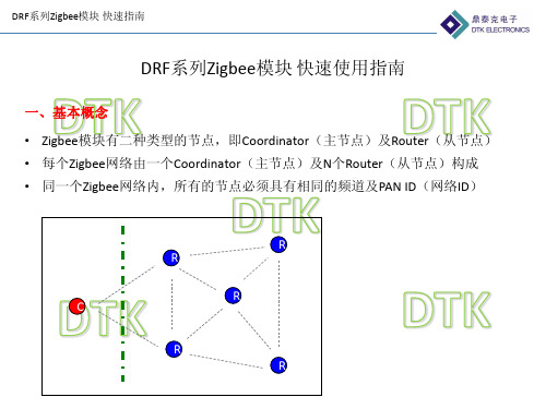
DRF系列ZigBee模块数据传输指南
zigbee数传电台是怎么进行数据传输

zigbee数传电台是怎么进行数据传输
为了让用户能快速熟悉E180-DTU和E18-DTU系列zigbee DTU数传电台,该4G DTU数传电台是基于zigbee3.0技术的zigbee数传电台,前文介绍了zigbee数传电台如何结合上位机软件建立zigbee网络和加入zigbee网络的快速入门教程,包括节点类型配置、PANID设置、信道设置、发射功率设置。
本文接着介绍zigbee数传电台数据传输过程是怎么进行配置和数据传输原理:
(1)打开协调器设备和入网设备的上位机软件,点击“读取参数”,确认设备当前网络状态为“connect”, 表示设备已组网。
(2)点击“查询”,查询设备的串口配置参数。
设备的默认串口波特率115200,透传目标短地址为0xFFFF,目标端口0xFF(即255),即设备在透传模式下默认为广播。
(3)然后设置路由器设备采用点播的形式向协调器设备透传数据,协调器设备采用广播模式透传。
在路由器设备的上位机界面中,把目标短地址设置成00 00(即0x0000),目标端口设置成01(即0x01 或1),然后点击“设置”。
设置完毕后可再次点击“查询”确认是否设置成功。
(4)进入透传模式,分别在协调器设备和路由器设备的上位机界面点击“进入传输模式”后,二者均可进入透传模式。
一方串口输入任何数据,另一方串口皆可完全输出相同数据。
进入透传模式后,关闭上位机配置软件,打开串口助手。
在任意一方输入任何数据,另一方都会输出相同数据。
发送数据的一方每次发送数据后会返回"OK"表示发送成功,返回"FAIL"或者"ERRO"表示发送失败。
Digi International ZigBee 网络设备云数据传输指南说明书
A Beginner’s guide to send data to Device Cloud from a ZigBeeNetwork1 Document HistoryDate Version Change Description Author12 Sep 14 1.0 Initial Release Ankur Mathur2 Table of Contents1Document History (2)2Table of Contents (3)3Introduction (4)3.1Outline (4)3.2Audience (4)3.3Assumptions (4)3.4Scope (4)4Setting up network between XBee and gateway (5)5Connecting gateway to Device Cloud (8)6Running python script on gateway (10)7Conclusion (12)8Useful Software Links: (12)3 Introduction3.1 OutlineA getting stated guide for people to create basic setup for sending data from a ZigBee network to Etherios Device Cloud.3.2 AudienceThis guide has been written for users with a basic understanding of XBee modules, Digi ConnectPort gateways and Etherios Device Cloud.This application note applies only to ZigBee or DigiMesh network of module(s) and Connect Port X2/X4/X2e gateway.3.3 AssumptionsThis document assumes that devices are set to their factory default configurations.3.4 ScopeThis document will cover aspects of setting up a network for data transmission to Device Cloud using a Python Script. It does not teach Python Programming.4 Setting up network between XBee and gateway4.1 Configuring gatewayPlug in your ConnectPort gateway to network and accessing its Web UI using appropriate IP address. You can find gateway using Digi’s “Device Discovery” Tool (refer section 8). In Gateway’s Web UI, navigate to XBee network->Configuration. Select Coordinator from Network View of XBee Devices. Enter appropriate Extended PAN ID (ID) parameter and click “Apply” button at end.The above step will initiate a ZigBee network with the specified PAN ID.4.2 Configuring XBee modulePlace XBee module on Digi’s XBIB Dev board and connect to PC.Open XCTU and select appropriate COM port to load module’s current configuration. Make sure that module is not acting as Coordinator. If so, load modules with Router or End Device firmware (ZigBee Router AT recommended). There can be only one coordinator in a ZigBee network, which is Connect Port gateway in this case.Set the same PAN ID that you have used to create a ZigBee network. This is required to make sure that module will join network created by ConnectPort gateway. PAN ID can be set by providing appropriate value in white box next to its entry. Click “Write” button to save the modifications made.If both ConnectPort gateway and XBee module are in vicinity of each other, then module will connect to gateway’s coordinator in few seconds.You can verify it by observing “Association LED” (Red light) on XBIB interface board which will start blinking once module successfully joins a network.Alternate method is to check Operation 16-bit PAN ID parameter on both devices. If they have same hex values, then you have successfully setup a network between ConnectPort gateway and XBee module.How to set up destination address parameter?Provide coodinator’s mac address i.e. its SH and SL parameter to module’s DH and DL parameter respectively. You can also provide coordinator’s alias address i.e.0x0000000000000000 (default value on Router AT firmware) as well to these fields. See below image for reference:5 Connecting gateway to Device CloudNow we need to create a communication link between ConnectPort gateway and Etherios Device Cloud.In ConnectPort gateway Web UI, navigate to “Device Cloud” under “Configuration”. Provide appropriate URL as shown below and click “Apply”.For US Cloud: ---------------------------------------------------For UK Cloud: Make sure you have an active account on Device Cloud. If not, then you can create a new one by visiting below provided web link:https:///Browse to respective cloud URL in browser and navigate to Device Management->Device tab present on top of window. Click Add devices button and follow the options to add your gateway to device cloud.Visit below provided link to learn configuring and troubleshooting ConnectPort gateway for Connection to the Device Cloud:/support/kbase/kbaseresultdetl?id=3186Now gateway is added to Device Cloud.If gateway is properly configured Device Cloud will how added device as Connected and a Connected blue symbol will appear, if not connected it will be in red color.6 Running python script on gatewayYou need a python script running on ConnectPort gateway that redirects all incoming data from XBee module(s) to Device Cloud it is connected to.A python file for this purpose is available at below provided link:/wiki/developer/index.php/XBee_to_Device_Cloud_-_DataPoint_CreationThis script encodes data in Base64 format to add security for uploaded information. Add that script onto ConnectPort gateway and enable auto-start.To do so, open Web UI of ConnectPort gateway and navigate to Applications->Python. Upload above script to gateway by following steps.Click on Choose File and point to the respective python script and click upload.Now, click on the “Auto-start Settings” section. Here, specify script name to auto-start it after every gateway reboot. See below screenshot for reference:Click “Apply” and reboot gateway by navigating to “Administration” section.You can use “Terminal” tab of XCTU connected with XBee module to transmit data from XBee module to XBee Coordinator sitting inside gateway.If configured correctly, gateway will redirect all incoming data packets from Zigbee network to Device Cloud. In Device Cloud’s Web UI, this data will be available under Data Services Data Streams.7 ConclusionYou have now successfully created a communication link between Device Cloud to ConnectPort gateway to XBee module and have successfully transmitted data from XBee module to Device Cloud.8 Useful Software Links:•Device Discovery Tool:/support/getasset?fn=40002265&tp=5•X-CTU : /support/productdetail?pid=3352&type=utilities。
zigbee网络中的信息传输方式

Zigbee网络中的消息传输方式1、广播广播是zigbee网络中的一种数据传输方式,它是由网络中的一个节点向其它节点发送消息的过程。
在zigbee网络中协调器,路由器和macRxOnWhenIdle域值为TRUE的终端设备可以参与广播转发,其余节点不参与。
能够接受广播帧的目的节点由广播帧中的目的地址来确定,不同的广播地址及其对应接收节点类型如下表所示:在所有参与广播的节点中都需要维护一个包含若干条广播事务记录(Broadcast Transaction Rcord,BTR)的广播事务表(Broadcast Transaction Table,BTT),该表用来记录哪些节点已经成功转发了广播帧。
一个节点接收到一个广播帧时首先检查帧中的目的地址和自己的设备类型是否相符。
不相符则丢弃;相符的话设备从本地BTT中查找相应的BTR,若干存在,则对其进行更新;若不存在,则检查BTT 中是否有空的或者过期的BTR项。
如果没有,则丢弃广播帧;若有则添加新的BTR项并将广播帧提交到高层进行处理。
若节点属性中radius值不为0或者该设备不是终端设备则转发该帧。
BTT表中每个BTR都有有效期,在有效期过后,设备会将该BTR定义为失效以便后续写入新的BTR。
MAC PIB属性macRxOnWhenIdle值为FALSE的zigbee路由器接收到广播帧后将会以单播的形式将该帧发送到其邻居节点。
如果一个节点接收到一个广播帧后节点查找BTT中的广播帧序列号发现其另外一个邻居已经广播了该帧,则节点将忽略该广播帧。
为了方便重发广播帧,每个zigbee路由器的NWK层至少能够缓存1帧数据。
Zigbee中广播的主要用于路由发现。
广播过程如下图所示:2、组播组播就是针对zigbee网络的某个固定群组进行消息传送。
在zigbee网络中将多个节点在同一个Group ID下注册,从而使其逻辑上形成一个群组。
当针对该组传送数据帧,只有组内的所有节点都能够接收该帧。
ZigBee无线模块说明书

Coordinator 或Router 不能大于模块间组网的最大距离。
-5-
演示与测试 当通过调试软件向网络中其中任意一个模块的串口发送数据时,你可
以在网络中其它所有模块的串口上接收到相同的数据,这表明ZigBee 网络 运行正常。 注意事项
基于ZigBee 的原因,每次向串口发送的数据长度不要多于70 个字节。 过快地通过串口向模块发送数据可能会造成数据丢失。 Zigbee网络
ZigBee 无线模块使用说明书 一、 概述
该模块是一款基于 ZigBee 标准协议的微功率无线数传模块。基于该模块 开发的无线产品可用于各种智能仪表;家庭智能控制装置;安防、报警;酒店、 机房设备无线监控,门禁系统,人员定位;交通、路灯控制;物流、有源 RFID、 POS 系统,无线手持终端;工业遥控、遥测,自动化数据采集;无线传感网络 等。 Zigbee微功率无线数传模块特点 开放频段,无需申请频点,载频频率2.4GHz; 高抗干扰能力和低误码率,基于O-QPSK 的调制方式,采用高效前向纠
2
P00
ADC 输入第 0 通道,和通用 Pin19
输入输出口复用。
3
P01
ADC 输入第 1 通道,和通用 Pin18
输入输出口复用。
4
P02
ADC 输入第 2 通道串口支持 Pin17
UART 和 SPI 两种模式
5
P03
ADC 输入第 3 通道串口支持 Pin16
-2-
UART 和 SPI 两种模式
调制方式 工作频率 发射功率 传输距离 接收灵敏度 发射电流
O-QPSK 2.40~2.4835GHz
≧18dBm 700m -94dBm
≦166mA
wifi to rs232快速指南
3
2 4
1
Router没加入网络之前,PAN ID 读出来为FF FE 短地址读出来为:FF FE
4
模块重启后,上述参数设置生效。
DRF系列Zigbee模块 快速指南
特别注意:ROUTER在没有加入网络之前,PAN ID与短地址读出来都是FF FE,加入网络 后才有具体的值,据此可判定ROUTER加入了哪个网络,短地址是多少。
DRF系列Zigbee模块 快速指南
为什么我的Zigbee模块(Router)只能加入6个?
C
R1
R2 R3 R4 R5
R6
因为每个Zigbee节点最多只能为另外6个 节点分配地址,如果每次只设定一个Router 并加入网络,则Coordinator只能直接为6个 Router分配地址.
如果第7个Router要加入网络,则只要保持 前面的6个节点任意一个上电,则第7个即 可加入网络
3
4
1
4
DRF系列Zigbee模块 快速指南
二、组网、使用流程 2,依次将其它模块设定为Router, 并设置PAN ID,频道等参数
1 2
将模块的节点类型设置为Router, 出厂默认,可以不设
3
将模块的频道设置为20,11 -26可 选
将模块的PAN ID设置为12 34. PAN ID从 0001 – FF00可自行设置
R
R
R
C R
R
DRF系列Zigbee模块 快速指南
二、组网、使用流程 1,将某个模块设定为Coordinator, 并设置PAN ID,频道等参数 1
将模块的节点类型设置为 Coordinator
3
2
将模块的频道设置为 20,பைடு நூலகம்1 -26可选 2
ZigBee数据传输实验例程手册
写入的数据 背光
复位信息(低电平复位) 读写控制(高电平为读操作,低电平为写操作 ) 片选择信号,低电平有效 使能控制角,高电平有效 电源
三、操作说明及现象
根据部分二的实验条件,准备好后,连接计算机,准备下载程序。 3.1、 广播、组播、点对点、加入与退出组 步骤一 打开实验中的 ZStack-1.4.3-1 例子,编译 CoordinatorEB,编译成 功后 ,选 择 Project 菜单中的 Debug 选项,下载程序到一个设备。下载成功后,重新启动设备(这个设备将作 为 协 调 器 运 行 )。 重新启动后,设备将会建立网络,建立成功后,显示屏上显示如下字样:
4.1、寻址方式......................................................................................................................... 4 4.1.1、地址类型(Address types)....................................................................................... 4 4.1.2、网络地址分配(Network address assignment)........................................................4 4.1.3、Z-Stack 寻址(Addressing in z-stack).................................................................... 5 4.1.3.1、单点传送(Unicast).......................................................................................5 4.1.3.2、间接传送(Indirect)...................................................................................... 6 4.1.3.3、广播传送(broadcast)....................................................................................6 4.1.3.4、组寻址(Group Addressing)..........................................................................6 4.1.4、重要设备地址(Important Device Adresses).......................................................... 6
zigbee无线通信模块通信流程
zigbee无线通信模块通信流程下载温馨提示:该文档是我店铺精心编制而成,希望大家下载以后,能够帮助大家解决实际的问题。
文档下载后可定制随意修改,请根据实际需要进行相应的调整和使用,谢谢!并且,本店铺为大家提供各种各样类型的实用资料,如教育随笔、日记赏析、句子摘抄、古诗大全、经典美文、话题作文、工作总结、词语解析、文案摘录、其他资料等等,如想了解不同资料格式和写法,敬请关注!Download tips: This document is carefully compiled by theeditor.I hope that after you download them,they can help yousolve practical problems. The document can be customized andmodified after downloading,please adjust and use it according toactual needs, thank you!In addition, our shop provides you with various types ofpractical materials,such as educational essays, diaryappreciation,sentence excerpts,ancient poems,classic articles,topic composition,work summary,word parsing,copy excerpts,other materials and so on,want to know different data formats andwriting methods,please pay attention!深入理解Zigbee无线通信模块的通信流程Zigbee,一种基于IEEE 802.15.4标准的低功耗、短距离、无线通信技术,广泛应用于物联网、智能家居等领域。
深圳市鼎泰克电子 ZigBee 模块说明书
ZigBee模块用户手册V1.4深圳市鼎泰克电子有限公司地址:深圳市宝安区宝安大道卡罗大厦2A栋505-506室电话:0755-******** 29080900E-Mail:yihua@网址:目录一,ZigBee概述二,DRF系列ZigBee模块的特点三,DRF系列ZigBee模块的参数四,DRF系列ZigBee模块的组网五,DRF系列ZigBee模块的数据传输六,DRF系列ZigBee模块的设置一、ZigBee概述(以下内容引自:百度百科,/view/117166.htm)什么是ZigBeeZigBee是IEEE 802.15.4协议的代名词。
根据这个协议规定的技术是一种短距离、低功耗的无线通信技术。
这一名称来源于蜜蜂的八字舞,由于蜜蜂(bee)是靠飞翔和“嗡嗡”(zig)地抖动翅膀的“舞蹈”来与同伴传递花粉所在方位信息,也就是说蜜蜂依靠这样的方式构成了群体中的通信网络。
其特点是近距离、低复杂度、自组织、低功耗、低数据速率、低成本。
主要适合用于自动控制和远程控制领域,可以嵌入各种设备。
简而言之,ZigBee就是一种便宜的,低功耗的近距离无线组网通讯技术。
ZigBee的起源ZigBee, 在中国被译为"紫蜂",它与蓝牙相类似.是一种新兴的短距离无线技术. 用于传感控制应用(sensor and control).此想法在IEEE 802.15工作组中提出,于是成立了TG4工作组,并制定规范IEEE 802.15.4.2002年,ZigBee Alliance成立.2004年,ZigBee V1.0诞生.它是ZigBee的第一个规范.但由于推出仓促,存在一些错误.2006年,推出ZigBee 2006,比较完善.2007年底,ZigBee PRO推出ZigBee的底层技术基于IEEE 802.15.4.物理层和MAC层直接引用了IEEE 802.15.4在蓝牙技术的使用过程中,人们发现蓝牙技术尽管有许多优点,但仍存在许多缺陷。
Zigbee模块
Zigbee模块型号:DRF1605H,主要功能:串口(UART)转Zigbee无线数据透明传输(与DRF1605 PIN脚完全兼容,传输距离1.6公里)(模块出厂默认设置为Router,用户可自行切换为Coordiantor)Zigbee模块主要特点自动组网:所有的模块上电即自动组网,网络内模块如掉电,网络具自我修复功能数据传输:通过串口即可在任意节点间进行数据传播:1,数据透明传输:Coordinator从串口收到的数据会自动发给所有的节点;某个节点从串口收到的数据会自动发送给Coordinator;2,指令方式,任意节点间数据传输:数据传输的格式为:0xFD(数据传输命令)+ 0x0A(数据长度)+ 0x73 0x79(目标地址)+ 0x01 0x02 0x03 0x04 0x05 0x06 0x07 0x08 0x09 0x10(数据,共0x0A Bytes)。
简单易用:用户不用考虑ZigBee协议,像使用串口线一样使用无线模块该模块可配合USB底板使用,无需外部供电,USB口供电及数据传输(USB转串口),强烈建议购买DRF1605H Zigbee模块时,购买至少1片USB底板,以便于调试及配置模块。
该模块可配合RS485底板使用,将DRF1605H的UART口传换成标准的半双工RS485接口,可直接连接到RS485设备(PIN脚与DRF1605完全兼容,下图为DRF1605实拍照片)。
DRF1605H的管脚间距是标准的2.54或2.54*n,所以可以直接插在万用板上使用,便于开发(PIN 脚与DRF1605完全兼容,下图为DRF1605实拍照片)。
DRF1605H与MCU很方便的连接,全面支持51,ARM,X86,MIPS....等内核MCU,只要MCU有串口即可:Zigbee模块参数输入电压标准:DC 3.3V,范围:2.6V-3.6V温度范围-40℃~85℃净重7.4g串口速率38400bps(默认),可设置9600bps, 19200bps, 38400bps, 57600bps, 115200bps无线频率 2.4G(2460MHz),用户可通过串口指令更改频道(2405MHz – 2480MHz,步长:5MHz)无线协议Zigbee2007传输距离可视,开阔,传输距离1600米工作电流发射:120mA(最大),80MA(平均),接收:45mA(最大)待机:40MA(最大)接收灵敏度-110 dBm主芯片CC2530F256,256KFLASH,TI公司最新一代ZigBee SOC芯片可配置节点可配置为Coordinator,Router出厂默认值为:Router,PAN ID=0x199B,频道=22(2460MHz)接口UART 3.3V TX – RX内置RS485方向控制,可直接驱动RS485芯片可直接驱动RS232芯片可直接驱动USB转RS232芯片Zigbee模块引脚定义及尺寸Zigbee模块的组网Zigbee网络通常由三种节点构成:Coordinator:用来创建一个Zigbee网络,并为最初加入网络的节点分配地址,每个Zigbee网络需要且只需要一个Coordinator;Router:也称为Zigbee全功能节点,可以转发数据,起到路由的作用,也可以收发数据,当成一个数据节点,还能保持网络,为后加入的节点分配地址;End Device:终端节点,通常定义为电池供电的低功耗设备,通常只周期性发送数据,不接收数据。
ZIGBEE的数据传输协议
ZIGBEE的数据传输协议篇一:zigbee 传输协议zigbee 通信协议PAN ID:56 34 并在LCD1602上实时显示短地址在LCD1602上实时显示节点类型:coordinator 和 router 必须可由按键控制频道:22(2460mhz)可以由按键控制选择频道点对点数据传输方式:0xfd+数据长度+目的地址(短地址)+数据限定:每个数据包为8字节间隔250ms左右传输透明传输数据接收:数据+短地址篇二:Zigbee协议基于Zigbee协议的RF收发QPSK编码调制实现多路开关控制一、Zigbee:全新无线网络数据通信技术Zigbee技术是随着工业自动化对于无线通信和数据传输的需求而产生的,Zigbee网络省电、可靠、成本低、容量大、安全,可广泛应用于各种自动控制领域。
Zigbee的由来:在蓝牙技术的使用过程中,人们发现蓝牙技术尽管有许多优点,但仍存在许多缺陷。
对工业,家庭自动化控制和遥测遥控领域而言,蓝牙技术显得太复杂,功耗大,距离近,组网规模太小等,......而工业自动化对无线通信的需求越来越强烈。
正因此,经过人们长期努力,Zigbee协议在2003年中通过后,于2004正式问世了。
二、Zigbee是什么:Zigbee是一个由可多到65000个无线数传模块组成的一个无线数传网络平台,十分类似现有的移动通信的CDMA网或GSM 网,每一个Zigbee网络数传模块类似移动网络的一个基站,在整个网络范围内,它们之间可以进行相互通信;每个网络节点间的距离可以从标准的75米,到扩展后的几百米,甚至几公里;另外整个Zigbee网络还可以与现有的其它的各种网络连接。
例如,你可以通过互联网在北京监控云南某地的一个Zigbee控制网络。
不同的是,Zigbee网络主要是为自动化控制数据传输而建立,而移动通信网主要是为语音通信而建立;每个移动基站价值一般都在百万元人民币以上,而每个Zigbee"基站"却不到1000元人民币;每个Zigbee 网络节点不仅本身可以与监控对对象,例如传感器连接直接进行数据采集和监控,它还可以自动中转别的网络节点传过来的数据资料; 除此之外,每一个Zigbee网络节点(FFD)还可在自己信号覆盖的范围内,和多个不承担网络信息中转任务的孤立的子节点(RFD)无线连接。
- 1、下载文档前请自行甄别文档内容的完整性,平台不提供额外的编辑、内容补充、找答案等附加服务。
- 2、"仅部分预览"的文档,不可在线预览部分如存在完整性等问题,可反馈申请退款(可完整预览的文档不适用该条件!)。
- 3、如文档侵犯您的权益,请联系客服反馈,我们会尽快为您处理(人工客服工作时间:9:00-18:30)。
DRF 系列 Zigbee 模块数据传输指南
(DRF1601,DRF1602,DRF1605,DRF2617-ZR232,DRF2618-ZUSB ,
DRF2619-ZR485,DRF1605-USB ,DRF1605-RS485)
一,怎样使用配置软件
配置软件是用来设定及读取模块的基本参数;
模块可设置4个参数:PAN ID 、波特率、节点类型、无线频道;
(1),PAN ID :
同一个网络内的每个节点具有相同的PAN ID ,不同的网络之间PAN ID 是不同的,在同一空间,二个不同PAN ID 的网络是不会相互影响的;
软件连接后,这里会显示连接的波特率,这个也是模块的波特率
点击Connect ,软件会自动连接模块
对于Coordinator:
●设定新的PAN ID,重启,则马上读取为新的PAN ID;
●设定新的PAN ID后,则以前储存在Coordinator内的网络信息会全部清空,重启后,Coordinator
会重新创建一个网络;
●对于一个已经存在的网络,重新设定Coordinator的PAN ID为同样的值,重启,此时,Coordinator
里的网络值会被全部清空,由于以前的网络仍然存在,此时的Coordinator的PAN ID会自动加
1,避免PAN ID冲突;
对于Router:
●设定新的PAN ID,重启,如果读取为FF FE,表示Router还没有加入网络;
●设定新的PAN ID,重启,如果读取为新的PAN ID,表示Router已经加入网络;
●设定新的PAN ID为FF FF,重启,Router会自动寻找网络并加入;
●设定新的PAN ID为FF FF,重启,Router会自动寻找网络并加入,在没有加入网络之前,读
取的值为FF FE;
(2),波特率:
与模块直接连接的设备的硬件波特率,同一个网络内,多个Zigbee模块与多个设备连接,并不需要全网具有同样的波特率,只要模块与设备之间具有相同的波特率即可;
模块的波特率重新设定后,需重启生效。
二,用串口调试助手做数据传输测试
(1),透明传输:
DRF1600系列Zigbee模块的最主要功能就是数据的透明传输。
在一个复杂的Zigbee网络中,Coordinator与任何一个Router之间,可以使用透明传输,一个Coordinator与一个Router之间在逻辑上可以看成是一对串口,即无线串口。
如图所示,A与B之间不能直接到达,需要经过二个路由,应用透明传输,用户无需了解A与B之间复杂的路由关系,把A与B之间看成是一对串口,应用标准的串口编程,即可实现数据传输:
如下图所示,A发送什么,则B接收到什么;B发送的内容,A原样接收。
用串口调试助手实验如下:
(发送与接收都是16进制数字)
(发送与接收都是字符)。