zigbee模块使用手册
zigbeeCC243031模块使用说明书

nd注意事项:1,使用时请轻拿轻放,切勿扔摔。
2,轻拨轻推电源开关。
3,电池电压最好不要低于2.7V,因为cc2430芯片分辨哪个按键被按下时,是通过模拟量来分辨的,如果电压低于2.7V时,容易造成按键分辨不准确。
虽说CC2430芯片手册上说可以在2.0V工作,但那是最低电压,最好不要在芯片的最低电压点来工作。
最好使用碱性干电池,如南孚牌的等等。
4,做按键闪灯实验时,请不要太快速连续按键,按键动作尽量到位可靠,连续按键的间隔时间最好不少于5秒。
5,当使用电池供电的时候(也就是模块上的那个蓝色的开关按下的时候),请不要用仿真器给模块供电。
6、最好也好多看看光盘内的资料,在改动跳线帽等相关硬件连接的时候,请先多看看原理图。
最好在你熟悉了模块之后再改动跳线帽。
7、一定要顺着本模块使用说明书pdf文档仔细往下看,请不要急于求成,一定要仔细的照着本文档仔细操作,切不可急躁!!!安装软件篇:一、安装开发环境:在光盘cc2430模块资料\软件工具\IAR730目录下有730b注册机,具体用法看其里面的说明文本文件。
下面就安装过程做一简要介绍:在光盘cc2430模块资料\软件工具\IAR730目录下,双击EW8051-EV-730B.exe进入画面:点击next点击Accept:此时需要输入License,那么先解压730b注册机文件(在软件工具目录下),双击其里面的iarid.exe,可得到本机的ID,将此ID号保留好,等下有用。
然后在右击key.cmd文件,在弹出的下拉菜单中选择编辑,然后选择文本编辑器。
将上面得到的本机ID号替换掉key.cmd文件中的相应部分,也就是介于@IARKG.exe 和>key.txt之间的部分。
保存文件退出。
再双击key.cmd。
然后再打开key.txt文本。
其中的第二个Installserial就是需要的License。
将其填入即可Next将key.txt文本第二个key:之后的一段复制粘贴到License Key内然后一路Next即可完成安装。
Zigbee操作说明

一.Android软件安装配置,导入项目安装pad驱动测试对应源码是否成功使用无线路由器组建局域网,并将摄像头配置进来ZIGBEE用万用表测出2,3,5口:具体使用:将万用表的开关拨到箭头的地方,然后测线路是否通,如果有响声,即是联通的。
串口线和ZIGBEE连接时对应的点:2口:tx; 3口:rx 5口:GND继电器Vin1连接12伏电源GND2连接地D+5连接智能终端的RS485的左边D-6连接智能终端的RS485的右边使用智能终端的使用:1) 连接电源:PWR:左黑右红,红为5伏电源,黑为底线2)串口线连接PC,进行配置查询: AT+AA_BASE_ADDRESS=1返回结果,0,硬件地址设置地址: AT+AA_BASE_ADDRESS=0,A1108 注意:1108为自己设定的硬件地址(0——F)查询:AT+R_AA_Z_NODE返回结果AT+AA_Z_NODE=C 注:C为协调器设置信道:AT+AA_Z_CHANNEL=11 注:11为自行设定的信道(值为11-26)设组网地址:AT+AA_Z_PAN_ID=1105 注:1105为自行设定的组网地址自此,智能终端设置完成设置ZIGBEE连接电源连接串口线,设置235,黑的是5,黄的是2,绿的是3通过串口线连接PC,进行设置:查询硬件地址:AT+AZ_BASE_ADDRESS=1返回结果0,Z硬件地址设置硬件地址:AT+AZ_BASE_ADDRESS=0,Z1109 注:1109为自行设定的硬件地址(这个地址必须区别于智能终端的硬件地址)设置工作模式:AT+AZ_BASE_WORKMODE=0,2设置为路由器:AT+AZ_Z_NODE=R设置信道:AT+AZ_Z_CHANNEL=11 注:11为上述设置的信道AT+AZ_Z_PAN_ID=1105 注:1105为上述设置的组网地址设置工作模式:AT+AZ_BASE_WORKMODE=0,2将门磁连上:门磁的两头分别连接ZIGBEE的GND和IN两口关于继电器1)继电器就是一个开关2)一个继电器有四对:第一队:AG,A1,A2,;第二队:10,11,12;第三队:13,14,15;第四对:16,17,18。
ZigBee无线模块说明书

Coordinator 或Router 不能大于模块间组网的最大距离。
-5-
演示与测试 当通过调试软件向网络中其中任意一个模块的串口发送数据时,你可
以在网络中其它所有模块的串口上接收到相同的数据,这表明ZigBee 网络 运行正常。 注意事项
基于ZigBee 的原因,每次向串口发送的数据长度不要多于70 个字节。 过快地通过串口向模块发送数据可能会造成数据丢失。 Zigbee网络
ZigBee 无线模块使用说明书 一、 概述
该模块是一款基于 ZigBee 标准协议的微功率无线数传模块。基于该模块 开发的无线产品可用于各种智能仪表;家庭智能控制装置;安防、报警;酒店、 机房设备无线监控,门禁系统,人员定位;交通、路灯控制;物流、有源 RFID、 POS 系统,无线手持终端;工业遥控、遥测,自动化数据采集;无线传感网络 等。 Zigbee微功率无线数传模块特点 开放频段,无需申请频点,载频频率2.4GHz; 高抗干扰能力和低误码率,基于O-QPSK 的调制方式,采用高效前向纠
2
P00
ADC 输入第 0 通道,和通用 Pin19
输入输出口复用。
3
P01
ADC 输入第 1 通道,和通用 Pin18
输入输出口复用。
4
P02
ADC 输入第 2 通道串口支持 Pin17
UART 和 SPI 两种模式
5
P03
ADC 输入第 3 通道串口支持 Pin16
-2-
UART 和 SPI 两种模式
调制方式 工作频率 发射功率 传输距离 接收灵敏度 发射电流
O-QPSK 2.40~2.4835GHz
≧18dBm 700m -94dBm
≦166mA
Silicon Labs ETRX 357 ZIGBEE 模块使用说明书

ETRX357 ZIGBEE® MODULESUsing R3xx Firmware in a Home Automation Network Telegesis™ is a trademark of Silicon Laboratories Inc.Table of Contents1INTRODUCTION (3)2FORMAT OF COMMANDS AND DATA IN THIS NOTE (3)3REGISTER SETTINGS AND COMMANDS (3)3.1Typical commands to start a PAN (4)3.2Typical received data (5)Device joins the network (5)Temperature reading received (5)Humidity reading received (6)3.3Send HA commands (6)3.4Intruder Alarm System devices (7)1 IntroductionThe off-the-shelf Telegesis firmware that uses our manufacturer specific profile can also be used in a Home Automation network, but several registers must first be configured in order that it can join or form a network and present incoming data. Further registers can be set if it is necessary to send HA commands and to allow endpoint 2 to properly respond to queries from other devices such as requests for active endpoints. This note presents a minimal list of the register settings and some examples of data received from a temperature/humidity sensor. For more detailed information refer to:R309 AT Command Manual (or the version that relates to your actual firmware) (SiLabs) Application Note on Interoperability (SiLabs)ZigBee Cluster Library Specification (ZigBee Alliance)ZigBee Home Automation Public Application Profile (ZigBee Alliance)Although the AT command set firmware that is normally supplied pre-loaded into the ETRX357 modules can send HA commands, it is necessary to assemble them at the byte level by reference to the ZigBee specifications, and incoming messages have to be handled by a host processor. If it is used as the coordinator in a network that includes Intruder Alarm System devices, the host also needs to supports a zone table. For these reasons it may be better to use the Telegesis HA Combined Interface firmware that has commands tailored to HA operations.2 Format of commands and data in this noteBold text: command to be typed inItalic: example data received3 Register settings and commandsThe default setting of the ETRX357’s serial port is 19200 baud, 8 data bits, no parity, 1 stop bit. This can be changed by writing a new value into register S12.The S-register settings only need to be entered once as they are mostly non-volatile. The volatile registers have an associated default setting which is applied when the device is reset. Follow the sequence of operations as given here until you are familiar with the effects of the various commands, because some of the registers must be set before the device starts or joins a network. Some of the commands are optional, such as allowing and blocking joining.3.1 Typical commands to start a PANAT+DASSL Disassociate fromprevious network ifdesiredAT&F Restore to a known stateif desiredATITelegesis ETRX357-LRS R309C000D6F0001B65311Check firmware version. It ought to be R308 or higherAT+N+N=NoPANCheck network statusATS00=6319 Home Automationchannel maskATS0A=0114;password Use predefined Link Key ATS09=5A6967426565416C6C69616E63653039;password Define HA Link KeyAT+EN Establish network ifnecessaryATS0A0=0;password Allow joining (optional,this is the default setting) ATS0A0=1;password Disallow joining when allthe sensors have joined ATSALL:FFFD,0A0=0;password Allow joining via all otherdevices in the PAN ATSALL:FFFD,0A0=1;password Block joining via any otherdevice in the PANATS0F=0104 Allow display of messagesthat arrive on endpoint 2 ATS0EA=1 Suppress display of“SR…” promptsATS0FC=1 Optional with R309. Datais shown in hexadecimalformat instead of rawcharactersRX:4B5C,0104,02,02,0402,08:••)û RX:4B5C,0104,02,02,0405,08:••!ÙRX:4B5C,0104,02,02,0402,08:18180A000029FC08 RX:4B5C,0104,02,02,0405,08:18190A000021B80ERX:4B5C,0104,02,02,0402,08:<18><03><0A><00><00>)<9F><08>RX:4B5C,0104,02,02,0405,08:<18><04><0A><00><00>!W<0F> Presentation of the raw binary characters will depend on the terminal software being used3.2 Typical received dataThese are examples of readings from a temperature and humidity sensor. The actualformat depends on the terminal software you are using, except that bit C of register S0F turns raw characters into hexadecimal format (R309 only). Note that 16-bit data arrives low-byte first.Device joins the network MED:00124B00029ACA1C,21E6 MEDA Mobile End Device has joined the network. Can also be FFD or SED00124B00029ACA1C EUI64 of new device21E6 Network address of new deviceTemperature reading receivedRX:4B5C,0104,02,02,0402,08:<18><3B><0A><00><00><29><DD><08> 4B5C Source network address 0104 HA profile ID02 Destination endpoint 02 Source endpoint0402 Temperature cluster ID 08 Number of payload bytes<18> Frame control <3B> Sequence no<0A> Cmd ID: report attributes <0000> Attribute ID: measured value <29> Type int16s<DD08> 08DD = 2269 = 22.69°Humidity reading receivedRX:4B5C,0104,02,02,0405,08:<18><3C><0A><00><00><21><35><0E>4B5C Source network address0104 HA profile ID02 Destination endpoint02 Source endpoint0405 Relative humidity cluster ID08 Number of payload bytes<18> Frame control<3C> Sequence no<0A> Cmd ID: report attributes<0000> Attribute ID: measured value<21> Type int16s<350E> 0E35 = 3637 = 36.37%3.3 Send HA commandsThese are not needed if data is only to be received. You will need these settings to configure attribute reporting, though. Most sensors that report attributes from more than one cluster seem to use the same reporting interval for all clusters, but this may not always apply especially if you set a reportable change level.ATS40=0202 Current source and destination endpoint ATS41=0202 Default source and destination endpoint ATS42=0402 Current cluster IDATS43=0402 Default cluster IDATS44=0104 Current profile IDATS45=0104 Default profile IDExample: sent 14 bytes to network address 4B5C to configure reporting interval. The actual sequence number is not important. The characters after the ‘>’ indicate the value of each byte, not the format which will depend on the terminal application in use.AT+UCASTB:0D,4B5C>00 03 06 00 00 00 29 00 00 0A 00 FF FF00 Frame control03 Sequence no06 Cmd ID: configure reporting00 Direction0000 Attribute ID29 Type int16s0000 Minimum reporting interval (off)000A Maximum reporting interval (10 secs) FFFF Reportable change (off)This approach is suitable when the endpoint and cluster ID do not change often. The R309 firmware introduces a new set of commands such as AT+SENDUCAST; these commands take the endpoints, profile and cluster ID as parameters so they can be altered with each command. The registers and command in the example above then becomeAT+SENDUCASTB:0D,4B5C,02,02,0104,0402>00 03 06 00 00 00 29 00 00 0A 00 FF FFand there is no longer any need to write new S-register values.3.4 Intruder Alarm System devicesIAS Zone devices are typically encountered as motion sensors, door/window sensors and similar products. They need to be assigned to zones when they join the network and may leave quite quickly if they do not receive suitable responses to their queries. IAS devices must enrol with the Control and Indicating Equipment (CIE) that is implemented with the R3xx firmware, so the latter needs to be configured correctly in order that the IAS device can find it. A typical sequence of operations is:In order that the CIE device can respond automatically to the Match Description Request the user must first set three S-registers:ATS0AB=1;password Allow Endpoint 2 to reply to ZDO endpoint queriesATS48=0104 Set endpoint 2 Profile ID to Home AutomationATS4C=0500 Add IAS Zone cluster to endpoint 2 Output Cluster ListThe user’s application must recognise the Zone Enroll Request (cluster 0x0500, command 0x01, server to client) and reply with a Zone Enroll Response (command 0x00, client to server) with the user’s choice of zone ID. Finally the CIE must write its own EUI64 to the IAS_CIE_address attribute of the IAS Zone device.Silicon Laboratories Inc.400 West Cesar Chavez Austin, TX 78701USASmart.Connected.Energy-FriendlyProducts/productsQuality /qualitySupport and CommunityDisclaimerSilicon Laboratories intends to provide customers with the latest, accurate, and in-depth documentation of all peripherals and modules available for system and software implementers using or intending to use the Silicon Laboratories products. Characterization data, available modules and peripherals, memory sizes and memory addresses refer to each specific device, and "Typical" parameters provided can and do vary in different applications. Application examples described herein are for illustrative purposes only. Silicon Laboratories reserves the right to make changes without further notice and limitation to product information, specifications, and descriptions herein, and does not give warranties as to the accuracy or completeness of the included information. Silicon Laboratories shall have no liability for the consequences of use of the information supplied herein. This document does not imply or express copyright licenses granted hereunder to design or fabricate any integrated circuits. The products are not designed or authorized to be used within any Life Support System without the specific written consent of Silicon Laboratories. A "Life Support System" is any product or system intended to support or sustain life and/or health, which, if it fails, can be reasonably expected to result in significant personal injury or death. Silicon Laboratories products are not designed or authorized for military applications. Silicon Laboratories products shall under no circumstances be used in weapons of mass destruction including (but not limited to) nuclear, biological or chemical weapons, or missiles capable of delivering such weapons.Trademark InformationSilicon Laboratories Inc.® , Silicon Laboratories®, Silicon Labs®, SiLabs® and the Silicon Labs logo®, Bluegiga®, Bluegiga Logo®, Clockbuilder®, CMEMS®, DSPLL®, EFM®, EFM32®, EFR, Ember®, Energy Micro, Energy Micro logo and combinations thereof, "the world’s most energy friendly microcontrollers", Ember®, EZLink®, EZRadio®, EZRadioPRO®, Gecko®, ISOmodem®, Precision32®, ProSLIC®, Simplicity Studio®, SiPHY®, Telegesis, the Telegesis Logo®, USBXpress® and others are trademarks or registered trademarks of Silicon Laborato-ries Inc. ARM, CORTEX, Cortex-M3 and THUMB are trademarks or registered trademarks of ARM Holdings. Keil is a registered trademark of ARM Limited. All other products or brand names mentioned herein are trademarks of their respective holders.。
ZigBee无线模块用户手册

ZM516X 系列模块用户手册
FastZigbee 组网固件版
目录
1. 产品简介...................................................................................................................1
产品用户手册
©2013 Guangzhou ZHIYUAN Electronics Stock Co., Ltd. 1
广州致远电子股份有限公司
ZM516X 系列模块用户手册
FastZigbee 组网固件版
1. 产品简介
AW516X 系列 ZigBee 无线模块是广州致远电子股份有限公司基于 NXP JN5168 芯片开 发的低功耗、高性能 ZigBee 模块。工作于标准 ISM 频段(2.4-2.5GHz),完美支持 FastZigBee、 ZLG NET、IEEE802.15.4、JenNet-IP、ZigBee Light Link、ZigBee Smart Energy、RF4CE、 ZigBee-PRO 等协议,可快速应用于工业控制、工业数据采集、农业控制、矿区人员定位、 智能家居,智能遥控器等场合。
广州致远电子股份有限公司
广州致远电子股份有限公司
Hale Waihona Puke 修订历史版本 V1.00
日期 2016-02-18
ZM516X 系列模块用户手册
FastZigbee 组网固件版
原因 创建文档
产品用户手册
©2013 Guangzhou ZHIYUAN Electronics Stock Co., Ltd. i
广州致远电子股份有限公司
FastZigBee FastZigBee FastZigBee FastZigBee FastZigBee FastZigBee
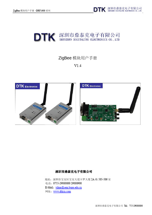
深圳市鼎泰克电子 ZigBee 模块说明书

ZigBee模块用户手册V1.4深圳市鼎泰克电子有限公司地址:深圳市宝安区宝安大道卡罗大厦2A栋505-506室电话:0755-******** 29080900E-Mail:yihua@网址:目录一,ZigBee概述二,DRF系列ZigBee模块的特点三,DRF系列ZigBee模块的参数四,DRF系列ZigBee模块的组网五,DRF系列ZigBee模块的数据传输六,DRF系列ZigBee模块的设置一、ZigBee概述(以下内容引自:百度百科,/view/117166.htm)什么是ZigBeeZigBee是IEEE 802.15.4协议的代名词。
根据这个协议规定的技术是一种短距离、低功耗的无线通信技术。
这一名称来源于蜜蜂的八字舞,由于蜜蜂(bee)是靠飞翔和“嗡嗡”(zig)地抖动翅膀的“舞蹈”来与同伴传递花粉所在方位信息,也就是说蜜蜂依靠这样的方式构成了群体中的通信网络。
其特点是近距离、低复杂度、自组织、低功耗、低数据速率、低成本。
主要适合用于自动控制和远程控制领域,可以嵌入各种设备。
简而言之,ZigBee就是一种便宜的,低功耗的近距离无线组网通讯技术。
ZigBee的起源ZigBee, 在中国被译为"紫蜂",它与蓝牙相类似.是一种新兴的短距离无线技术. 用于传感控制应用(sensor and control).此想法在IEEE 802.15工作组中提出,于是成立了TG4工作组,并制定规范IEEE 802.15.4.2002年,ZigBee Alliance成立.2004年,ZigBee V1.0诞生.它是ZigBee的第一个规范.但由于推出仓促,存在一些错误.2006年,推出ZigBee 2006,比较完善.2007年底,ZigBee PRO推出ZigBee的底层技术基于IEEE 802.15.4.物理层和MAC层直接引用了IEEE 802.15.4在蓝牙技术的使用过程中,人们发现蓝牙技术尽管有许多优点,但仍存在许多缺陷。
ICP DAS ZT-2055 智能zigbee模块用户指南说明书
ZT-2055ZigBee Wireless Module with 8-ch Digital Input and 8-ch Digital Output ModuleQuick Start GuideProduct Website:https:///zt_2055.htmlIntroductionThe ZT-2055 offers 8 isolated channels for digital input and 8 isolated channels for digital output. Either sink-type or source-type digital input can be selected via wire connections. All digital input channels are also able to be used as 16-bit counters. The ZT-2055 supports source-type output with short circuit protection. There are options for configuring power-on and safe digital output values. The ZT-2055 has 16 LED indicators to display the channel status, and has 4 kV ESD protection and 2500 VDC intra-module isolation. Users can easily configure the module address, protocol, checksum, ZB-PID and ZB-channel settings using a combination of rotary and DIP switches.The shipping package contains the following items:ZT‐2055 DIO Device ANT‐124‐05 Quick Start2 Preparing the Device1. Refer the chapter 3. to configure the DIP switch of ZT-2055 I/O device.2. Install the ZT Configuration Utility to configure the ZT-2055 coordinator. CD:\Napdos \ZigBee \ZT_Series \Utility /pub/cd/usbcd/napdos/zigbee/zt_series/utility3. Power Supply: +10 ~ +30 V DC3.1Introduction to the Configuration ParametersA.“Pan ID” parameter is the group identity for a ZigBee network, and must the samefor all devices in the same ZigBee network.“Address/Node ID” parameter is the individed identity of a specific the ZigBeemodule, and must be unique for each device connected the same ZigBee network.B.“RF Channel” parameter indicates the radio frequency channel, and must be set to thesame value as other modules on the same ZigBee network.Channel0x000x01……0x0FFrequency(MHz)24052410 (2480)※RF channels 0x04, 0x09, 0x0E or 0x0F are recommended because they do not overlap with the Wi-Fi frequencies based.802.11b/g802.11b/gChannel 1Channel 62400 000102030405060708090A0B0C0D0E0F 2485MHz MHz802.11b/g Channel (North America)802.15.4 ChannelC. Protocol/Application Mode:When implementing custom programs based on different protocols, the following application modes are recommended in order to ensurecommunicatibleUser Program Protocol DCONModbus RTUModbus TCP ZT-2055 I/O ZT-2550ZT-2570 DCON Transparent TransparentModbus RTUTransparent TransparentModbus Gateway Modbus Gateway Modbus RTU------Modbus Gateway4 Rotation Switch and DIP SwitchThe configuration of ZT-2055 series can be adjusted by using the external rotary switch and the DIP switches. The ZT-2055 device should only be rebooted once the configuration is complete.DIP Switch to the ZT‐2042/ZT‐2043/ZT‐2055/ZT‐2055Protocol Pan ID123456789101112 Address LSB Address MSBChecksum RF Channel Reserved (Node ID)(Node ID)DIP Switch to the ZT‐2055/ZT‐2060Pan IDProtocolAddress LSB Address MSBChecksum RF Channel (Node ID)(Node ID)ZT-2055 - 8-channel DI DAQ module - QuickStart (Dec/2019)ICP DAS USA, Inc. | | 1-310-517-9888 | 24309 Narbonne Ave. Suite 200. Lomita, CA 90717※Once the address of hardware switch is set to 0x00, it mens the address is using software configurations. Refer the more detailed information at Sec. 6.6 of user manual.DIP SwitchNumber Item Status Explain1Address MSB OFF Valid Address (Node ID) from 0x00 to 0x0F ON Valid Address (Node ID) from 0x10 to 0x1F2Protocol OFF DCON ProtocolON Modbus RTUProtocol3Checksum OFF Disabled ON Enabled4ZigBee Pan ID OFF Pan ID = 0x0000 ON Pan ID = 0x00015OFF------ON0x086OFF------ZigBee ON0x04 RF Channel7OFF------ON0x028OFF------ON0x01ZT-2055 - 8-channel DI DAQ module - QuickStart (Dec/2019)ICP DAS USA, Inc. | | 1-310-517-9888 | 24309 Narbonne Ave. Suite 200. Lomita, CA 90717As the ZigBee network is controlled by the ZigBee coordinator, the ZT-2550/ZT-2570 (ZigBee coordinator) must be configured first. Please refert to documents shown below for full details of how to configure these devices.Once configuration of the ZigBee coordinator has been completed. Set the ”Pan ID” and the “RF Channel” values for the ZT-2000 I/O device to the same values as the network, and then reboot the device. The module will automatically start to function on the ZigBee network using the default protocol.※Configuration Utility (Used to configure ZT-2000 I/O device Coordinator)/pub/cd/usbcd/napdos/zigbee/zt_series/utility/ZT-2055 - 8-channel DI DAQ module - QuickStart (Dec/2019)ICP DAS USA, Inc. | | 1-310-517-9888 | 24309 Narbonne Ave. Suite 200. Lomita, CA 90717ZT-2055 - 8-channel DI DAQ module - QuickStart (Dec/2019) ICP DAS USA, Inc. | | 1-310-517-9888 | 24309 Narbonne Ave. Suite 200. Lomita, CA 90717Configurations of ZT‐2550/ZT‐2570Configurations of ZT-2000 I/O DeviceNumber ItemStatus Explain1 Address MSB OFF Address/Node ID is 01(Rotation Switch=1)2 Protocol ON Use Modbus RTU Protocol3 Checksum OFF Disabled4 ZigBee Pan ID OFF Pan ID=0x0000 5ON 0x08 6 ZigBeeON0x04ZigBee RF Channel = 0x0E 7RF ChannelON0x02 8OFF------Once the ZT-2000 I/O device has joined the ZigBee network, the signal quality can be comfirmed by monitoring the status of the ZigBee Net LED indicators. If the LED indicator shows a steady light, communication with the ZT-2000 I/O device has been successfully established for data acquisition and control.ICP DAS also provides the “DCON Utility”, which can be used to simulate DCON/Modbus communication. This software can also be used to verify the device settings and ZigBee I/O functions.※The DCON Utility can be dowmload from:/pub/cd/8000cd/napdos/driver/dcon_utility/Simulate I/O channel operating via using DCON Utilityunch DCON Utility and select the correct COM Port settings to connect theZigBee Coordinator (ZT-2550/ZT-2570).2.Clicking “Search” button will start searching which ZT-2000 I/O device is in thesame ZigBee network.3.If there is any ZT-2000 I/O devices displayed, double clicking the “modulename” will start the I/O channels operated platform.ZT-2055 - 8-channel DI DAQ module - QuickStart (Dec/2019)ICP DAS USA, Inc. | | 1-310-517-9888 | 24309 Narbonne Ave. Suite 200. Lomita, CA 90717ZT-2055 - 8-channel DI DAQ module - QuickStart (Dec/2019)ICP DAS USA, Inc. | | 1-310-517-9888 | 24309 Narbonne Ave. Suite 200. Lomita, CA 907178 Troubleshooting(1)Technical Support.If you have any difficulties using your ZT-2000 series I/O device, please send adescription of the problem to ******************Include the following items in your email:● A description or diagram of the current DIP switch positions.● A copy of the configuration file for the ZT-2000 coordinator. This file can beobtained using the procedure outlined below and should be attached to your email.a.Set the DIP switch of the ZT-255x device to the [ZBSET] position then reboot thedevice. Launch the ZT Configuration Utility and select [Save Log] icon to save the configuration of the ZT-255x as a file.b.After clicking the [Save Log] icon, enter the “File Name” and the “File Path” inthe Windows “Save” dialog box. Once the configuration has been successfullysaved, the following message will be displayed.c.(2)LED Indicator Status:LED Indicator Status IntroductionZigBee Router (Slave)Steady Lit The Signal is StrongBlinking (500 ms)The Signal is AvailableBlinking (1s)The Signal is WeakBlinking (2s)The Signal is Unstable or There is no AvailableThe status of module boardSteady Lit The Power is ON and the Module Initialization is CorrectZigBee PWR Blinking (200ms)Module Initialization Failure(Red LED)Watchdog is Enabled and the status of the I/O channel Blinking (1s)has been changed to the Safe Value. Reset the modulevia the power switch or configuration commands.Steady Unlit The Power is OFFThe status of DI/DO channelsZigBee DI/DO Steady Lit The DI/DO channel is EnabledSteady Unlit The DI/DO channel is Disabled。
zigbee模块设置使用说明
Zigbee简介:Zigbee网络通常由三种节点构成:z协调器(Coordinator):用来创建一个Zigbee网络,并为最初加入网络的节点分配地址,每个Zigbee网络需要且只需要一个Coordinator.z路由器(Router):也称为Zigbee全功能节点,可以转发数据,起到路由的作用,也可以收发数据,当成一个数据节点,还能保持网络,为后加入的节点分配地址.z终端节点(End Device):通常定义为电池供电的低功耗设备,通常只周期性发送数据。
或者通过休眠按键控制节点的休眠或工作。
注意:三种Zigbee节点的P ANID在相同的情况下,可以组网并且互相通讯(上电即组网,不需要人为干预)。
这样可以通过P ANID区分zigbee网络,在同一个区域内,可以同时并存多个zigbee网络,互相不会干扰。
Panid设置见下。
管脚定义:z P1.5:休眠键,输入脚,p1.5拉高时,休眠有效。
模块如果是Cornidator、Router 时此脚无效,只有模块是Enddevice时,此脚才有效,如果不需要休眠功能,则此脚与GND连接。
z p1.7:Set键,输入脚,p1.7拉高时候,设置功能有效,平时模块处于数据收发状态时,此引脚应为低电平,具体设置功能见下节z p2.0 网络连接状态灯,输出脚,模块如果是Router或Enddevice时,此按键表明当前模块是否入网,高电平表明入网,低电平表明没有入网。
z p0.2:Rx,与外置MCU的Tx连接z P0.3:Tx,与外置MCU的Rx连接z GND:电源地z VCC:电源3.3V用户在使用时候,可以根据自己需要选择引脚。
最简单的情况是只使用Rx、Tx.、GND、VCC四个脚,但需要将P1.5(休眠键)、P1.7(设置键)接地。
P2.0(网络连接状态)悬空。
当P1.7为高,通过串口对模块进行设置,数据格式如下(以下数据均为16进制):说明:模块处于设置状态时,波特率固定为38400.即P1.7为高时,模块波特率为38400;P1.7为低时,波特率为设置的波特率,波特率设置见下面命令。
ZigBee模块产品数据手册
ZigBee模块产品数据手册广州星博信息技术有限公司Guangzhou Great Symbol Information Technology Co.,Ltd一、概述ZigBeee模块分为基本型和增强,增强型/基本型模块开放了许多外设端口,两个模块的引脚完全兼容,可以通过SDK对模块进行配置后,使用其相应的外设端口,实现数据的采集、外部设备的控制等,其上面有一个天线接口,用于外接天线。
增强型模块和基本型模块开放的外设端口有:基本型模组(1)1个串行通信接口(UART)(2)4个模拟量输入通道(ADC)(3)14个含复用的通用数字输入输出口(GPIO),不复用ADC/UART时最大为8个(复用:不使用UART/ADC功能时,所有IO可配置成GPIO)●增强型模组(1)42个含复用的通用数字输入输出口(GPIO),不复用ADC /DAC/ UART/ SPI/I2C/ CAN功能引脚时最大为9个(2)3个串行外设接口(SPI),其中1个复用ADC(3)2个内部集成总线接口(I2C),其中1个复用UART(4)1个工业现场总线接口(CAN)(5)4个串行通信接口(UART),其中1个复用I2C(6)12个模拟量输入通道(ADC),其中2个复用DAC,3个复用SPI(7)2个模拟量输出通道(DAC)(8)8个16位同步定时器二、产品特性●基本型模组◆尺寸:PCB贴片封装38.6*23.2*3mm◆重量:约3g◆电源:2V-3.6V 典型值:3.3V◆模块总功耗:A无线模块不工作时平均功耗12-13.5mWB无线模块工作时平均功耗97-121mWC无线模块工作时峰值功耗105-138mW◆天线功率:4dBm◆接收灵敏度:-97dBm◆电流:工作电流小于45mA ,待机电流小于1mA◆工作频率: 2.4G ISM频段◆环境温度:-20~75℃◆无线传输距离:200-250m(外接5dB鞭状天线),300-400m(外接9dB鞭状天线) 注:无线传输的距离测试时环境为:内部增益设定为4dB,空旷的环境下测出的直线距离,中间没有障碍物。
ZigBee模块AT指令操作手册
ZigBee模块AT指令操作手册Version 1.2.7浙江瑞瀛网络科技有限公司版权声明本文档所包含的所有信息均为浙江瑞瀛网络科技有限公司(以下简称“瑞瀛”或“本公司”)版权所有。
未经本公司书面许可,不得向本公司雇员、代理商、合作方或授权许可方以外的任何第三方泄露本文档内容,不得以任何形式擅自复制或传播本文档。
若使用者违反本版权保护的约定,本公司有权追究使用者由此产生的法律责任。
版本更新V1.0.0 2010/06/18 初稿V1.0.1 2010/07/07 增加了AT+UARTRVS=XX,UART反向V1.2.0 2011/06/01 增加了截图说明V1.2.6 2011/09/11 对细节进行了补充说明V1.2.7 2011/12/19 增加AT+SETANT AT+CHOSENCOOAT+MTO指令并对每种类型的模块所支持的AT指令做了明确规定。
目录第一节AT指令简介 (4)第二节AT指令详细使用说明 (6)2.1串口波特率设置 (6)2.2网络标识符设置 (7)2.3模块通信信道设置 (8)2.4设置模块天线选择指令 (9)2.5设置模块无线发射功率指令 (10)2.6设置模块射频发送模式 (11)2.7读取模块配置信息 (12)2.8模块复位命令 (13)2.9读取模块版本号 (14)2.10读取模块地址信息 (15)2.11恢复模块默认设置 (16)2.12设置时间指令 (17)2.13读取时间指令 (18)2.14设置串口帧间隔指令 (19)2.15无线通道能量检测指令 (20)2.16模块休眠指令 (21)2.17模块唤醒指令 (22)2.18获取节点当前网络中COO地址指令 (23)2.19设置节点默认COO地址指令 (24)2.20重新建立网络指令 (25)第一节AT指令简介一般而言通信模块从串口接收命令或数据,如果识别为命令则执行该命令,否则将接收到的数据通过无线的方式发送到指定的目标地址模块。
- 1、下载文档前请自行甄别文档内容的完整性,平台不提供额外的编辑、内容补充、找答案等附加服务。
- 2、"仅部分预览"的文档,不可在线预览部分如存在完整性等问题,可反馈申请退款(可完整预览的文档不适用该条件!)。
- 3、如文档侵犯您的权益,请联系客服反馈,我们会尽快为您处理(人工客服工作时间:9:00-18:30)。
2.4G无线模块WLT2408NZ产品数据手册编号:DSWLT01003 更新日期:2012/04/26 版本:V1.03产品概述WLT2408NZ模块是广州晓网电子出品的WLT系列ZigBee数据传输模块,具备最大8dBm 输出功率,视距传输距离可达500米(@5dbi天线),工作频段2.380GHz~2.500Ghz,除标准ZigBee的16个通道外,还有9个扩展频段,可以有效避开WIFI、蓝牙等其他2.4G信号干扰。
广州晓网电子为WLT2408NZ用户提供mesh对等无线路由协议,无组网延时,采用时间空间权值均衡原则,路由时间短,通讯稳定可靠。
基本参数产品图片输出功率:供电电压:天线接口:数字接口:视距传输距离:功耗:休眠电流工作温度:存储温度:尺寸:-50~+8dBm1.9~3.3VSMA,U.FLUART,GPIO,AD500米@5dbi天线发送峰值电流46.3mA,接收时36.4mA <1uA-40℃至+85℃-40℃至+105℃16×23mm公司简介广州晓网电子科技有限公司是一家专门从事无线通讯方案设计、生产及服务的公司,公司拥有一流的设计团队,运用先进的工作方法,集合无线设计经验,公司拥有业界实用的各种模块,也为客户提供客制化服务。
订货信息WLT2408NZ-S SMA形式天线接头WLT2408NZ-U U.FL形式天线接头WLT2408NZ SDK 无线模块评估板套件,包含两个评估板,搭载的模块为WLT2408NZ-S。
数据手册版权声明本文档提供有关晓网电子产品的信息,并未授予任何知识产权的许可,并未以明示或暗示,或以禁止发言或其它方式授予任何知识产权许可,任何单位和个人未经版权所有者授权不得在任何形式的出版物中摘抄本手册内容。
产品命名规则图1-1 产品命名规则例如:WLT2408NZ-S表示晓网电子模块类的产品,频段为2.4GHz,理论输出功率为﹢8dBm(实际输出为﹢7.7dBm),超小封装,调制方式为ZigBee,外置SMA头的模块。
版本信息目录1. 硬件介绍 (5)1.1实物外观 (5)1.2结构尺寸 (5)1.3性能特点 (6)1.4引脚定义 (7)2. 电气参数 (7)2.1极限电气特性 (9)2.2IO口电平及耐压 (9)2.3RF参数 (9)3. 软件介绍 (10)3.1界面介绍 (10)3.2网络搜索 (11)3.3固件升级 (12)4. 配置实例 (15)4.1配置评估板 (15)4.1数据通讯 (17)5. 设计注意事项 (22)5.1低功耗设计 (22)5.2频段抗干扰设计 (23)6. WLT主机模式通讯协议 (24)6.1命令格式 (24)6.2命令介绍 (24)7. 免责声明 (28)8. 售后服务及技术支持 (29)1. 硬件介绍WLT2408NZ是广州晓网电子科技有限公司推出的2.4GHz无线ZigBee模块,输出功率最大为+8dBm,视距传输距离500米@5dbi天线,模块采用1.9~3.3V供电,支持TTL串口通讯,具备定时器进入休眠及深度休眠功能,休眠电流最低<1μA,尺寸大小为16×23mm。
1.1 实物外观图1-1 WLT2408NZ模块1.2 结构尺寸图1-2 WLT2408NZ结构尺寸【俯视图】图1-3 WLT2408NZ高度【侧视图】SMA头仅在WLT2408NZ-S上使用,因此WLT2408NZ-U高度为9.4mm±0.3mm,WLT2408NZ-S高度为11.2mm±0.3mm。
光盘中有本模块的原理图及PCB封装库文件,AD9格式:原理图封装为“WLT2408NZ.SchLib”,PCB封装为“WLT2408NZ.PcbLib”,PROTEL 99格式:原理图封装为“WLT2408NZ sch.lib”PCB封装为“WLT2408NZ pcb.lib”,以及最小系统电路“WLT2408NZ MinSystem.SchDoc”,用户无需按照本图进行设计。
1.3 性能特点●串口TTL电平,波特率范围1200bps ~ 115200bps;●工作频率为2.380GHz~2.500Ghz,共25个物理频段,可有效的避免自身的频段干扰,也可用扩展频段避开WIFI和蓝牙的干扰;●射频特性:输出功率:+8dBm,接收灵敏度:-98dBm,链路预算:106dBm●两字节PanID,支持65536个网段,不同网段中,可以从软件上区分出网络,互不干扰;●两字节本机地址【目标地址】,同一个物理网段、同一个PanID内,可有65536个ZigBee节点;●发送模式:支持具备应答机制的单播模式和所有节点都收到的广播模式。
●串口参数【波特率、数据位、校验位、停止位】均可配置:●传输速率:250Kbps、500Kbps 和1Mbps 可选;●发送功率,-50dBm ~ +8dBm 可选;●自动重试机制:数据因为外界干扰发送失败时,设备会自动按照设置的重试次数和重试间隔重新发送,如数据量小但重要性非常高,可增加重试次数,保障数据通讯质量;●输入电压:1.9~3.3V;●最大工作电流:46.;●工作温度:-40℃~ +85℃;●保存温度:-40℃~ +105℃;输出功率:+8dBm输出功率为6mW。
接收灵敏度:即保证误码率【10-5 (99.999%) 】下,可接收的最弱信号强度。
链路预算:输出功率-接收灵敏度,这个参数体现了一个无线收发设备的传输能力,传输能力强,要么是可以发出更大的能量,要么是能接收更弱的信号。
1.4 引脚定义图1-4 模块引脚排列图表格 1 模块引脚说明1 AD0 模拟信号采集引脚12位精度,输入电压在1.5V以内2 ISP 短接VCC_3引脚上电进入编程模式3 RESET 复位引脚4 BOOT 进入BOOT模式短接到地,重新上电,设备进入固件升级状态【BOOT模式】5 DEF 恢复出厂配置短接到地,重新上电可恢复所有配置到默认值6 TXD TTL发送引脚7 RXD TTL接收引脚8 PWM3 PWM3输出引脚9 PWM2/CLK PWM2输出引脚/SPI时钟线10 VCC_3 电源输入输入电压范围见2.2节11 GND 电源地12 SPIDO SPI输出引脚13 SPIDI SPI输入引脚14 SLEEP 休眠管脚,低电平脉冲有效2. 电气参数2.1 极限电气特性除非特别说明,下表所列参数是指Tamb=25℃时的值。
2.2 IO口电平及耐压2.3 RF参数3. 软件介绍WltZigBeeCfg 软件是针对晓网电子无线模块的配置软件,可以完成模块的信息获取,配置及远程搜索功能。
图3-1 应用程序图标图3-2 程序界面区域布局3.1 界面介绍3.1.1 串口参数包括串口的波特率、数据位长度、校验位、停止位位数,串口通讯超时时间等参数,必须和设备配置的一致,否则将获取不到信息。
3.1.2 不可更改设备信息显示设备的固件状态,固件版本等。
3.1.3 可更改配置区5.备注栏3.可更改设备参数4.操作台2.不可更改设备信息1.串口参数●设备名:输入15字节数字或英文,用于区别不同的设备,可自定义●设备运行状态测试换行●网络:相同网络号的设备之间才能通讯,此号码从软件上划分网络,格式为两字节十六进制数据,●本机地址:本地的网络地址●目标地址:设置无线通讯的目的地址,与本机地址是配对使用的。
●工作类型:主从模式的选择,详见下一章示例说明●串口波特率:范围从1200bps~115200bps●串口数据位:5、6、7、8●串口校验位:无、奇校验、偶校验、强制为0、强制为1●串口停止位:1、1.5、2●无线速率:250Kbps,500Kbps,1Mbps●发送功率:-50dbm至+8dBm●工作频率:2.380GHz~2.500Ghz ,共25个通道,其中11~26通道为标准ZigBee通道,其他为扩展通道,此设置将物理上划分网络,互不干扰●分帧间隔:串口收到最后一个数据开始计时,超过此时间就将之前的数据打包发走●分帧长度:串口收到此数量的字节后,打包发走●发送重试次数:无线发送失败之后,重新发送多少次才放弃●重试间隔时间:无线发送失败之后,过了设置值的时间后重新发送3.1.4 操作台包括获取信息按钮,修改配置按钮,复位及恢复出厂设置按钮,修改配置需要输入密码,默认为12345,用户可自定义密码。
3.1.5 备注栏解释该选项,并注明注意事项。
3.2 网络搜索使用连接PC的评估板,即可无线搜索网络中的WLT设备。
要进行此操作,请点击“网络设备”选项卡,点击“搜索设备”,在弹出的对话框中,选择要搜索的频段及通信速率,如果已知网络中的设备处于某个通道,可以直接选择该通道搜索,节省搜索时间。
图3-3 搜索网络设备搜索到的设备将显示于设备列表框,点击选中设备,可以按照本地设备操作流程,进行信息获取,配置修改及固件升级操作。
3.3 固件升级如果设备的固件需要升级,请切换到“高级”选项卡,点击“升级”按钮,选中固件文件,点击“升级”即可。
图3-4 点击升级图3-5 选择固件文件图3-6 升级进度4. 配置实例为方便客户评估使用,我们可使用评估板进行测试,评估板硬件如图4-1所示。
图4-1 评估板硬件4.1 配置评估板1.首先安装评估板驱动程序光盘目录“\晓网电子产品光盘\WLT系列产品\驱动及配置软件\USB Driver”下的CP2101_Drivers.exe。
2.安装完毕之后,将评估板通过USB插入电脑。
3.在硬件驱动安装界面,选择驱动所在位置,默认为C:\Cygnal\CP2101\WIN,硬件驱动安装提示会出现两次,第一次安装的是USB驱动,第二次安装的是串口Bridge驱动,二次安装的方法都是一样的,详情请看下面的截图。
图4-2 发现新硬件图4-3 选择驱动所在位置图4-4 不适用Windows Update图4-5 继续安装驱动安装完驱动即可使用评估板了,打开WltZigBeecfg软件,选择评估板专用串口,使用默认的波特率参数,点击“打开串口”,通过简单配置就可以进行数据通讯了。
下一节我们将了解如何选择适合自己应用的通讯模式及配制方法。
4.1 数据通讯数据通讯有两种模式,分别为“点对点透明传输”和“主从模式传输”。
点对点透明传输,顾名思义,指的是通讯只有两点,数据的传输不添加任何协议,A节点串口收到“ABC”,它将通过无线传输到它的目标地址B节点,B节点从串口再输出“ABC”,这类应用特别针对于取代有线串口的场合。
图4-6 点对点通讯模式主从模式传输,指的是网络中有一个主机节点需要对多个从机节点通讯时,主机按照指定的协议,可以将携带从机地址的数据包一次性发给从机,这一点在主机轮询时效率非常高。
