N6说明书-最终版
N6培养基

北京雷根生物技术有限公司
N6培养基
简介:
Leagene N6培养基主要由硝酸钾、氯化钙、硫酸镁、磷酸盐等组成,硝酸钾工作浓度为2830mg/L 、硫酸镁工作浓度为185mg/L 、硫酸铵工作浓度为463mg/L 。
该试剂特点是成分较为简单,其中硝酸钾、硫酸铵含量较高,不含钼,主要用于培养禾谷类花药、细胞、原生质体,经高压灭菌,为无菌溶液。
该试剂仅用于科研领域,不用于临床诊断或治疗。
组成:
操作步骤(仅供参考):
1、 根据实验需求操作。
注意事项:
1、 要根据不同的材料、不同的物种,选择合适的培养基,最好通过实验获得。
2、 如需严格无菌,可再次于121℃高压灭菌15-20min 。
有效期: 6个月有效。
相关:
编号 名称 CM0611 Storage N6培养基 500ml 4℃ 使用说明书 1份
编号 名称 DM0007 瑞氏-姬姆萨复合染色液 PW0040 Western blot 一抗稀释液 TC0699 植物总糖和还原糖检测试剂盒(硝基水杨酸法)。
洛雷科技LH160 ECO 6系列DVR用户手册说明书

WATCH OVER YOUR WORLDFROM ANYWHERE IN THE WORLDDon’t miss a thing with true-to-life video in real-time. LorexStratus Connectivity offers instant connection anywhere yougo with no recurring fees.12/16/242/3TBChannels 960H900TVL ResolutionHDD•Tablet / smartphone viewing and playback 1 •Lorex Stratus Connectivity - 3 step setup•Superior 960H Resolution - 34% more detailed and true-to-life images 2 •Real-time recording at 30fps per channel •24/7 security-grade hard drive•Instant email alerts with snap shot attachment •Continuous, scheduled and motion recording•Advanced mobile apps with live viewing, playback, video recording, and snap shot •PC and Mac compatible•HDMI cable included for simple connection to HD TVs 3 •H.264 video compression 4•Pentaplex operation - view, record, playback, back up & remotely control the system simultaneously •PTZ cameras supported (RS485). Remotely control through App •Accurate time stamps with NTP & Daylight Savings Time •3 video outputs (HDMI, VGA and BNC) to connect multiple monitors•Automatic firmware upgrades over Internet ensure your system is secure and up to date 5DVR FEATURES:130/90FT Night Vision900TVL ResolutionIP66•1.3 Megapixel image sensor (900 TVL resolution)•Lightweight yet extremely durable Polycarbonate housing•Integrated automatic Infrared Cut Filter (ICR) ensures accurate color representation in all lighting conditions •Day/Night mode: Picture automatically switches to B&W delivering better clarity in low light conditions •BrightNight viewing with enhanced low light image sensor•Close-up recognition at night with auto light compensation prevents wash-out effect•Night vision range up to 130ft (40m) in ambient lighting & up to 90ft (28m) away in total darkness 6 •Modern two-tone design - residential and business friendly •Split glass design minimizes IR reflection•Anti-glare feature ensures clear images under strong lighting conditions •3.6mm wide-angle lens captures a wide field of view •Vandal resistant design with cable pass-through bracket •Ideal for outdoor & indoor applications (IP66 Rated) 7•Removable camera base and integrated 3ft camera cable for hassle-free and flexible installation •Versatile mounting options: ceiling, counter or wall mountable •60ft BNC/Power extension cable included per camera•Energy-efficient CEC (California Energy Commission) compliant power adapter includedCAMERA FEATURES:SEE IT ALL -IN GREATER DETAILKeep an eye on your home or business day or night with this high-resolution security camera.130/90FT Night Vision900TVL ResolutionIP66•1/3” Sony Exmor megapixel image sensor (900TVL resolution / 960H) 10 •Lightweight yet extremely durable Polycarbonate housing•Integrated automatic Infrared Cut Filter (ICR) ensures accurate color representation in all lighting conditions •Day/Night mode: Picture automatically switches to B&W delivering better clarity in low light conditions •BrightNight viewing with enhanced low light image sensor•Close-up recognition at night with auto light compensation prevents wash-out effect •Night vision range up to 130ft (40m) / 90ft (28m) 6 •Split glass design minimizes IR reflection•Anti-glare feature ensures clear images under strong lighting conditions •3.6mm wide-angle lens captures a wide field of view (92° diagonal)•ClearNight imaging technology ensures clear night vision and improves recording efficiency up to 30% •3-Axis design for wall / ceiling mounting•Ideal for outdoor & indoor applications (IP66 Rated) 7•Cold climate resistance (-4°ºF / -20°ºC minimum operating temperature)FEATURES:SEE IT ALL - IN GREATER DETAILKeep an eye on your home or business day or night with this high-resolution security camera.•Latest 960H Sony EXview™ II image sensor for excellent low light performance 8•Sony Effio™ video image processor delivers up to 700TV lines of resolution •10X Optical Zoom and 10X Digital Zoom to focus in on even the finest details •Complete area coverage with fast 360 degrees per second panning speed •Program preset viewing points when connected to a DVR•ClearNight technology with Digital Noise Reduction improves low light performance and recording efficiency by up to 30%•Accurate colors with Lorex’s automatic light filtering technology •Easy installation with pre-attached wall mount 9 •Weatherproof (IP66) rated 7•Connects to any Lorex Eco™ or Edge™ series DVR for local or remote operation •100ft all-in-one extension cable included for installation location flexibilityPTZ CAMERA FEATURES:VIEW THE ENTIRE SCENE WITH PAN-TILT-ZOOMDon’t miss a thing with advanced pan-tilt-zoom capabilities and exceptional low-light performance in a compact package.960 H700TVL Resolution10XOptical Zoom360°/SECPanning SpeedSECURITY CAMERA SYSTEMSYSTEMOperating System Linux (embedded)Pentaplex SimultaneousView, Record, Playback, Backup & Remote Monitoring Number of Channels 8/12/16/24chInputs/OutputsVideo IN 8/12/16/24 x 1Vp-p, CVBS, 75ohms, BNCVideo OUT 1 x BNCVGA OUT Y esHDMI Y esAudio IN 8 ch 8 line IN (RCA), G.711, 12/16/24 ch 4 line in(RCA),G.711Audio OUT 1 line OUT (RCA), G.711USB Port 1 at the back, 1 at the frontAlarm IN 8 Alarm INAlarm OUT 1 Alarm OUTVideo Output Resolution 1920x1080 HDMI, 1440x900, 1280x1024, 1024x768PTZ control RS-485 Pelco D & P ProtocolDisplayLive Display 8 ch: 1, 4, 912 ch: 1, 4, 9, 1216 ch: 1, 4, 9, 1624 ch: 1, 4, 9, 16, 24Live Display Speed 8 ch: 240 NTSC, 200 P AL12 ch: 360 NTSC, 300 P AL16 ch: 480 NTSC, 400 P AL24 ch: 720 NTSC, 600 P ALOSD ON/OFFSystem Navigation USB Mouse, IR Remote Controller, Front PanelMotion Area Setting Adjustable grid (30x44) NTSCAdjustable grid (36x44) P ALSensitivity levels 8Firmware Upgrade Automatic over the Internet & via USB device and NetworkUser Authority By user groupTime Synchronization Auto time sync by NTP serverRECORDINGVideo Compression H.264Audio Compression G.711Recording Resolution NTSC:960H:960x480, 960x240, 480x240D1 mode: 720x480(D1), 720x240(2CIF), 360x240(CIF)P AL:960H: 960x576, 960x288, 480x288D1 mode: 720x576(D1), 720x288(2CIF), 360x288(CIF) Recording Resolution Setting Per camera for different resolutionsRecording Quality Control 3 levelsRecording Schedule By hour, by day, by recording mode, by motion, by alarm, by chPre Recording Max.10 SecsPost Recording Max.5 MinutesReliability W atch-Dog, Auto-recovery after power failure Covert Video Y esPLA YBACKPlayback Channel 8 ch: 1~8 Adjustable, 12 ch: 1~12 Adjustable,16/24 ch: 1~16 AdjustablePlayback Speed V ariableMax 16xPlayback Players Backup PlayerSearch By time & eventLog Search Up to 100,000 lines for system, configuration changes,motion/alarm detected, account, record and storage Audio Play Y esSTORAGE & ARCHIVEStorage 8/12/16 ch: Up to 1 HDD’s (SA T A)24 ch: Up to 2 HDD’s (SA T A)Maximum Capacity 8/12/16 ch: up to 1 x 4TB24 ch: up to 2 x 4TBBackup Media USB Flash Drive & HDDBackup File Format H.264 file (A VI generator included) CONNECTIVITYCloud Connection Lorex Stratus ConnectivitySupported Operating Systems Windows™Mac OSRemote Software Client Software (PC) & Safari (Mac)Email notification T extwith snapshotInstant Smart Phone iPad®, iPhone®, Android™& T ablet Support †DDNS Free Lorex DDNSSystem Configuration Full setup configuration over networkPorts Programmable by UserNetwork Protocol TCP/IP / DHCP / UDP / DDNS / PPPoENetwork Interface 10/100-Base-TX, RJ-45Network Speed Control 48Kb ~ 8MB/sec.GENERALPower Consumption Approx. 10 watts (no HDD included)Supply V oltage 8/12/16 ch: 100V AC-240V AC, 12VDC , 2A,50/60Hz24 ch: 100V AC-240V AC, 12VDC , 5A,50/60HzUnit Dimensions 8/12/16 ch: 11.8”/300mm x 9.9”/251mm (W x D x H) x 2.4”/60mm24 ch: 14.9” /380mm x13.3”/340mm x1.9”/50mmUnit W eight (KGs) 8 ch: 1.7 kg/3.75 Lbs12 ch: 1.95 kg/4.3 Lbs16 ch: 2.0 kg/4.43 Lbs24 ch: 3.54 kg/7.8 LbsOperating temperature 32° ~ 104° F / 0° ~ 40° CHumidity10 ~ 90% NCImage Sensor 1/3” 1.3 MP Sony Exmor® CMOS Video Format NTSCEffective Pixels H: 1305 V: 1049Resolution 900 TVL Scan System 2:1 Interlace Sync System I nternal S / N Ratio 48dB (AGC Off)Iris AESAES Shutter Speed 1/60 ~ 1/100,000 sec.Min. Illumination 0.01 Lux without IR LED0 Lux with IR LED Video Output Composite 1.0Vpp @ 75ohm Lens / Lens T ype 3.6mm F2.0 / Fixed FOV (Diagonal) 92°°T ermination BNC T ype IR LED Qty . / T ype 24 pieces / 850nm Night Vision Range 130ft (40m) / 90ft (28m)Power Requirement 12V DC ±10%Power Consumption Max. 320mA (w / IR)Operating T emp. Range –4° ~ 122°F / –20° ~ 50°C Operating Humidity Range < 80% RH Environmental Rating I P66Weight (including stand)0.6lbs / 0.2kg CVC7721PK4BImage Sensor: 1/3” Sony Ex-View HAD CCD II Video Format: NTSCEffective Pixels: 976(H) x 494 (V)Resolution: up to 700 TVLRange: 360° Pan (Endless)160° Tilt (Auto-Flip)Pan/Tilt Speed: Max 360°/Sec.Zoom: 10x Optical Zoom & 10x Digital Zoom Protocol: Pelco-D, Pelco-P Min. Illumination: 0.7 Lux in Color0.02 Lux in Black and White Lens/Lens T ype: Auto Focus / 3.8-38mm F 1.8S/N Ratio: 50db (AGC Off)Iris: Auto Iris Day/Night: IR Cut Filter (ICR)T ermination: BNC Video / RS485 / DC Power Video Output: Composite 1.0Vpp @ 75ohm Power Requirement: 12V DC ±10%Power Consumption: Max. 850mAOperating T emperature Range: -4°F ~ 122°F / -20°C ~ 50°C Operating Humidity Range: within 90%RH Indoor/Outdoor: Both (IP66)Weight:2.9lbs / 1.3kg LZC7092BDimensions:8/12/16 Channel DVRs24 Channel DVR380mm/14.9”300mm/11.8”CVC7721PK4BLZC7092BLDC7722PK4BImage Sensor 1/3” Sony Exmor™ Megapixel CMOS Video Format NTSCEffective Pixels H: 1305 V: 1049Resolution 900 TVL Scan System 2:1 Interlace Sync System I nternal S / N Ratio 48dB (AGC Off)Iris AESAES Shutter Speed 1/60 ~ 1/100,000 Sec.Min. Illumination0.01 Lux without IR LED0 Lux with IR LED Video Output Composite 1.0Vpp @ 75ohm Lens / Lens T ype 3.6mm F2.0 / Fixed FOV (Diagonal) 92°°T ermination BNC T ype IR LED Qty . / T ype 24 IR LEDs / 850nm Night Vision Range 130ft (40m) / 90ft (28m)Power Requirement 12V DC ±10%Power Consumption Max. 320mA (w / IR)Operating T emp. Range –4° ~ 122°F / –20° ~ 50°C Operating Humidity Range < 80% RH Environmental Rating I P66Weight (including stand)0.7lbs / 0.3kgLDC7722PK4BProduct Information:Disclaimers:1. Requires a high speed internet connection and a router (not included). An upload speed of 1Mbps is recommended for the best video performance. Up to 3 devices may connect to the system at the same time. For the latest list of supported apps and devices, check /support.2. Optimized when used with 960H compatible cameras. DVR is backwards compatible and supports different camera inputs: standard resolution and 960H.3. High definition recording not supported, recording resolution is limited to a maximum of 960x480 per channel. Image quality and resolution is dependent on the type of camera connected to the DVR.4. Recording time may vary based on recording resolution & quality, lighting conditions and movement in the scene.5. Both firmware and software must be updated to latest version to ensure remote connectivity. Always update to the latest software (available at ) after upgrading the DVR firmware.6. Stated IR illumination range is based on ideal conditions in typical outdoor night time ambient lighting and in total darkness. Actual range and image clarity depends on installation location, viewing area and light reflection / absorption level of object.7. Not intended for submersion in water. Installation in a sheltered location recommended.8. This camera features an ultra-low light sensitive image sensor and therefore does not feature Infra-Red LEDs. The camera requires ambient lighting (for example, street/building lighting, star or moon light) to render a night time image. In total darkness (zero Lux) the camera will not produce a night time image and therefore the camera should not be installed in completely dark areas.9. Wall mount only. Ceiling mount not supported.10. When connected to a 960H-capable DVR.All trademarks belong to their respective owners. No claim is made to the exclusive right to use the trademarks listed, other than the trademarks owned by Lorex Technology Inc. We reserve the right to change MODEL CONFIGURATION PACKAGE W x D x H Inches & mm WEIGHT CUBE UPC Code LH16162TC12Z1B16 ch ECO6 DVR with 2TB HDD & 12 x 900TVL Cameras (CVC7721PK4B) & 1 x 700TVL PTZ Camera (LZC7092B)Brown Box508mm x 444mm x 513mm 20.0” x 17.5” x 20.2”(estimated)21.8 kg/48.2 lbs (estimated)0.04cbm / 1.62cft6-95529-00115-9LH16243TC129B 24 ch ECO6 DVR with 3TB HDD & 12 x 900TVL Cameras (CVC7721PK4B)Brown Box 508mm x 444mm x 513mm 20.0” x 17.5” x 20.2”(estimated)17.6 kg/38.9 lbs (estimated)0.04cbm / 1.62cft 6-95529-00176-0LH16162TC169B 16 ch ECO6 DVR with 2TB HDD & 16x 900TVL Cameras (CVC7721PK4B)Brown Box 487mm x 393mm x 370mm 19.2” x 15.5” x 14.6”(estimated)13.6 kg/30 lbs (estimated)0.07cbm / 2.51cbf 6-95529-00163-0LH16122TC89B 12 ch ECO6 DVR with 2TB HDD & 8x 900TVL Cameras (CVC7721PK4B)Brown Box 482mm x 304mm x 342mm19” x 12” x 13.5”9.8 kg/21.65 lbs0.011cbm / 0.39cbf 6-95529-00181-4LH16162TC129B 16ch ECO6 DVR with 2TB HDD & 12 x 900TVL Cameras (CVC7721PK4B)Brown Box406mm x 431mm x406mm16” x 17” x 16”13.8 kg/30.6 lbs0.04cbm / 1.62cft 6-95529-00202-6LH16162TC889B 16 ch ECO6 DVR with 2TB HDD & 8x 900TVL Bullet Cameras (CVC7721PK4B), 8x 900TVL Dome Cameras (LDC7722PK4B)Brown Box487mm x 393mm x 370mm 19.2” x 15.5” x 14.6”13.6 kg/30 lbs (estimated)0.07cbm / 2.51cbf 6-95529-00203-3DVR Includes 16 OR 24 Channel DVR with Pre-Installed HDD, HDMI Cable, Remote Control, Power adapter, Mouse, Ethernet Cable, Quick Start Guides Bullet Camera Includes12 x Cameras, 12 x Mounting kit with Allen key, 12 x 60ft BNC / power extension cables, 3 x 4-in-1 Power adaptersPTZ Camera Includes1 x PTZ Camera, 1x 100ft BNC/Power/RS485 Cable, 1 x 13V DC power adapter, 1 x Wall Mount (pre-attached), 1 x Instruction Manual, 1 x Mounting kitDVR Inputs & Outputs。
Litepanels Inca 6 Focusableungsten平衡LED Fresnel说明书
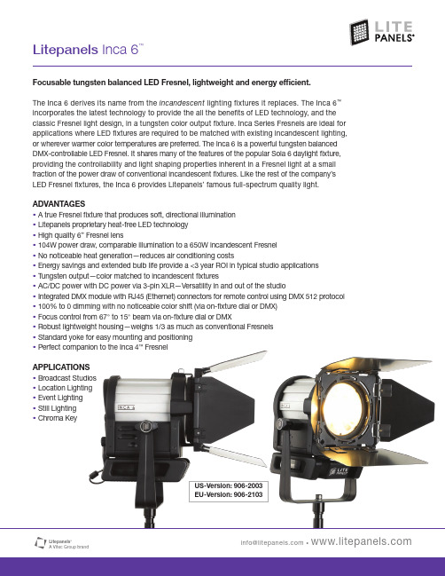
Focusable tungsten balanced LED Fresnel, lightweight and energy efficient.The Inca 6 derives its name from the incandescent lighting fixtures it replaces. The Inca 6™incorporates the latest technology to provide the all the benefits of LED technology, and the classic Fresnel light design, in a tungsten color output fixture. Inca Series Fresnels are ideal for applications where LED fixtures are required to be matched with existing incandescent lighting, or wherever warmer color temperatures are preferred. The Inca 6 is a powerful tungsten balanced DMX-controllable LED Fresnel. It shares many of the features of the popular Sola 6 daylight fixture, providing the controllability and light shaping properties inherent in a Fresnel light at a small fraction of the power draw of conventional incandescent fixtures. Like the rest of the company’s LED Fresnel fixtures, the Inca 6 provides Litepanels’ famous full-spectrum quality light.ADVANTAGES•A true Fresnel fixture that produces soft, directional illumination•Litepanels proprietary heat-free LED technology•High quality 6” Fresnel lens•104W power draw, comparable illumination to a 650W incandescent Fresnel•No noticeable heat generation—reduces air conditioning costs•Energy savings and extended bulb life provide a <3 year ROI in typical studio applications •Tungsten output—color matched to incandescent fixtures•AC/DC power with DC power via 3-pin XLR—Versatility in and out of the studio•Integrated DMX module with RJ45 (Ethernet) connectors for remote control using DMX 512 protocol •100% to 0 dimming with no noticeable color shift (via on-fixture dial or DMX)•Focus control from 67° to 15° beam via on-fixture dial or DMX•Robust lightweight housing—weighs 1/3 as much as conventional Fresnels•Standard yoke for easy mounting and positioning•Perfect companion to the Inca 4™FresnelAPPLICATIONS•Broadcast Studios•Location Lighting•Event Lighting•Still Lighting•Chroma KeyUS-Version: 906-2003EU-Version: 906-2103Specifications subject to change without notice.INCA 6 SPECIFICATIONSSize 11 x 10 x 15" / 28 x 25 x 38cm Weight 9.10 lbs / 4.13kgFresnel Lens 6 inch (15.24cm)Maximum Power Draw 104W Power Requirements 14-28VDC / 100-240VACPower Supply AC/DC 120-240VAC DC power via 3-pin XLR Includes 8-way barn doors, yoke with junior pin adapter, power supplyOPTIONAL ACCESSORIES•5-piece Gel/Filter Set w/Carrying Bag •RJ45 to 5-pin XLR Conversion Cable •Pole Assisted Y okeINCA 6 PHOTOMETRICS DATAl i t e p a n e l s _i n c a _6_b r o a d c a s t _l e d _l i g h t _o n e _s h e e t _i n f o _L e t t e r _ 9.28.12 _m fPrinted in the USA The Litepanels DifferenceFull spectrum quality soft light with visually accurate color temperature The widest variety of LED fixtures and flexible AC or DC power options Smooth dimming from 100% to 0 with no color shiftFlicker-free performance at any frame rate or shutter angle Cool to the Touch ™operation with innovative thermal dynamics Controlled current management for long LED lifeEfficient power management for low power consumption and high reliability Developed and assembled in Los Angeles, CALitepanels was founded in 2001 by 5 professional gaffers and engineers who saw the future and pioneered LED lighting for motion pictures and television. Their Emmy ®award-winning technology has now been used on thousands of productions worldwide. Backed by the Vitec Group’s legacy of 100+ years in the broadcast andproduction industry, Litepanels continues to expand its suite of flicker free, color accurate, soft light that talent and Lighting Directors admire. These environmentally friendly fixtures practically pay for themselves with power savings and long life, setting a new standard in professional lighting.FootcandlesFootcandles。
诺基亚N6智能手机使用说明书上传至百度文库

诺基亚N6智能手机使用说明1 开机拿着手机,手机右边上方有两个键,一个大的,一个小的,按下小的键(即电源/锁定键),长按,等一会儿,屏幕上会出现字,等待,等待,等待,最后会出现时间,就是开机了。
2 解锁开机后,要“解锁”后才能用手机。
屏幕下方有“向上滑动解锁”的文字,遵照说明,用手指按住屏幕,向上滑动一段距离,就“解锁”了。
“解锁”后会出现彩色图标如“电话”等,就可以用了。
3 主要操作手法智能手机只有最下部有一个按键,其余处无按键了。
要操作时,一般是手指点住屏幕,点击,按住向上滑动,按住向下滑动,按住向左滑动,按住向右滑动。
点击,只要用手指点击一下即可。
一般要点击在“图标”的中部,当然,稍微靠边框也是可以的。
不熟练时,点击或按住屏幕时,可以稍用力些按屏幕,不要担心屏幕按坏。
多练习就熟练了。
4 和按键式手机的功能最大不同按键式手机的功能基本是固定的,基本不能增加功能。
智能手机的功能可以被认为是无限多的,除了基本的功能:打电话、看短信外,可以增加许许多多的功能,例如:天气预报、时钟等。
要增加智能手机的功能,需要经过一定的操作,新手暂用现有功能。
5 学习智能手机的使用方法智能手机一般没有使用说明书,主要原因是智能手机的功能无限多,没办法用说明书来细说。
学习智能手机的使用方法,主要有两种方法:1、多用,不要怕按坏。
2、看教学视频。
教学视频也只能讲一部分。
3、左滑,再左滑,至右边第二屏,寻找“360帮帮”图标,点击该图标,女儿可以在武汉指导在监利的爸爸使用手机。
具体请见本文档“360帮帮”。
智能手机中用到的一些专业名词,虽然不太好理解,多问也慢慢会有感觉。
6 智能手机的2个网络智能手机有如下2个网络,有3种使用情况:1、打电话和发短信的网络。
按键式手机就用的这个网络。
一般分为联通网络、移动网络和电信网络。
本机可以使用。
本机2个月后开始计费。
打电话是按分钟计费,发短信是按条计费。
2、互联网的网络。
只有开通互联网的网络,才能用互联网的功能。
A3 EVO 6-axis 陀螺仪说明书
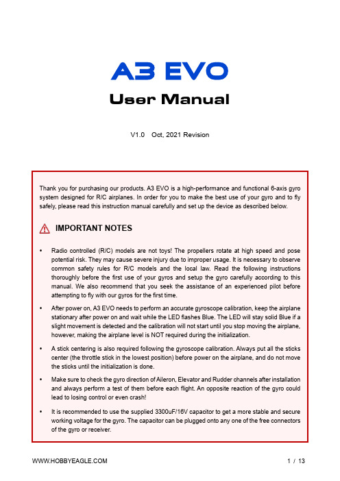
User ManualV1.0 Oct, 2021 RevisionThank you for purchasing our products. A3 EVO is a high-performance and functional 6-axis gyro system designed for R/C airplanes. In order for you to make the best use of your gyro and to fly safely, please read this instruction manual carefully and set up the device as described below.IMPORTANT NOTES•Radio controlled (R/C) models are not toys! The propellers rotate at high speed and pose potential risk. They may cause severe injury due to improper usage. It is necessary to observe common safety rules for R/C models and the local law. Read the following instructions thoroughly before the first use of your gyros and setup the gyro carefully according to this manual. We also recommend that you seek the assistance of an experienced pilot before attempting to fly with our gyros for the first time.•After power on, A3 EVO needs to perform an accurate gyroscope calibration, keep the airplane stationary after power on and wait while the LED flashes Blue. The LED will stay solid Blue if a slight movement is detected and the calibration will not start until you stop moving the airplane, however, making the airplane level is NOT required during the initialization.• A stick centering is also required following the gyroscope calibration. Always put all the sticks center (the throttle stick in the lowest position) before power on the airplane, and do not move the sticks until the initialization is done.•Make sure to check the gyro direction of Aileron, Elevator and Rudder channels after installation and always perform a test of them before each flight. An opposite reaction of the gyro could lead to losing control or even crash!•It is recommended to use the supplied 3300uF/16V capacitor to get a more stable and secure working voltage for the gyro. The capacitor can be plugged onto any one of the free connectors of the gyro or receiver.Use one of the supplied double-sided tape to attach the gyro to your airplane firmly. For best performance, the gyro should be mounted as close to the C.G. as possible, and the housing edges must be aligned exactly parallel to all three rotation axes of the plane. The gyro can be attached flat or upright, and even upside down, however, you have to ensure that the shorter side with the setting button always points toward the heading direction of the airplane, otherwise the gyro will not work normally in LEVEL and HOVER modes.①Flat, face up ②Flat, face down③Upright, button up ④Upright Inverted, button downNOTES•Never use the hot-melt glue or nylon ties to fix the gyro onto the airplane!•You need only one piece of the tapes each time, a soft or thick mounting may probably impact the performance of the gyro.•The gyro is a sensing device, please make enough space around it and keep as far away from other electronic devices or wires as possible.NOTES•[MODE] is used for flight mode switching of the gyro, connect it to a 3-way switch channel of the receiver to switch the flight mode in flight.•[SBUS/PPM/G] is used for remote master gain adjusting, connect it to a proportional channel of a volume or slide lever of the transmitter to tune the master gain in flight.•The ESC or throttle servo is connected to the throttle channel of the receiver directly without passing through the gyro.•Pay attention to the polarity of the plugs. The orange signal line must always be on the top and the brown on the bottom.St andard PWM Receiver ConnectionSingle-line Receiver ConnectionA3 EVO supports PPM and Futaba S.Bus serial receivers which allows you to connect the gyro to the receiver with one single wire. When using a specific type of these receivers the appropriate type of receiver channel allocation will be preset in the A3 EVO. Please refer to the table below and check if yourradio transmits the channels in the correct order. If you use a standard PWM receiver with standard wiring layout the channel mapping does not apply. When A3 EVO is operating in single line receiver mode, the [THR Out/AIL] can be used as the throttle output channel for the ESC or the throttle servo if a mini receiver is being used which has no additional output connectors.Please note that the Remote Master Gain is disabled in single line mode as default. Choosea channel number for gain channel in item 11 of the Setup Menu to activate this feature if needed.Table 1: Default Channel Mapping for Single Line ReceiversAIL ELE THRPPM Receiver CH1CH2CH3CH4CH5-Futaba S.Bus (FrSky SBUS or WFLY WBUS)CH1CH2CH3CH4CH5-A3 EVO provides 4 flight modes which can be switched by a 3-position switch of the transmitter during flight. We have provided you with 4 different mode allocation corresponding to the 3 positions of the switch in Item 7 of the Setting Menu, the default setting is MODE 1: NORMAL – LEVEL - HOVER. The color of the LED shows the current flight mode of the gyro while in use.Table 2: Colors of the LED for Flight ModesTable 3: Flight Mode Allocations1. GYRO OFF ModeWhen operating in GYRO OFF mode the gyro will be deactivated completely, and the airplane will be completely under the control of your transmitter as it was before installing the gyro. This mode is usually used for testing purpose only.2. NORMAL ModeThe NORMAL mode, also known as the ‘Rate mode’, is the most basic function of the gyro. It works based on the rotation rate control of each axis of the airplane. When operating in this mode, the gyro will only correct currently occurring rotational movements, a momentary reaction will be applied to the servos when the airplane rotating on corresponding axis, after rotation the servos will move back to their neutral position as soon as the airplane standing still immediately. The NORMAL mode can be used with nearly any size and type of airplanes. It can effectively improve the stability and precision of the airplane and reduce the stall point specially.3. LEVEL ModeThe LEVEL mode is also known as the ‘Auto-Level mode’, ‘Auto-Balance mode’ or ‘Horizon mode’. When operating in this mode, the airplane will be brought to horizontal position automatically when releasing the sticks. Different from the ANGLE mode, there is no maximum angle limitation in this mode and the airplane will be stabilized only when there is no specific control input from aileron and elevator sticks. This mode can be used if the pilot becomes disoriented and would like to save the airplane from crashing.4. HOVER ModeThe HOVER mode, also known as the ‘Auto-Hover mode’, provides the same functionality as the LEVELmode. The only difference is that when you release the sticks, the airplane will be brought to vertical position (nose up) and keeps hovering. This mode is designed to help you to learn hovering maneuver and reduce the probability of crashing.Basic GainThere are 3 trimming potentiometers on the front of the A3 EVO. They are used to adjust the basic gain of the gyro for Aileron, Elevator and Rudder separately. Clockwise for increase, anticlockwise for decrease. Basic gain determines the momentary reaction strength of the gyro. In general, the higher the gain the harder the airplane will stop after rotation and the more stable and precise the airplane will fly. But if the gain is too high the airplane will tend to oscillate at high frequency on the corresponding axis. If too small, the operation and stability will not be so good and the airplane does not stop precisely and overshoots. The gyro will be deactivated completely if you turn the basic gain to 0%.For the first flight test it is recommended to start with a lower basic gain setting (e.g. 30%) and switch the gyro to NORMAL mode. In case the airplane starts to oscillate in flight then reduce the gain of the corresponding axis. If the control feels weak and imprecise and does not hold position when stopping then increase the gain, according to this approach, fine tune the basic gain until you get the best performance.Remote Master GainThe [SBUS/PPM/G] is used to control the remote master gain for parallel PWM receiver. You can make a linear adjustment by using a volume or slide lever on your transmitter or make a 3-level gain selection using a 3-position switch. This function is optional, the master gain will always default to 100% if you do not connect it. Master gain will not affect the basic gain setting on the gyro.Setup MenuTo get into the Setup Menu, press and hold the button for about 2 seconds until the LED starts flashing Blue and Red quickly. The Setup Menu contains 11 setting functions which normally only need to be setup once after installation.Function SelectionIn the Setup Menu, the LED will flash Blue and Red several times every 3 seconds in a loop and the number of times LED flashes shows at which function item you are currently. For example, one Blue and Red flashing means the first setting “Aileron Gyro Direction”, after waiting about 3 seconds, a twice Blue and Red flashing means the second setting “Elevator Gyro Direction”, and so on.Option SwitchingWhen you reach the function that you wish to operate in, short press the button to get into it. After entering in, the current selected option is indicated by the color of the LED. Each short press of the button advances the option to the next value. After you finish making your selection, just wait for 5 seconds until the LED starts blink quickly which indicates that the modified is saved and then you will be brought back to the Setup Menu level automatically. If you do not want to change anything, just wait for timeout without any operation.Exit of MenuTo exit the menu just keep the button pressed for 2 seconds again until the LED starts flashing Blue and Red quickly.Blue&Red Flash ing 1-3. Gyro DirectionThe top 3 items of the Setting Menu is used to reverse the gyrodirection for Aileron , Elevator and Rudder . The color of LEDshows you the gyro direction currently selected, the default setting is Normal (Solid Blue). Each short press of the buttonwill switch between Normal and Reversed . After you finishmaking your selection, just wait for 5 seconds until LED starts blink quickly which indicates that the modified is saved and then you will be brought back to the Setup Menu level automatically.VERY IMPORTANT!It is extremely important to make sure that the gyro reacts in the correct direction for each channel before flight. An opposite reaction of the gyro could lead to losing control or even crash!Check the gyro direction for Aileron Quickly move the right wing downward around the roll axis, the right aileron surface should flap down and the left flap up as shown below.Check the gyro direction for Elevator Quickly move the nose of the airplane downward around the pitch axis, the elevator surface should flap up as shown below.Check the gyro direction for Rudder Quickly move the nose of the airplane to the left around the yaw axis, the rudder surface should flap right as shown below.4. Wing TypeThe 4th item of the Setup Menu is used to setup the wingtype. A3 EVO supports standard fixed-wing, flying-wing(delta-wing) and V-tail. The color of LED shows you the wing type currently selected. The default setting is Standard(Solid Blue), each short press of the button will switch to thenext type. After you finish making your selection, just wait for 5 seconds until LED starts blink quickly which indicatesthat the modified is saved and then you will be brought back to the Setup Menu level automatically.NOTES• Make sure that there are no mixing functions active on your transmitter. Have a look at the radio’s servo monitor and verify that each stick controls only one output channel. • If two aileron servos are being used, please connect a Y-extended lead to [OUT1]. •Most flying-wings have no rudder, in this case, [RUD] is unnecessary to connect.Servo Connection Illustration5. Receiver TypeThe 5th item of the Setup Menu is used to choose the receiver type. The color of LED shows you the receiver type currently selected. The default setting is PWM Receiver (Solid Blue), each short press of the button will switch to the next value. After you finish making your selection, just wait for 5 seconds until the LED starts blink quickly whichindicates that the modified is saved and then you will be brought back to the Setup Menu level automatically.Restart the gyro to make the new receiver type setting take effect!6. Mount Orient ationThe 6th item of the Setup Menu is used to setup themounting orientation of the gyro. The color of LED showsyou the orientation currently selected. The default setting isFlat, face up (Solid Blue), each short press of the button willswitch to the next value. After you finish making yourselection, just wait for 5 seconds until LED starts blinkquickly which indicates that the modified is saved and thenyou will be brought back to the Setup Menu levelautomatically.The setting here should be the same as the mounting orientation of your unit installed in the airplane, otherwise the gyro will not work normally.7. Flight Mode AllocationThe 7th item of the Setup Menu is used to select the flightmode allocation definition for the 3-position switch. Thecolor of LED shows you the orientation currently selected.The default setting is Mode-1 (Solid Blue), each short pressof the button will switch to the next value. After you finishmaking your selection, just wait for 5 seconds until LEDstarts blink quickly which indicates that the modified issaved and then you will be brought back to the Setup Menulevel automatically.See “Table 3: Flight Mode Allocations” on page 5 for description of each mode.8. Servo FrequencyThe 8th Item of the Setup Menu is used to select the working frequency of the servos. The color of LED shows you the frequency currently selected. The default setting is 50Hz (Solid Blue), each short press of the button will switch to the next value. After you finish making your selection, just wait for 5 seconds until LED starts blink quickly which indicates that the modified is saved and then you will be brought back to the Setup Menu level automatically.Please note that the analog servos can only work with 50Hz. If you do not know what the maximum update rate that is tolerated by your servos never use more that 50Hz. The higher the frequency the better it is for the flight performance of the gyro but you must check the servo specifications before increasing the setting. Otherwise, the servos may get damaged!9. Level CalibrationWhen flying in LEVEL mode, A3 EVO needs to know the angle of the airplane in both roll and pitch directions, this is achieved by calculating the attitude of its own. A small angle deviation caused by installation can lead to an unexpected behavior when flying in LEVEL mode. For this reason, a level calibration is recommended to offset the error caused by installation and to establish a proper level reference of your airplane after installing the gyro.Before calibrating, the airplane should be placed on the horizontal ground and make the wing parallel to the ground. Make the airplane slightly nose-up because a certain elevation angle is usually required to maintain level flight for most airplanes. Short press the button when you reach the 9th item of the Setup Menu, then LED will start blink Blue rapidly for several seconds, do not move the airplane and keep its attitude until the calibration is done.10. Hover CalibrationAs a same reason, a hover calibration is recommended to perform after installation if you want to fly with HOVER mode. The procedure is quite similar to that of level calibration. The only difference is that before calibrating, you need to lift the airplane and make it vertical to the ground instead of putting it on the ground.Short press the button when you reach the 10th item of the Setup Menu, then LED will start blink Blue rapidly for several seconds, do not move the airplane and keep its attitude until the calibration is done.11. Remote Master Gainthe remote master gain function for SBUS or PPM receivermode. The master gain is disabled as default when leavingthe factory, you need to choose either channel 6 or channel7 as the gain channel to activate this feature if needed.* F actory ResetTo restore the gyro to factory default settings, press and hold the button while turn on the power of the gyro, release it when LED starts flash Blue and Red. (FYA: the button needs to be hold for more than 4 seconds), after successfully entering the program the LED will remain flashing Blue, press and hold thebutton again for about 2 seconds until the LED starts flash Blue quickly, release the button to confirm thereset. After a successful reset the gyro will start the initialization automatically.* Accelerometer CalibrationBefore leaving the factory, every unit has been carefully tested and calibrated. Usually, you do not need to perform a calibration of the accelerometer during use. However, in some specific cases, we would suggest you re-calibrate the accelerometer to obtain better performance, these include temperature changes those will probably cause the mechanical characteristics changes of the sensor, or replacement of new sensor, etc. The calibration should be done on a horizontal desktop and the gyro needs to be removed from the airplane.Entering the Calibration ProgramTo access the accelerometer calibration program, press and hold the button while turn on the power of the gyro, release it when LED turns Blue and Red.Calibration StepsA3 EVO uses a quick approach for accelerometer calibration, there are only 2steps corresponding to both sides of Z axis of the unit required to becalibrated. Each step will take about 2 seconds. While calibrating, the LED willflash Blue several seconds and then light up solid in Blue. Do not move thegyro until the calibration is done.①Put the gyro flat and face up on the table and make it parallel to thedesktop. short press the button, do not move the gyro while the LED isflashing Blue quickly.②Put the gyro flat and face down on the table and make it parallel to thedesktop, short press the button, do not move the gyro while the LED isflashing Blue quickly.③After you have finished the 2 steps above, the LED will flash Blue andRed once which indicates that the calibration is complete, after a successfulcalibration the gyro will start the initialization automatically.Blue, Flashing Power-on initialization and self-test Solid Blue NORMAL ModeSolid Red LEVEL ModeSolid Blue&Red HOVER ModeLED Off GYRO OFF ModeRed, Slow Flashing No receiver signal detected Blue, Fast Flashing Calibrating or testingRed, Fast Flashing Gyroscope sensor error。
四工位专用机床课程设计说明书超详细
设计任务书设计任务:1 按工艺动作过程拟定机构运动循环图2 进行回转台间歇机构,主轴箱道具移动机构的选型,并进行机械运动方案评价和选择3 按选定的电动机和执行机构的运动参数进行机械传动方案的拟定4 对传动机构和执行机构进行运动尺寸设计5 在2号图纸上画出最终方案的机构运动简图6 编写设计计算说明书设计要求:1 从刀具顶端离开工件表面65mm位置,快速移动送进了60mm后,在匀速送进60mm (5mm刀具切入量,45mm工件孔深,10mm刀具切出量),然后快速返回。
回程和工作行程的速比系数K=2。
2 生产率约每小时60件。
3 刀具匀速进给速度2mm/s,工件装、卸时间不超过10s。
4 执行机构能装入机体内。
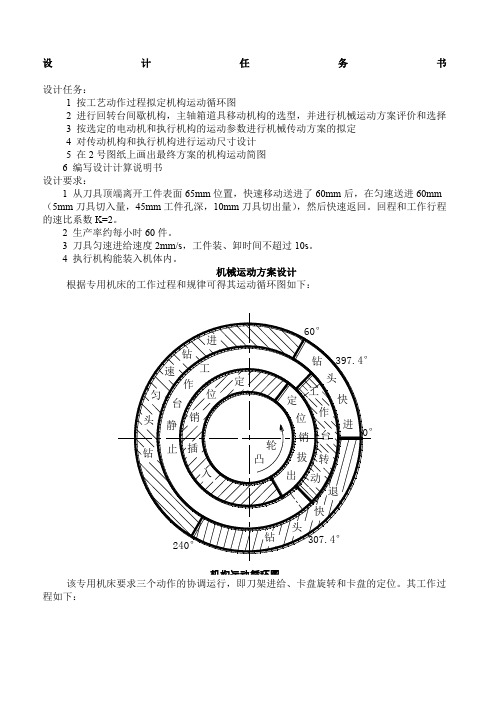
机械运动方案设计根据专用机床的工作过程和规律可得其运动循环图如下:机构运动循环图该专用机床要求三个动作的协调运行,即刀架进给、卡盘旋转和卡盘的定位。
其工作过程如下:要确保在刀具与工件接触时卡盘固定不动,刀具退出工件到下次接触工件前完成卡盘旋转动作。
几个动作必须协调一致,并按照一定规律运动。
机械总体结构设计一、原动机构:原动机选择Y132S-4异步电动机,电动机额定功率P=5.5KW,满载转速n=1440r/min 。
二、传动机构:传动系统的总传动比为i=n/n 6,其中n 6为圆柱凸轮所在轴的转速,即总传动比为1440/1。
采用涡轮蜗杆减速机构(或外啮合行星减速轮系)减速。
三、执行部分总体部局:执行机构主要有旋转工件卡盘和带钻头的移动刀架两部分,两个运动在工作过程中要保持相当精度的协调。
因此,在执行机构的设计过程中分为,进刀机构设计、卡盘旋转机构和减速机构设计。
而进刀机构设计归结到底主要是圆柱凸轮廓线的设计,卡盘的设计主要是间歇机构的选择。
在执行过程中由于要满足相应的运动速度,因此首先应该对于原动机的输出进行减速。
下面先讨论减速机构传动比的确定:由于从刀具顶端离开工件表面65mm 位置,快速移动送进了60mm 后,在匀速送进60mm (5mm 刀具切入量,45mm 工件孔深,10mm刀具切出量),然后快速返回。
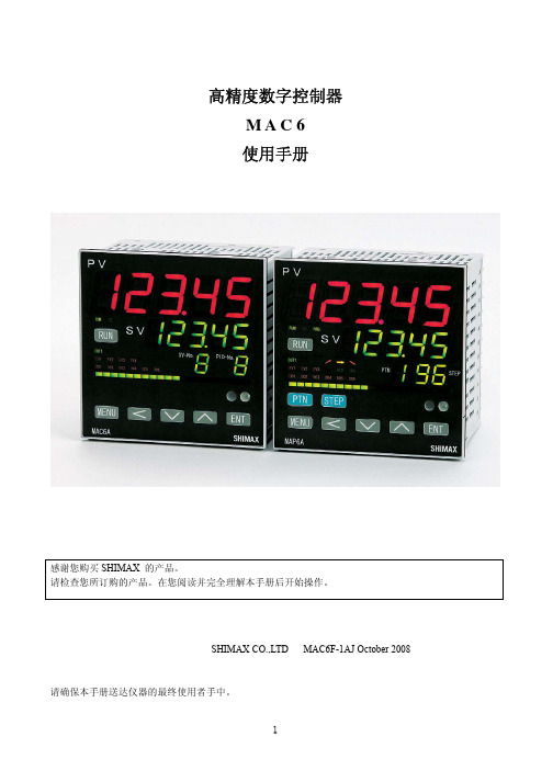
MAC6中文说明书
3-3 订货信息
项目 型号 输入
代码 MAC6A-
调节输出 1
电源
规格 96×96mm 5 位数字显示高精度字控制器 M 自由输入、TC、RTD、mV、V、mA
C 继电器接点 1a 240V AC 2A( 阻性负载 ) S 固态继电器(SSR)驱动 12V DC 最大20mA I 电流 4-20mA DC 负载电阻最大500Ω V 电压 0-10V DC 负载电流最大2mA Y 控制电机 (伺服控制输出)接点容量1C 240V AC 2A X 控制电机 (伺服控制输出)SSR 240V AC 2A
3
生电磁干扰。请在采取有效措施后使用。 ● 仪器具有用于散热的通风口,并且确保金属不会进入通风口中,否则会引起故障或者火灾。 ● 不要阻塞通风口或者使尘埃和其他类似物附着在上面,温度升高或者绝缘失效都会缩短产品寿命并
引起火灾。 ● 应该注意在重复性极限值(如电压、噪声、浪涌)实验时可能会损坏设备。 ● 禁止使用者改型和不正当使用。 3 简介 3-1 使用前的检查
在使用 MAC6 前请检查型号代码、外观和附件。确认没有错误、损坏和丢失。 确认型号代码,检查与订货的产品一致。根据下述代码表检查机壳上的型号代码。 检查附件 「注」 如果您有任何问题请联系我们的代理商或者营业本部。我们欢迎任何询问,例如,产品缺
陷、附件丢失等。
「 注意 」
3-2 使用注意事项 ●不要用硬的、尖的物体操作前面板。不要用指甲尖触碰按键。 ●当清洁仪器时,用干布轻擦。不要使用溶剂,如,稀释剂。
7. 功能的补充说明・・・・・・・・・・・・・・・・・・・・・・・・・・・・・・・・・・・・・・・・・・・・・・・・・・・・・・・・・・・・・・・60
7-1 自动返回功能・・・・・・・・・・・・・・・・・・・・・・・・・・・・・・・・・・・・・・・・・・・・・・・・・・・・・・・・・・・・・60 7-2 输出软启动功能・・・・・・・・・・・・・・・・・・・・・・・・・・・・・・・・・・・・・・・・・・・・・・・・・・・・・・・・・・・60 7-3 事件报警方式・・・・・・・・・・・・・・・・・・・・・・・・・・・・・・・・・・・・・・・・・・・・・・・・・・・・・・・・・・・・・60 7-4 AT(自整定)・・・・・・・・・・・・・・・・・・・・・・・・・・・・・・・・・・・・・・・・・・・・・・・・・・・・・・・・・・・・・60
B6,B6AC中文说明书
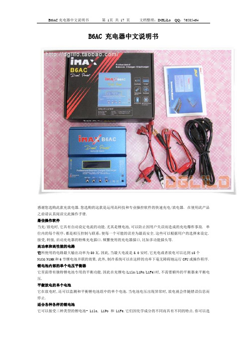
B6AC 充电器中文说明书感谢您选购此款充放电器.您选购的这款是运用高科技和专业操控软件的快速充电/放电器. 在使用此产品之前请认真阅读完此操作手册.最佳操作软件当充/放电时,它具有自动设定电流的功能.尤其是锂电池,可以防止因用户失误而造成的充电爆炸事故. 单位内的每个程序,都是相互控制与联系,使每一个可能的误差为最高安全.这些可以根据用户的选择来设定.接受,转接,启动充电器的特殊充电插口.频繁使用的充电器插口,比如多功能插头等.高功率和高性能的电路它所使用的电路最大输出功率为50瓦.因此,当最大电流是5.0安时,它充电或者放电可以达到15个NiCd/NiMH和6节锂电池并联的效果.此外,制冷系统可以在这样的功率下毫无障碍地运行CPU或操作程序. 锂电池内部的单个电压平衡器它里面带有独特锂电池专用的平衡功能.因此在充锂电(Lilo/LiPo/LiFe)时,不需要额外的平衡器来平衡电压.平衡放电的单个电池它在放电时,还可以监测和平衡锂电池组中的单个电池.当电池电压出现异常时,放电就会伴随错误信息而停止.适合各种各样的锂电池它可以接受三种类型的锂电池- Lilo, LiPo 和 LiFe.它们因化学成分的不同而具有不同的特点.你可以选择他们中任一一种来使用,根据它们的规格,参照”警告和安全说明书”.锂电池快速和存储模式你可以充电锂电池作特殊用途。
快速充电减少了锂电池的充电时间,而存储模式也使得锂电池的额定电压可以长时间的储存.最大化安全Delta-peak sensitivity:一种自动充电电流关闭程序,其工作原理是在电池电压上升至最高点而开始回降时,将充电电流关闭完成充电.(镍镉/镍氢)自动充电电流限制:在自动电流模式下充镍镉或镍氢电池,你可以设置充电电流的上限以避免高充电电流.在’AUTO’模式下,在充低阻碍,小容量的镍氢电池时非常有用.容量限制:充电容量以充电电流×充电时间来计算.在设定了最高充电值的情况下,当充电容量超过了最高限额时,程序将强制结束充电.温度限制:充电时,电池由于内部发生化学反应,温度也将相应增高.如果对充电器设定温度限制,在温度到达最高限额时,程序将强制结束充电.充电时间限制:对充电时间进行限制也可以防止任何可能的错误.输入电流检测器:为保护蓄电池在电流输入时不受损坏,通常可以对其电压进行检测.当电压下降至最低额时,程序将自动关闭充电电流.自动制冷风扇:只有在单个电池的内部温度升高时,电子制冷风扇才自动运转.资料存储/下载为方便用户,它最多可以存储5个数据不同的电池.你可以建立包含了程序设置的数据来持续不断的充电或是放电.在你需要的任意时候都可以叫出这些数据,并且这个过程在没有设定程序时执行.循环充电或者放电持续不断的运转1-5周期使电池得以更新和平衡.充电器外观警告和安全提示○任何情况都不要在无人看管的情况下充电.如果有故障出现,请立即结束程序,再查阅程序说明书.○不要放在有灰尘,潮湿,太阳直射或振动的地方,不要摔它.○进入电源只允许10-18DC电源.○充电器和电池在充电或放电时应放置在强抵抗,防易燃和抗导体的表面上.切勿放在汽车坐垫上,地毯上或类似物体上.确保所有易然易爆物品远离操纵区域.○充电器的冷却口不能被覆盖或关闭,以便提供良好的通风.确保准确地掌握要充电和放电的电池性能.如果程序设置错误可能损坏电池.尤其是锂电池,可能会导致火灾或充电过度导致爆炸.NiCd/NiMH 电压等级: 1.2v/cell允许快速充电电流: 1C~2C依赖于电池的运转.放电电压切断级别:0.85v /cell(镍镉电池), 1.0v/cell (镍氢电池)Lilo 电压等级:3.6V/c最大充电电压: 4.1V/cell允许快速充电电流: 1C或更少最小放电电压切断级别:2.5V/cell或更高○为避免充电导线之间发生短路,应先将充电导线与充电器连接, 然后再连接电池,拆开线路时,步骤相反. -你必须注意核实锂电池组的容量和电压.它可能是串,并联混合组成.并联时,电池组的容量是每个电池的容量乘以电池的个数,而电池组的电压不变. 在充电过程中,这种电压不平衡引起火灾或爆炸,我们建议你串联锂电池组.○放电放电的典型目的是确定电池剩余的容量或是降低电池的电压来界定级别.当你给电池放电时,必须和充电时一样注意放电过程.为了避免电池放电过度,一定要正确设定额定放电电压.锂电池不能低于最低电压,因为这样会导致容量的快速损失或者完全失败.一般来说,不需要给锂电池放电.-据说一些充电电池有记忆效应。
- 1、下载文档前请自行甄别文档内容的完整性,平台不提供额外的编辑、内容补充、找答案等附加服务。
- 2、"仅部分预览"的文档,不可在线预览部分如存在完整性等问题,可反馈申请退款(可完整预览的文档不适用该条件!)。
- 3、如文档侵犯您的权益,请联系客服反馈,我们会尽快为您处理(人工客服工作时间:9:00-18:30)。
广域网配置
自 动 从 你 的I S P供 应 商 获 取 一 个I P地 址 静 态I P 请 填 写 网 络 供 应 商 提 供 给 您 的I P地 址
若 网 络 供 应 商 提 供 给 您 账 号 密 码 请 使 用P P P O E 广 域 网I P 子网掩码 广域网网关 备 用D N S
扫描AP
TOTOLINK N6
扫描AP
无线网络配置 高级
用Windows配置我的无线网络配置 可用网络(N) 要连接断开区域内无线网络或查找有关更多信息,请单 击下面的按钮。
查看无线网络
首选网络(P) 按下面的顺序自动连接到一个可用网络:
TOTOLINK_
上移(U) 下移(D)
添加(A) 删除(R) 了解无线网络设置配置
* R S T / W P S按 键 为T O T O L I N K N 6的 复 位 键 。 在 通 电 的 状 态 下 按 住R S T / W P S 键5秒 到1 0秒 左 右 后 松 开 , 断 电 后 重 新 连 接 , 路 由 器 即 恢 复 出 厂 值 。
* 模式选择开关用于选择TOTOLINK N6的工作模式,有Router模式和AP模式 两种。
USB插座
插座
USB连接线 N6
TOTOLINK N6
平板 电脑
电话
TOTOLINK N6
上网方式 静 态I P
动 态I P
开通网络时,网络运营商提供的上网参数 固 定 的I P地 址 、 子 网 掩 码 、 网 关 、D N S服 务 器 用户名和密码
宽带服务商没有提供任何参数,不用路由器时 可直接上网,计算机不需要做任何设置。
5 11 11 选择AP
TOTOLINK N6
无线设置
无线功能 模式 无 线 网 络 名 称(SSID) S S I D广 播 区域 频宽 认证类型 加密 加密密钥
启用
禁用
启用 禁用 中国 20 20/40 加密 关闭 WEP64 12345678
WEP128
TKIP AES 应用
TOTOLINK N6
广域网配置
自 动 从 你 的I S P供 应 商 获 取 一 个I P地 址 静 态I P 请 填 写 网 络 供 应 商 提 供 给 您 的I P地 址
若 网 络 供 应 商 提 供 给 您 账 号 密 码 请 使 用P P P O E
TOTOLINK N6Fra bibliotekUSB插座
插座
USB连接线 N6
平板 电脑
警示:
1、 雷 雨 天 气 晴 将 设 备 及 所 有 连 接 线 拆 除 ; 2、 远 离 热 源 , 保 持 通 风 3、 在 存 储 、 运 输 和 运 行 环 境 中 , 请 注 意 防 水 ;
进入路由配置界面
TOTOLINK N6
TOTOLINK N6 N6
TOTOLINK
接L A N口 网线
广域网配置
自 动 从 你 的I S P供 应 商 获 取 一 个I P地 址 静 态I P 请 填 写 网 络 供 应 商 提 供 给 您 的I P地 址
若 网 络 供 应 商 提 供 给 您 账 号 密 码 请 使 用P P P O E 用户名 密码
A : T O T O L I N K N 6做A P使 用
TOTOLINK N6 TOTOLINK N6
有 线 网 络 接 口( L A N )
网线 USB插座
插座
USB连接线 N6
平板 电脑
电话
TOTOLINK N6
USB插座
插座
USB连接线 N6
平板 电脑
电话
USB插座
插座
USB连接线 N6
平板 电脑
电话
TOTOLINK N6
TOTOLINK N6
重新扫描 信道
属性(O)
高级(V)
N6说明书
2.0USB连接线 查看可用的网线连接
N6
正面
背面
侧面
硬件连接: 将U S B连 接 线 一 头 接N 6, 一 头 接 入 适 配 器 的U S B接 口 , 如 下 图 所 示 :
USB插座
插座
USB连接线
N6
* T O T O L I N K N 6电 源/ C P U灯 闪 烁 , 表 示 系 统 正 常 ; 若 指 示 灯 不 亮 则 为 不 正 常 , 请检查连接是否正确。