UNIGAS说明书-中文版
MONOGRAM真空集便器说明书说明书

附录 MONOGRAM 真空集便器说明书
3、零部件描述 A、液位开关(见图 6,19 项) 液位指示开关是装在污物箱内的浮球。一个开关是指示液位达到 80%箱满状
态的,另一个指示 100%箱满状态的。通过系统控制器检测的存污状态,相应的 指示灯会亮。
B、冲洗喷嘴装配(见图 6,22 项) 污物箱的顶端装有两个冲洗喷嘴及相关配件。在排放污物时,从冲洗喷嘴里 喷出水来冲刷污物箱的内面。 C、水分离器(见图 6,13 项) 水分离器可除去从污物箱排出来的湿气中悬浮的水份。 D、压力开关(见图 8,105 项) 压力开关监控至污物系统内的空气压力。当压力高于 4.1bar(60psig)时, 接触器关闭。当压力低于 3.8bar(55psig),它开启,切断系统。 E、真空发生泵(见图 8,140 或-140A 项) 真空发生泵不含任何活动零件,它采用流量计(文丘里管)原理从车辆提供 的压缩空气中产生真空。污物箱和污物管中产生的真空度,足够将污物从便器便 斗中排到污物箱中。 F、空气阀(见图 8,130 项) 空气阀用于控制真空发生泵之间的空气流量。阀处于常闭位置。当有电力时, 阀打开使压缩空气流进真空发生泵。 G、单向阀(见图 8,155 或 155A 项) 在真空发生泵和污物箱之间装有一个单向阀,允许空气从污物箱和污物管中 排出,当空气阀关闭时,防止空气反流。 H、球阀 (1)排气和冲洗球阀(见图 6,18 项) 在污物箱两端各有一个手动作用球阀,当任何一个阀打开时,外部空气进入 污物箱以确保迅速排放。 在污物箱两端各有一个手动作用冲洗球阀,用于控制冲洗喷嘴的出水量。冲 洗球阀通过 25.4mm(1 英寸)凸轮锁装置连接到冲水胶管。
所需零件。
4、资料更新服务
为了使用户掌握正确的资料,一旦手册内容有更新修订,将提供给用户更
北京优世联合科贸 应式IC卡餐饮消费系统 说明书

d删除定时操作项目在列表中选择要删除的项目,按[删除]按钮。
(7)自动实时监控完成系统设置步骤后,重新启动程序,系统将自动进入工作状态。
即,自动进行连接数据库并启动各串口连接。
自动监控的工作流程为:每隔一个可设定的时间间隔,自动启动一个串口的自动监控进程。
自动监控进程的轮流对该串口的每一个终端进行如下操作:1.读取最新记录数,如果有新的未采集记录,则读取记录。
每次只读取一条,如果有多条记录,则读取最早的一条。
2.如果有定时操作,则执行定时操作命令。
3.如果有人工控制,则执行指定的操作命令。
a启动串口连接菜单:“自动控制/启动连接”。
使用本功能时要先在终端列表中选择所要启动的串口,或选择“所有终端”。
对终端进行自动控制或任何人工控制前必须先启动串口连接。
b终止串口连接菜单:“自动控制/终止连接”。
使用本功能时要先在终端列表中选择所要启动的串口,或选择“所有终端”。
终止串口连接后,该串口不再进行任何自动或人工控制操作。
c自动实时监控开关菜单:“自动控制/自动实时监控”。
该命令可以关闭或开启实时监控。
关闭实时监控后,即使串口连接已经启动,也不进行任何自动操作,包括定时操作。
但可以接受人工控制的命令。
(8)人工控制通过菜单或按钮命令可对终端进行人工控制。
在进行人工控制操作时,必须先在终端列表内选择所操作的对象。
如果选择“所有终端”,则对所有终端或所有串口进行操作;如果选择串口,则对该串口或该串口下的所有终端进行操作;如果选择单个终端,则对单个终端进行操作。
a终端暂停菜单:“人工控制/终端暂停”。
终端出现故障时,可先将终端暂停。
终端暂停后系统将不再对它进行任何操作。
另外在修改终端设置之前,也要先暂停终端。
使用本功能时要先在终端列表中选择所要暂停或恢复的终端。
需要恢复终端工作时,只需再次按一次暂停按钮。
b检查终端状态菜单:“人工控制/检查终端状态”。
该操作将读取终端的最新记录数,并显示最新记录数和已采集记录数。
乌洛诺 URING12-24F SF6 脲变压器保护开关柜与熔断器和重断开关的用户手册说明书

Ulusoy URING12-24 F - SF6 Insulated Transformer Protection RMU Switchgear with Fuse and LBS User Manual24 kV / 630 A / 21 kA-3secURING 12-24-F SF6 INSULATED TRANSFORMER PROTECTION SWITCHGEAR WITH FUSE AND LOAD BREAK SWITCH1.CAUTION2.HANDLING AND TRANSPORT3.STORAGE4.MAIN FEATURES5.SWITCHGEAR MAIN EQUIPMENTS6.DIMENSIONS7.ACCESSORIES8.OPERATION INSTRUCTIONS8.1. ENERGIZING8.1.1. CLOSING THE SWITCHGEAR DOOR8.1.2. OPENING THE EARTHING SWITCH8.1.3. CHARGING SPRING8.2. CUTTING THE ENERGY8.2.1. OPENING LOAD BREAK SWITCH8.2.2. CLOSING EARTHING SWITCH8.2.3.OPENING THE SWITCHGEAR DOOR9.M.V FUSE REPLACEMENT10.CABLE CONNECTION11.OVER PRESSURE FLAP POSITIONBINING MODULAR CUBICLES1.CAUTIONWhen medium-voltage equipment is operating, certain components are live, other parts may be in movement and some may reach high temperatures. Therefore, the use of this equipment poses electrical, mechanical and thermal risks. Consequently, the equipment to which the present manual refers complies with the requirementsof section 11.2 of Standard IEC 62271-1. It must therefore only be operated by appropriately qualified and supervised personnel, in accordance with the requirements of standard EN 50110-1 on the safety of electrical installations and standard EN 50110-2 on activities in or near electrical installations.Personnel must be fully familiar with the instructions and warnings contained in this manual and in other recommendations of a more general nature which are applicable to the situation according to current legislation.The above must be carefully observed, as the correct and safe operation of this equipment depends not only on its design but also on general circumstances which are in general beyond the control and responsibility of the manufacturer. More specifically:•The equipment must be handled and transported appropriately from the factory to the place of installation.•All intermediate storage should occur in conditions which do not alter or damage the characteristics of the equipment or its essential components.•Service conditions must be compatible with the equipment rating.•The equipment must be operated strictly in accordance with the instructions given in the manual, and the applicable operating and safety principles must be clearly understood.•Maintenance should be performed properly, taking into account the actual service and environmental conditions in the place of installation.The manufacturer declines all liability for any significant indirect damages resulting from violation of the guarantee, under any jurisdiction, including loss of income, stoppages and costs resulting from repair or replacement of parts.WarrantyThe manufacturer guarantees this product against any defect in materials and operation during the contractual period. In the event that defects are detected, the manufacturer may opt either to repair or replace the equipment. Improper handling of this equipment and its repair by the user shall constitute a violation of the guarantee.URING 12-24-F SF6 INSULATED TRANSFORMER PROTECTION SWITCHGEAR WITH FUSE AND LOAD BREAK SWITCH Before performing work on the panels, it is essential that you complywith the following instructions:Danger!Mortal danger due to high voltage. Before performing assembly ormaintenance work, the system must be isolated from high voltage,and earthed.Danger!Mortal danger due to supply voltage. Before performing assemblyor maintenance work, the system must be isolated from the supplyvoltage.Warning!Risk of injury from movable parts in mechanical drives. Before performingmaintenance work,•Isolate the system from the supply voltage•Release the circuit-breaker’s energy storing device by OFF-ON-OFF operationand in case of a make-proof earthing switch, by the appropriate ON-operation.Warning!After the removal of covers from a switchgear, operator safety regarding internalarcs may be reduced unless the switchgear is isolated from the power supply.Optimum operator safety is only ensured if the switchgear is completely isolatedfrom the power supply and earthed for assembly work.URING 12-24-F SF6 INSULATED TRANSFORMER PROTECTION SWITCHGEAR WITH FUSE AND LOAD BREAK SWITCH2. HANDLING AND TRANSPORTImportant:During transport, the switchgear must be perfectly seated and fixed so that it cannot move about and possibly damage the equipment.The switchgear must always be kept upright, directly on the ground or on a pallet depending on the type of handling involved.To handle assemblies of up to 5 functional units, one of the following methods must be used:•Using a forklift truck or pallet-jack.•Lifting using slings or chains fixed to the lifting supports on the sides of the top of the cubicle. The angle of pull should be as vertical as possible (with an angle greater than 60º from the horizontal).Lifting of a URING cubicle with a fork-lift truckLifting of URINGcubicles with chainsURING 12-24-F SF6 INSULATED TRANSFORMER PROTECTION SWITCHGEAR WITH FUSE AND LOAD BREAK SWITCHThe use of lifting beams is required for cubicle assemblies with control boxes As the sole exception, slings or chains may be used if the cubicles of the assembly have identical height control boxes installed.•If it is not possible to lift using theaforementioned methods, rollers may be used underneath the switchgear. Another option is to slide the cubicles over rods (these same rods can be used to help get over the cable pit).•To handle 5 functional unit assemblies (consisting of either coupled modules orcompact assemblies associated with modules),use lifting systems (slings, lifting beam, etc.)with a pull angle greater than 65º and less than 115º in order to prevent possible damage to the cubicles during hoisting.Lifting of a set of 3 URING functional units with a forklift truckLifting of a set of 5 URING functional units with lifting beamand chains3.STORAGEIf it needs to be stored, the equipment must be placed on dry ground or on top of damp-proof insulating material, still in its original packaging.After prolonged storage, clean all the insulating parts carefully before commissioning the equipment. The enclosure should be cleaned with a clean, dry lint-free cloth.Storage must always be INDOORS, with the following conditions recommended:1.Ambient air temperature should not exceed 40 ºC and its mean value, measured in a period of 24 hours, should not exceed 35 ºC.2.The ambient air temperature should not drop below - 5 ºC. There are also cubicles with storage temperature up to - 40 ºC.3.The switchgear must be protected from direct solar radiation.4.Maximum altitude is 2000 m.5.The environmental air must not have any significant contamination from dust, smoke, corrosive and/or inflammable gases, vapours or salt.6.The switchgear must be protected from the rain, and the humidity conditions should be as follows:a)the mean relative humidity value, measured over a period of 24 hours, must not exceed 95%.b)The mean water steam pressure value, measured in a period of 24 hours, must not exceed 2.2 kPa. c)the mean relative humidity value, measured over a period of one month, must not exceed 90%.d)The mean water steam pressure value, measured in a period of 1.8 hours, must not exceed 1.8 kPa. 7.During transport, vibrations caused by externalfactors or seismic movements must be insignificant. Any other conditions must be notified beforehand, since the equipment must be factory-adjusted to the atmospheric pressure at the final destination or during transport. Otherwise, the manometer needle may indicate an incorrect value, even if the equipment’s internal gas pressure is correct.URING 12-24-F SF6 INSULATED TRANSFORMER PROTECTION SWITCHGEAR WITH FUSE AND LOAD BREAK SWITCH 4.MAIN FEATURESUring-24 RMU is a SF6 insulated ring mainunit for the secondary distribution networks.Uring-24 can be supplied in a number ofdifferent configurations suitable for mostswitching applications in 12/24 kV distributionnetworks.The Uring-24 RMU has a completely sealedsystem with a stainless steel tank containingall the live parts and switching functions withSF6 gas. A sealed steel tank with constantatmospheric conditions ensures a high levelof reliability as well as personal safety and avirtually maintenance-free system5.SWITCHGEAR MAIN EQUIPMENTSVoltage IndicatorFuse Status IndicatorSpring Charge Lever HoleManuel/Motor Changing SwitchOpening & Closing Button RemoteControl SocketEarthing Switch Lever HoleCable ClampsCable BushingsFuse HoldersURING 12-24-F SF6 INSULATED TRANSFORMER PROTECTION SWITCHGEAR WITH FUSE AND LOAD BREAK SWITCH 6.DIMENSIONSACCESORIES 7.Remote ControllerLeverURING 12-24-F SF6 INSULATED TRANSFORMER PROTECTION SWITCHGEAR WITH FUSE AND LOAD BREAK SWITCHPlace the cell front cover.Serial light 8.OPERATION INSTRUCTIONS8.1 ENERGIZINGChecks before poweringCheck if there are foreign objects in the cells. Check the connections of the cells.Input cell:When input cables are powered, voltage indicator lights must be on.Output cell:When the disconnector and breaker are off, voltage indicator lights must be on.If the phases conform, light is off. If the phases do not conform, light is on.(Test device cannot be delivered with cells.)In Output CellsTo check cable faults.Turn the breaker on.Turn the disconnector on.Turn the earthing disconnector off.Open the cell front cover.Place the cable test device.Turn the earthing disconnector on.Perform the required measurements.In Input Cells To check cable faults.Turn the breaker on.Turn the disconnector on.Break the power of the cell from previous center and perform the earthing of the cables.Turn the earthing disconnector off.Open the cell front cover.Place the cable test device.Turn the earthing disconnector on from both sides.Perform the required measurements.Voltage Indicator Phase Conformity TestCable Test8.1.1 CLOSING THE SWITCHGEAR DOOREarthing switch must be closed for closing/opening the switchgear door!In the first step, the door is open, load break switch is open and the earthing switch is closedPut the bottom side of the door to theswitchgear and push the door towards theswitchgear.Pull the door downThe door is closedURING 12-24-F SF6 INSULATED TRANSFORMER PROTECTION SWITCHGEAR WITH FUSE AND LOAD BREAK SWITCH8.1.2. OPENING THE EARTHING SWITCHPut the lever into the earthing switch lever hole Check the position of the earthing switch. It must be in open position now.Remove the handle from earthing switch lever hole.Rotate the lever in the direction of the arrow.(Clockwise)8.1.3 CHARGING SPRINGInsert the lever into spring charge lever hole and rotate in the direction of arrow. (Clockwise)Push the closing (I) button to close load break switch Check the position indicator for close position.If there is DC on the auxilliary contacts, turn the manuel-motor switch button to the motor selection. Then the spring will be automaticallycharged by the motorURING 12-24-F SF6 INSULATED TRANSFORMER PROTECTION SWITCHGEAR WITH FUSE AND LOAD BREAK SWITCH8.2 CUTTING THE ENERGY 8.2.1 OPENING LOAD BREAK SWITCH8.2.2 CLOSING EARTHING SWITCHPush the opening (O) button to open load break switch.Put the lever into the earthing switch lever hole.Remove the handle from earthing switch lever hole. Check the position of the earthing switch. It must be in close position now.Check the position indicator for open position.Rotate the lever in the direction of the arrow.(Counter clockwise)8.2.3 OPENING THE SWITCHGEAR DOORPull the door.Push the door upwards.The door is opened.URING 12-24-F SF6 INSULATED TRANSFORMER PROTECTION SWITCHGEAR WITH FUSE AND LOAD BREAK SWITCH9.M.V FUSE REPLACEMENT1-Open the switchgear door.3-Remove the fuse from the switchgear.5-Use a screwdriver and loosen the screw 2-Insert the handle and turn it anti-clock wise.4-Put the fuse on a table or on the ground 6-Remove the blown fuse7-Replace the new fuse.9-Insert the fuse in the fuse holder11-Close the switchgear door.8-Tighten the contact screw by screwdriver then usesilicon grease for silicon body.10-Use the handle and turn it clock wise and makesure push-on installation.URING 12-24-F SF6 INSULATED TRANSFORMER PROTECTION SWITCHGEAR WITH FUSE AND LOAD BREAK SWITCH10.CABLE CONNECTION11.OVER PRESSURE FLAP POSITIONElbow connector (interface A) for transformer protection connection.BINING MODULAR CUBICLESModular Cubicles are combined by using 6 pieces of M8x30 bolt.Prior to assembly, silicon crossing bushings and contact holes must becleaned well.© 2020 Eaton All Rights Reserved May 2020Ulusoy Elektrik Imalat T aahhut ve Ticaret A.S.1.OSB Oguz Cad. No:6 SincanAnkara, 06935 TURKEY*********************.trEaton is a registered trademark.All other trademarks are property of their respective owners.Eaton’s mission is to improve the quality of life and the environment through the use of power management technologies and services. We provide sustainable solutions that help our customers effectively manage electrical, hydraulic, and mechanical power -more safely, more efficiently, and more reliably.Eaton’s 2019 revenues were $21.4 billion, and we sell products to customers in more than 175 countries. We have approximately 95,000 employees.For more information, visit Tel:Fax:+90 312 267 07 12+90 312 267 05 17。
菲方食物吸收器商品说明书

한국어1 중요사항본제품을사용하기전에이중요정보책자를주의깊게읽고나중에참조할수있도록잘보관하십시오.위험• 본체는절대로물에담그지마십시오.• 토스터에너무큰음식이나금속성호일을절대넣지마십시오. 화재또는감전사고가발생할수있습니다.경고• 전원코드가손상된경우, 안전을위해필립스공인서비스센터또는필립스서비스지정점에의뢰하여교체하십시오.• 8세이상의아이들과신체적, 정신적인능력이떨어지거나경험과지식이풍부하지않은성인이이제품을사용하려면제품사용과관련하여안전하게사용할수있도록지시사항을충분히숙지한사람의도움을받아야합니다. 어린이가제품을가지고놀지않도록하십시오. 8세이하및관리하에있지않은어린이가제품을청소및관리할수없습니다.• 제품및코드를 8세이하어린이의손에닿지않는곳에보관하십시오.• 화재예방을위해주기적으로빵부스러기받침대에서부스러기를제거하십시오(사용자설명서의 "청소" 참조).• 커튼이나가연성물질또는벽장아래에서는제품을사용하지마십시오. 불이옮겨붙을수있습니다.• 제품을벽면콘센트에연결하기전에제품바닥에표시되어있는전압이사용지역의전압과일치하는지확인하십시오.• 제품이작동중일때는자리를비우지마십시오.• 토스터의전원이켜져있거나아직뜨거울때에는먼지덮개를덮거나 (HD2591만해당) 토스터위에물건을올려놓지마십시오.제품이손상되거나화재가발생할수있습니다.• 불이나연기가관찰되면즉시토스터의플러그를뽑으십시오.• 이제품은식빵을굽는용도로만사용하십시오.식빵외의다른재료를제품에넣지마십시오.• 본제품은외부타이머나별도의리모콘시스템으로작동하지않습니다.• 전원코드가손상될수있으니사용후나보관시토스터주위에코드를감지마십시오.주의• 토스터는가정용이며실내에서만사용하십시오. 본제품은상업용이나업소용으로제작되지않았습니다.• 제품은반드시접지된벽면콘센트에연결하십시오.• 제품이올려져있는식탁이나조리대의가장자리로전원코드가흘러내리지않도록하십시오.• 사용후반드시전원코드를뽑으십시오.• 빵데우기받침대는롤빵또는크라상을데우는용도로만사용하십시오. 위험할수있으므로다른재료는빵데우기받침대에놓지마십시오.• 부스러기를제거하기위해제품을뒤집거나흔들지마십시오.EMF(전자기장)이필립스제품은 EMF(전자기장)에대한노출과관련하여적용가능한모든기준및규정을준수합니다.재활용수명이다된제품은일반가정용쓰레기와함께버리지마시고지정된재활용품수거장소에버리십시오. 이를통해환경보호에동참하실수있습니다.해당국가의전기/전자제품분리수거규칙에따라버리십시오. 올바른제품폐기를통해환경및인류의건강을유해한영향으로부터보호할수있습니다.2 품질보증및서비스서비스또는정보가필요하거나, 사용상의문제가있을경우에는필립스전자홈페이지(www.philips.co.kr)를방문하거나필립스고객상담실로문의하십시오.전국서비스센터안내는제품보증서를참조하십시오. 해당지역에서비스센터가없는경우필립스대리점에문의하십시오.简体中文1 重要事项使用产品之前,请仔细阅读本重要信息单页,并妥善保管以供日后参考。
Unipoint Gas Sensing Controller 商品说明书

Project Number 22525 C EllabyC. Index 14 Certification OfficerThis certificate and its schedules may only be reproduced in its entirety and without change.1 EC TYPE-EXAMINATION CERTIFICATE2 Equipment intended for use in Potentially Explosive Atmospheres Directive 94/9/EC3 Certificate Number: Sira 10ATEX8243X Issue: 04 Equipment: Unipoint Gas Sensing Controller5 Applicant: Honeywell Analytics Limited 6Address: Hatch Pond House4 Stinsford Road Nuffield Estate Poole Dorset UK7 This equipment and any acceptable variation thereto is specified in the schedule to this certificate and the documents therein referred to.8Sira Certification Service, notified body number 0518 in accordance with Article 9 of Directive 94/9/EC of 23 March 1994, certifies that this equipment has been found to comply with the Essential Health and Safety Requirements relating to the design and construction of equipment intended for use in potentially explosive atmospheres given in Annex II to the Directive.The examination and test results are recorded in the confidential reports listed in Section 14.2.9 Compliance with the Essential Health and Safety Requirements, with the exception of those listed in the schedule to this certificate, has been assured by compliance with the following documents: EN 60079-29-1:2007BS EN 50271:200210 If the sign ‘X’ is placed after the certificate number, it indicates that the equipment is subject to special conditions for safe use specified in the schedule to this certificate.11 This EC type-examination certificate relatesonly to the designand construction of the specified equipment. If applicable, further requirements of this Directive apply to the manufacture and supply of this equipment.12 The marking of the equipment shall include the following:II (2)/2 GDSCHEDULEEC TYPE-EXAMINATION CERTIFICATESira 10ATEX8243XIssue 0This certificate and its schedules may only be reproduced in its entirety and without change.13 DESCRIPTION OF EQUIPMENTThis Unipoint Gas Sensing Controller is regarded as a Safety Device in accordance with Directive 94/9/EC, Annex II, section 1.5 (Safety Devices) and is used to monitor toxic and flammable gas, such as methane or propane, for explosion protection in industrial applications. This EC Type – Examination Certificate therefore confirms that this Equipment with a measuring function range for combustible gases up to 100% of the lower explosive limit (LEL) has been satisfactorily subjected to performance testing in accordance with the relevant parts of BS EN 60079-29-1:2007 and that software used with product complies with BS EN 50271:2002, the certificate encompassing the following devices and software:Safe Area DevicesUnipoint Gas Sensing Controller: this is a single channel, DIN rail mounted controller that has connection facilities allowing it to provide outputs to gas detectors located in the hazardous area; the software used in this Controller (specified as “MA and MV Source code, V 6.04”) allows communication with the gas detectors. Hazardous Area DevicesSensepoint Gas Detector Head (Baseefa08ATEX0265X issued on 16 January 2009) and Sensepoint HT Gas Detector Head (Baseefa08ATEX0264X issued on 7 July 2009): these are single channel, combustible gas sensors with mV outputs and are approved for use with Category 2 flammable gases and Category 2 flammable dusts. They both use the same technology operating on the principle of catalytic combustion, the HT heads being adapted for use in an extended temperature range, in addition, they are designated for ‘Group II’, fixed installation and continuous duty as defined in BS EN 60079-29-1. Each sensor is calibrated for a single measuring range for flammable gas between 0 to 100 % of the lower explosion limit (LEL).SCHEDULEEC TYPE-EXAMINATION CERTIFICATESira 10ATEX8243XIssue 0This certificate and its schedules may only be reproduced in its entirety and without change.14 DESCRIPTIVE DOCUMENTS 14.1 DrawingsRefer to Certificate Annexe.14.2 Associated Sira Reports and Certificate HistoryIssue DateReport no. Comment9 September 2010N 0613 51A19485Report N 0613 dated March 2010 covers all tests required by BS EN 60079-29-1 (EMC test 5.4.11 omitted). Report 51A19485 status v1.0 examines the software documentation as required by BS EN 5027115 SPECIAL CONDITIONS FOR SAFE USE (denoted by X after the certificate number)15.1 The user/installer shall comply with the following environmental restrictions that apply to the use of this equipment, as stated in the product manualTemperature (equipment) -10°C to 40°C Temperature (sensor) -55°C to 80°C Humidity 10% to 90%Pressure90 kPa to 110 kPa15.2 The user/installer shall install these products taking into account any restrictions or special conditions for safe use that are applicable to the previously certified devices that are used in their construction. 16 ESSENTIAL HEALTH AND SAFETY REQUIREMENTS OF ANNEX II (EHSRs)The relevant EHSRs that are not addressed by the standards listed in this certificate have been identified and individually assessed in the reports listed in Section 14.2. 17 CONDITIONS OF CERTIFICATION17.1 The use of this certificate is subject to the Regulations Applicable to Holders of Sira Certificates. 17.2 Holders of EC type-examination certificates are required to comply with the production control requirements defined in Article 8 of directive 94/9/EC.17.3The products covered by this certificate incorporate the following previously certified devices, it is therefore the responsibility of the manufacturer to continually monitor the status of the certification associated with these devices, and the manufacturer shall inform Sira of any modifications of the devices that may impinge upon the explosion safety design of their productsProductManufacturerCertificate no.Sensepoint HT Gas Detector Head Honeywell Analysis Ltd Baseefa08ATEX0264X Sensepoint Gas Detector HeadHoneywell Analysis LtdBaseefa08ATEX0265X17.4The manufacturer shall take all reasonable steps to ensure that the user/installer complies with the special conditions for safe use associated with the Unipoint Gas Sensing Controller, in addition, the manufacturer shall provide the user/installer with an appropriate copy of the certificate for each certified device that is fitted to the Controller.Certificate AnnexeCertificate Number: 10ATEX8243XEquipment: Unipoint Gas Sensing ControllerApplicant: Honeywell Analytics LimitedThis certificate and its schedules may only be reproduced in its entirety and without change.Issue 0Number Sheet Rev.Date (Sira stamp) Description2306B200UP 1 of 1 1 (mod 2) 12 Aug 10 Unipoint mV version Unpacked 2306B100UP 1 of 1 1 (mod 2) 12 Aug 10 Unipoint mA version Unpacked 2306D0702-3 1 of 1 3 09 Sep 10 Part No: 2306B1000 2306D0704-3 1 of 1 3 09 Sep 10 Part No: 2306B2000Project Number 22525 and 23364 C EllabyC. Index 14 Certification OfficerThis certificate and its schedules may only be reproduced in its entirety and without change.1 EC TYPE-EXAMINATION CERTIFICATE2 Equipment intended for use in Potentially Explosive Atmospheres Directive 94/9/EC3 Certificate Number: Sira 10ATEX8243X Issue: 14 Equipment: Unipoint Gas Sensing Controller5 Applicant: Honeywell Analytics Limited 6Address: Hatch Pond House4 Stinsford Road Nuffield Estate Poole Dorset UK7 This equipment and any acceptable variation thereto is specified in the schedule to this certificate and the documents therein referred to.8Sira Certification Service, notified body number 0518 in accordance with Article 9 of Directive 94/9/EC of 23 March 1994, certifies that this equipment has been found to comply with the Essential Health and Safety Requirements relating to the design and construction of equipment intended for use in potentially explosive atmospheres given in Annex II to the Directive.The examination and test results are recorded in the confidential reports listed in Section 14.2.9 Compliance with the Essential Health and Safety Requirements, with the exception of those listed in the schedule to this certificate, has been assured by compliance with the following documents: EN 60079-29-1:2007BS EN 50271:200210 If the sign ‘X’ is placed after the certificate number, it indicates that the equipment is subject to special conditions for safe use specified in the schedule to this certificate.11 This EC type-examination certificate relatesonly to the designand construction of the specified equipment. If applicable, further requirements of this Directive apply to the manufacture and supply of this equipment.12 The marking of the equipment shall include the following:II (2)/2 GDSCHEDULEEC TYPE-EXAMINATION CERTIFICATESira 10ATEX8243XIssue 1This certificate and its schedules may only be reproduced in its entirety and without change.13 DESCRIPTION OF EQUIPMENTThis Unipoint Gas Sensing Controller is regarded as a Safety Device in accordance with Directive 94/9/EC, Annex II, section 1.5 (Safety Devices) and is used to monitor toxic and flammable gas, such as methane or propane, for explosion protection in industrial applications. This EC Type – Examination Certificate therefore confirms that this Equipment with a measuring function range for combustible gases up to 100% of the lower explosive limit (LEL) has been satisfactorily subjected to performance testing in accordance with the relevant parts of BS EN 60079-29-1:2007 and that software used with product complies with BS EN 50271:2002, the certificate encompassing the following devices and software: Safe Area DevicesUnipoint Gas Sensing Controller: this is a single channel, DIN rail mounted controller with facilities allowing it to provide outputs to gas detectors located in the hazardous area, the software used in this Controller (specified as “MA and MV Source code, V 6.04”) allows it to communicate with the gas detectors. The Unipoint controller can accept (4-20mA) or mV inputs, depending on the attached device installed in the hazardous area. Hazardous Area DevicesSensepoint Gas Detector Head (Baseefa 08ATEX0265X issued on 16 January 2009) and Sensepoint HT Gas Detector Head (Baseefa 08ATEX0264X issued on 7 July 2009): these are single channel, combustible gas sensors with mV outputs and are approved for use with Category 2 hazardous gases and Category 2 flammable dusts. They both use the same technology operating on the principle of catalytic combustion, the HT heads being adapted for use in an extended temperature range, in addition, they are designated for ‘Group II’, fixed installation and continuous duty as defined in BS EN 60079-29-1. Each sensor is calibrated for a single measuring range for flammable gas between 0 to 100 % of the lower explosion limit (LEL). The Sensepoints Gas Detector heads were tested against methane, propane and hydrogen flammable gases as stated in report (N0613).Signalpoint Gas Sensors (Baseefa 98ATEX2085X issued on 21 August 1998) is a combustible gas sensor with mV outputs and approved for use with Category 2 hazardous gases. It uses the same technology operating on the principle of catalytic combustion and it is designated for ‘Group II’, fixed installation and continuous duty as defined in BS EN 60079-29-1. The Signalpoint sensor is calibrated for a single measuring range for flammable gas between 0 to 100 % of the lower explosion limit (LEL). To verify the product performance to the latest standard BS EN 60079-29-1, a comparison has been conducted by Sira, internal report (RPT-01). This confirms that no work was required to meet the BS EN 60079-29-1 since all tests were covered by BS EN 50054 and EN 50057. The Signalpoint was tested to cover wide range of combustible flammable gases, such as: n-butane, methane, ethane, propylene, ethanol, n-hexane, propane hydrogen, ethylene, propan-2-ol, ethyl acetate, p-xylene, butanone, methanol, 1, 2 epoxypropane, toluene, unleaded petrol, as stated in Sira report (R43A9802A).The Signalpoint and Sensepoint Combustible Gas Detector Heads have previously been subjected to performance and relative response tests in accordance with EN 50054 and 50057 under certificates, Sira 03ATEX1115X and Sira 03ATEX1116X respectively. These certificates were issued under the manufactures previous name: Zelweger Analyticals Ltd. The Unipoint DIN controller was not specified as the main power controller interfaced to these products.SCHEDULEEC TYPE-EXAMINATION CERTIFICATESira 10ATEX8243XIssue 1This certificate and its schedules may only be reproduced in its entirety and without change.14 DESCRIPTIVE DOCUMENTS 14.1 DrawingsRefer to Certificate Annexe.14.2 Associated Sira Reports and Certificate HistoryIssue DateReport no. Comment30 November 2010N 0613 51A19485 R23364A/00The release of the prime certificate.• Report N 0613 dated March 2010 covers all tests required by BS EN 60079-29-1 (EMC test 5.4.11 omitted). • Report 51A19485 status v1.0 examines the software documentation as required by BS EN 50271.• Report R23364A/00 assesses the Unipoint Gas Sensing Controller with the Signalpoint Gas Sensors (Baseefa98ATEX2085X)114 December 2010 R23364A/01R23364A/01 was issued to replace R23364A/00 to clarify the report description and special conditions for safe use.15 SPECIAL CONDITIONS FOR SAFE USE (denoted by X after the certificate number)15.1 The user/installer shall comply with the following environmental restrictions that apply to the use of this equipment, as stated in the product manual.Temperature (Equipment):-10°C to 40°C Temperature (Standard combustible sensor): -40°C to 80°C Temperature (High temperature sensor): -55°C to 150°C Humidity: 10% to 90%Pressure:90 kPa to 110 kPa15.2 The user/installer shall install these products taking into account any restrictions or special conditions for safe use that are applicable to the previously certified devices that are used in their construction. 15.3 The Sensepoint and the Signalpoint Gas detectors shall be powered from Unipoint DIN controller. 16 ESSENTIAL HEALTH AND SAFETY REQUIREMENTS OF ANNEX II (EHSRs)The relevant EHSRs that are not addressed by the standards listed in this certificate have been identified and individually assessed in the reports listed in Section 14.2.SCHEDULEEC TYPE-EXAMINATION CERTIFICATESira 10ATEX8243XIssue 1This certificate and its schedules may only be reproduced in its entirety and without change.17 CONDITIONS OF CERTIFICATION17.1 The use of this certificate is subject to the Regulations Applicable to Holders of Sira Certificates. 17.2 Holders of EC type-examination certificates are required to comply with the production control requirements defined in Article 8 of directive 94/9/EC.17.3The products covered by this certificate incorporate the following previously certified devices, it is therefore the responsibility of the manufacturer to continually monitor the status of the certification associated with these devices, and the manufacturer shall inform Sira of any modifications of the devices that may impinge upon the explosion safety design of their productsProductManufacturerCertificate no.Sensepoint HT Gas Detector Head Honeywell Analysis Ltd Baseefa08ATEX0264X Sensepoint Gas Detector Head Honeywell Analysis Ltd Baseefa08ATEX0265X Signalpoint Gas sensorHoneywell Analysis LtdBaseefa 98ATEX2085X17.4The manufacturer shall take all reasonable steps to ensure that the user/installer complies with the special conditions for safe use associated with the Unipoint Gas Sensing Controller, in addition, the manufacturer shall provide the user/installer with an appropriate copy of the certificate for each certified device that is fitted to the Controller.Certificate AnnexeCertificate Number: 10ATEX8243X Equipment: Unipoint Gas Sensing ControllerApplicant: Honeywell Analytics LimitedThis certificate and its schedules may only be reproduced in its entirety and without change.Issue 0Number Sheet Rev. Date (Sira stamp) Description 2306B2000UP 1 of 1 1 (mod 2) 12 Aug 10 Unipoint mV version Unpacked (list of mtrl) 2306B1000UP 1 of 1 1 (mod 2) 12 Aug 10 Unipoint mA version Unpacked (list of mtrl) 2306D0702_3 1 of 1 3 10 Oct 10 mA Right side label PN: 2306B1000 2306D0701_3 1 of 1 3 10 Oct 10 Left side label 2306D0704_3 1 of 1 3 10 Oct 10 mV Right side label PN: 2306B2000 2306B2000_SN 1 of 1 0 1 Nov. 2010 Product labelIssue 1 (No new drawings were introduced.)。
Univex GPEELER 产品说明书

OPERATORSMANUAL G PEELERTO INSURE BOTH SAFE AND TROUBLE-FREE PERFORMANCE,WE STRESS THAT ALL PERSONNEL THAT WILL BE INVOLVED WITH YOUR NEW UNIVEX G PEELER MUST READ AND UNDERSTAND THESE INSTRUCTIONS BEFORE ATTEMPTING TO OPERATE THISUNIT.-------------------------WE APPRECIATE YOUR COOPERATION AND YOUR BUSINESS.SHOULD THERE BE A QUES-TION OR IF WE CAN BE OF FURTHER ASSIS-TANCE,PLEASE CALL US.1-603-893-6191TABLE OF CONTENTSDESCRIPTION PAGE TABLE OF CONTENTS (1)LIST OF ILLUSTRATIONS (1)INSPECTION (2)INSTALLATION (2)SAFETY (3)OPERATING INSTRUCTIONS (5)CLEANING INSTRUCTIONS (6)WARRANTY.....................................................................................................BACK COVERLIST OF ILLUSTRATIONSILLUSTRATION PAGE FIGURE1OVERALL VIEW (4)FIGURE2CLEANING INSTRUCTIONS (7)UNIVEX G PEELERINSTRUCTION MANUALWelcome to UnivexThank you for purchasing this Univex Product.Your new g peeler has been designed with advanced performance and safety features that make it an excellent addition to your food preparation equipment.Like all Univex mixers,slicers,meat grinders and accessories, this vegetable peeler is engineered to provide years of reliable service.If you have any questions concerning the operation of this unit,or if we can be of further assistance,please call our Customer Service Department for the location of your nearest service representative.Univex Customer Service:USA&Canada800-256-6358International603-893-6191Or visit us on-line at under service agents.INSPECTIONThis G PEELER has been inspected and tested at the factory,however the user should perform anexternal inspection and electrical check prior to use.The electrical data listed on the nameplate of the drive unit should be the same as the user’s electrical supply.Any damage should be reported to thecarrier immediately and any shortage or deviation of parts should be reported to Univex Corporation.INSTALLATIONRemove the G Peeler from the shipping carton and remove the cover,shipping spacer,water inlet hose and any literature packed inside the peeler.Place the peeler on a sink drain board or any suitable loca-tion.Be sure that the drain outlet(Figure1[6])is located so that water and peelings will discharge into the sink.Install the cover.Position the water inlet tube(Figure1[2])over the opening in the cover.Raise the tube high enough to allow the cover to be installed and removed without interference.Slip the small end of the flexible hose(Figure1[3])over the water inlet tube.Attach the large end of the flexible hose onto the cold water faucet.Close and latch the discharge door(Figure1[7]).CAUTION:Before making electrical connection,check the specifications on the nameplate to make sure that they agree with those on your electrical service.Plug the electrical power supplycord(Figure1[4])into an available and proper AC outlet.SAFETY IS OUR TOP PRIORITYREAD AND MAKE SURE THAT YOU UNDERSTAND THE INSTRUCTIONS AND SAFETY WARNINGS IN THIS BOOKLET BEFORE ATTEMPTING TO OPERATE THIS POWER UNIT.IT IS A VIOLATION OF UNITED STATES DEPARTMENT OF LABOR REGULATIONS TO PERMIT OPERATION OF THIS UNIT BY ANY PERSON UNDER THE AGE OF18YEARS.FIRST TIME OPERATORS SHOULD BE PROPERLY TRAINED IN SAFETY PRECAUTIONS AND IN THE PROPER USE AND SERVICING OF THIS EQUIPMENT AND ATTACHMENTS.SWITCH THE POWER“OFF”BEFORE CONNECTING THE UNIT TO THE POWER SOURCE.MAKE SURE THE SWITCH IS IN THE“OFF”POSITION,OR THE MACHINE WILL START WHEN THE ELECTRICAL POWER IS RESTORED.SWITCH THE POWER“OFF”AND DISCONNECT THE POWER SUPPLY CORD BEFORE CLEANING OR SERVICING THE UNITWIPE DOWN THE EXTERIOR OF THE UNIT ONLY,NEVER HOSE DOWN OR IMMERSE THE DRIVE UNIT IN WATER.DO NOT ATTEMPT TO SERVICE THE VEGETABLE PEELER.PLEASE CONTACT UNIVEX CORPORATION FOR THE NUMBER OF THE NEAREST AUTHORIZED SERVICE AGENT IN YOUR AREA FOR ADJUSTMENTS OR REPAIR.OVERALL VIEW OF THE G PEELERFIGURE11.COVER 5.TIMER KNOB2.WATER INLET TUBE 6.DRAIN OUTLET3.FLEXIBLE HOSE7.DISCHARGE DOOR4.POWER SUPPLY CORD8.DISCHARGE DOOR LATCHOPERATING INSTRUCTIONSOnce the G Peeler has been properly installed,adjust the cold water faucet for a small flow of water. This water will flush away peelings through the drain outlet when the peeler is operating.To start the peeler,Turn the timer knob(Figure1[5])beyond the desired time and then turn it back to three minutes.This is the average time required to peel a20pound load of potatoes.Insert the potatoes or other vegetables through the opening in the cover(Figure1[1]).The timer will automatically shut the peeler off when it has time out.Inspect the vegetables.If you are satisfied with the peeling,unlatch the discharge door.Have a receptacle ready to receive the vegetables or discharge them directly into the sink.To eject the vegetables,start the peeler by turning the timer, hold the discharge door partly open.The rotation of the peeling disk will eject the vegetables.once the peeler is empty,turn the timer off.Peeling time will vary with the size,shape and condition of the potatoes or vegetables.The three minute average peeling time may have to be increased or decreased accordingly.The estimated capacity of20pounds is based on US rge or long potatoes may require a slight reduction in load to obtain satisfactory results.CAUTION:DO NOT OVERLOAD THE PEELER.THERE SHOULD BE ROOM IN THE PEELER FOR COMPLETE TUMBLING OF THE VEGETABLES AT ALL TIMES FORPROPER PEELING TO OCCURS.Noise emissions for this peeler are below70db(A)CLEANING INSTRUCTIONSAs soon as peeling is complete and before peeled particles dry and stick to the peeler,clean and dry your peeler.WARNING:DISCONNECT THE POWER SUPPLY CORD BEFORE DISASSEMBLING OR CLEANING YOUR PEELER.•Remove the cover from the peeler.•Remove the peeling disk from the peeler.•Wash the cover and peeling disk with mild detergent and COLD water.•Wash the inside of the peeler and flush it out thoroughly with the flexible hose.•Thoroughly dry the peeler and leave the discharge door unlatched to prolong the life of the door seal.•Wipe down the outside of the peeler with a soft rag.CLEANING INSTRUCTIONSFIGURE2WarrantyThe Univex G-PEELER carries a one-year, on-site parts and labor warranty against any defects in materials or workmanship. The one-year period begins on the date of purchase by the end user and remains in full effect provided the unit is used properly and in accordance with our instructions. Any work to be performed under this warranty must be performed between the hours of 8:00 am and 5:00 pm local time, Monday through Friday. Univex will not cover overtime charges of any kind. Please call the Univex Warranty Service Depart-ment at 800-258-6358 to report warranty claims before arranging repair or attempting to return the unit to Univex Corporation.Damages incurred in transit or incurred because of installation error, accident, alteration, or misuse are not covered by this warranty. Transit damages should be reported to the carrier immediately.Univex will not be liable for any consequential, compensatory, incidental or special damages.。
优斯迪亚产品介绍说明书

*****************6号楼2单元1207室315号中泰国际广场6号楼818室27号商鼎国际2栋一单元1310室809室石家庄办事处地 址:河北省石家庄市长安区方北路58号剑桥春雨1号楼1107室武汉办事处地 址:湖北省武汉市武昌区武珞路中南国际城二期B1-1602室电话:181****2680,181****5276沈阳办事处地 址:沈阳市铁西区云峰北街33号巴塞罗那晶座6号楼2单元3001室广西办事处地 址: 广西南宁市西乡塘区明秀西路118号百汇华庭A单元7楼郑州办事处地 址:郑州市中原区建设路鑫苑国际广场A座15层1503室优质稳定——打造优秀的控制系统产品Excellent Automation System Help U WinUW2100工业物联网控制系统eDCS系统手册电 话:*************传 真:*************邮 编: 310030公司网址:技术中心:浙江大学控制工程国家实验室大楼 生产基地:杭州市西湖科技园西园路1号目 录UW2100工业物联网控制系统eDCS产品手册企业简介公司简介发展历程资质荣誉产品概述系统概述技术特点系统架构硬件选型软件平台解决方案【楼宇】UW智慧楼宇解决方案【节能】UW建筑能耗监控解决方案【管廊】UW智慧管廊解决方案【交通】UW智慧隧道物联网监控解决方案【热网】UW供热管网监控解决方案【锅炉】UW锅炉物联网监控解决方案【环保】UW环境物联网监控解决方案【环保】UW公用工程物联网监控解决方案【安监】UW危险源物联网监控解决方案【装备】UW智能工业装备物联网解决方案典型客户服务支持2468810111622263035363840424445杭州优稳自动化系统有限公司与浙江大学工业自动化国家工程研究中心建立联合技术中心,形成自主知识产权的控制系统技术体系,具有领先的创新意识和丰富的技术资源;公司业务范围涉及智能仪表、可编程控制器、集散控制系统、安全控制系统、控制工程应用软件平台的研究开发、生产制造与工程服务;公司创立“UWNTEK”产品品牌与“优稳自动化”公司品牌;获国家高新技术企业、国家863重点项目参与单位、国家创新基金支持企业、浙江省软件企业、浙江省工业自动化创新服务平台、浙江省企业技术中心、杭州市首批科技型中小企业、杭州市首批雏鹰企业、杭州市企业技术中心、杭州市大学生见习基地、ISO9001:2008质量管理体系认证等企业资质;公司坚持“优质稳定、共赢分享”的经营理念,用优质稳定的控制系统产品为客户、伙伴、员工、股东及社会创造价值:UWNTEK —— Excellent Automation Control System help U Win公司以“打造最优秀的自动化系统产品,成为工业自动化领域领先的产品供应商”为经营目标,专业专注于新一代控制技术的产业化与服务;自主设计开发完成全系列控制系统硬件模块与软件平台,各型控制系统产品已广泛应用于化工、制药、炼油、石化、钢铁、能源、建材、轻工、造纸、环保等行业5000余套,控制器应用约20000余套。
Nuesynergy HSA 产品说明书
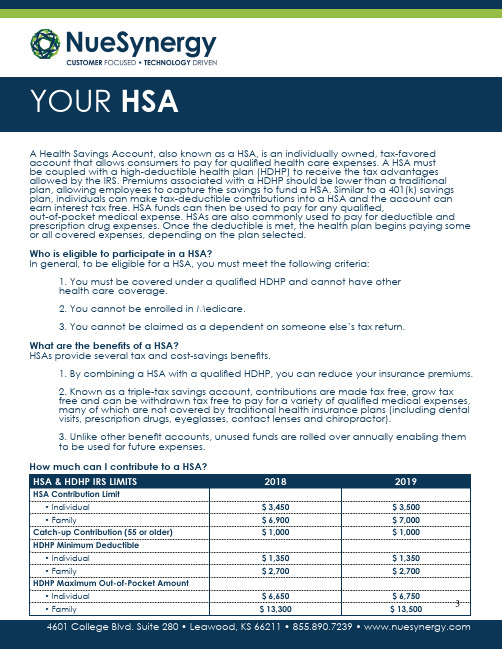
A Health Savings Account, also known as a HSA, is an individually owned, tax-favored account that allows consumers to pay for qualified health care expenses. A HSA mustbe coupled with a high-deductible health plan (HDHP) to receive the tax advantages allowed by the IRS. Premiums associated with a HDHP should be lower than a traditional plan, allowing employees to capture the savings to fund a HSA. Similar to a 401(k) savings plan, individuals can make tax-deductible contributions into a HSA and the account can earn interest tax free. HSA funds can then be used to pay for any qualified,out-of-pocket medical expense. HSAs are also commonly used to pay for deductible and prescription drug expenses. Once the deductible is met, the health plan begins paying some or all covered expenses, depending on the plan selected.Who is eligible to participate in a HSA?In general, to be eligible for a HSA, you must meet the following criteria:1.You must be covered under a qualified HDHP and cannot have otherhealth care coverage.2.You cannot be enrolled in Medicare.3.You cannot be claimed as a dependent on someone else’s tax return.What are the benefits of a HSA?HSAs provide several tax and cost-savings benefits.1.By combining a HSA with a qualified HDHP, you can reduce your insurance premiums.2.Known as a triple-tax savings account, contributions are made tax free, grow taxfree and can be withdrawn tax free to pay for a variety of qualified medical expenses, many of which are not covered by traditional health insurance plans (including dental visits, prescription drugs, eyeglasses, contact lenses and chiropractor).3.Unlike other benefit accounts, unused funds are rolled over annually enabling themto be used for future expenses.TO BEGINSTEP 2 STEP 3STEP 1 • Go to • Click Log in > Member Registration • Start by creating a username • Fill out remaining required fields • Accept terms of use • Click next• Confirm your email address • Confirm your information STEP THREE• Fill out security questions • Click nextSTEP FOUR Accessing your account through the online member portal will enable you to submit claims electronically for faster approval, access balance and claims history, important communications and more.Setting up your account for online access is easy! Just follow the steps below.(For additional help you can download the Registration Guide with step-by-step screen shots at .) Your Employer ID Number is: • You’ve successfully completed NUEMAISTEP 3your account on the Personal DashboardSTEP ONESTEP TWOlocated above your account summaryFEATURE GUIDE1. Account Details: Provides overview of all benefit accounts (FSA, HRA, HSA, etc.)2. Accounts List: Access your account summary, including YTD balance and contributions.3. Contributions: Provides real time current yearcontribution totals, previous year contributions, and IRS limits. Enables you to make a post-tax contribution to your HSA, add other personalaccounts you want to use to fund your HSA, as well as track pending contributions.4. Transactions: All transaction activity on your account detailed with transaction date, type, description, and plan year.5. Investment: Once you have reached minimum balance of $3,500 in your HSA you can establish an investment account with no monthly fee.6. Bill Pay: Here you can either schedule a check STEP TWO2 3 4 5 61NueSynergy is excited to offer you a new way to access your account! By downloading the NueSynergy Mobile app on either your Apple or Android mobile device, you will have a single access point to manage your HSA.TO BEGIN STEP STEP ONESTEP ONE• Access App Store (iPhone) or GooglePlay (Android) • Search for NueSynergy • Select install and accept ‘app permissions’ • Select the app once NueSynergy Mobile is downloadedSTEP TWO• Sign in using the same username and password as for your Participant Portal at (If you have not setup your account on thepartici pant portal, you will need to do so before signing onto NueSynergy Mobile)You can download the NueSynergy Mobile Application by going to either the App Store on your Apple device or GooglePlay on your Android and searching for NueSynergy:The NueSynergy HSA debit card provides a convenient method to pay for out-of-pocket medical expenses for you, your spouse and/or any tax dependents. The card is a convenient benefit, but it is important that you take a moment and understand how it works.Where is the NueSynergy HSA debit card accepted?Participants can use the HSA debit card at qualified merchants to pay for items such as: • Office visit co-pays• Deductible-related expenses• Prescriptions• Dental work (including orthodontia)• Eyeglasses & contactsHow does NueSynergy verify that the HSA debit card is used only for qualified expenses? The IRS-imposed limitations help ensure that the card is used only for qualified expenses. When the card is swiped at a qualified merchant and there is a sufficient balance available in the participant’s HSA, the qualified purchase will be paid directly from the Health Savings Account. The IRS requires participants to keep all receipts for HSA expenses for seven years in the event of a tax audit.All plan communication pertaining to your account activity is provided solely via email at the website. It is important to notify NueSynergy if you change your email address.What are the advantages of using the NueSynergy HSA debit card?Participants who use the card at qualified merchants may pay for eligible expenses without having to reimburse themselves later. Participants can logon to for real-time, online account information including balance, deposits made to date and a list of pending and completed payments.Health Care ExpensesThe IRS allows certain medical, dental, vision, and related services to be reimbursed through an HSA. Below is a partial list of expenses that qualify for HSA reimbursement. OTC medications prescribed by a physician, while not listed below, are still eligible for HSA reimbursement. This list is subject to change and without notice due to new legislation. For a complete list, log on to .Health Care Expenses (cont’d)。
- 1、下载文档前请自行甄别文档内容的完整性,平台不提供额外的编辑、内容补充、找答案等附加服务。
- 2、"仅部分预览"的文档,不可在线预览部分如存在完整性等问题,可反馈申请退款(可完整预览的文档不适用该条件!)。
- 3、如文档侵犯您的权益,请联系客服反馈,我们会尽快为您处理(人工客服工作时间:9:00-18:30)。
R91A-R92A-R93A R512A-R515A R520A-R525A瓦斯燃烧器渐进式/全比例调节安装-使用-维修手册危险、警告和注意事项本手册作为产品的一个必要组成比分,必须交付给用户。
本节中包含的信息是专门为用户和设备安装、维修人员提供的。
用户可以在本手册的第二节中找到关于操作和使用限制的更多信息。
我们强烈建议阅读本手册。
请仔细保存本手册,以备将来参考。
1)总体介绍●设备的安装必须符合现行规定,遵循制造商的指示,并由有资格的人员进行。
●有资格人员是指在民用或工业供暖系统、卫生热水器,特别是由制造商授权的服务中心的部件领域具有技术知识的人员。
●安装不当可能导致人员和动物伤害或财产损失,对此制造商将不会承担责任。
●拆下所有包装材料并检查设备的完整性。
如有任何疑问,请勿使用-请与供应商联系。
包装材料(木箱、钉子、紧固装置、泡沫等)不应留在儿童能接触到的范围,以免造成伤害。
●在进行任何清洗或维修操作前,请将总开关旋转至OFF和/或通过提供的切断装置,将本机与电源断开。
●确保进口和排气格栅畅通。
●在发生故障和/或操作出现异常时,请断开本机。
不要试图修理本机或采取任何直接的行动。
只能联系有资格的人员。
设备应由制造商授权的维修中心专门维修,并提供原始的备件。
不遵守上述指示可能会影响机组的安全性。
为了确保设备的效率和正常运行,必须由有资格的人员按照制造商的指示定期进行维护。
●当决定停止使用该设备时,那些可能构成危险来源的部件应被消除。
●如果设备将被出售或转让给其他用户,或者原用户需要移动并离开设备,请确保说明书始终伴随着设备,以便新所有者和/或安装人员可以使用这些说明。
●对于所有已修改或者有选择安装的单元,应使用原始的配套设备。
●本装置应专门用于其预定用途。
任何其他的使用都应被认为是不适当的,因此是危险的。
对于因安装不当、使用不当和未能遵守制造商提供的说明而造成的损害,根据协议或其他规定,制造商不承担责任。
以下情形的出现会导致爆炸,不完全燃烧气体(比如一氧化碳CO)污染,燃烧,对人、动物、物品造成严重伤害:-未遵守本章节中的警告之一供应2)燃烧器的特别说明●燃烧器应安装在适当的房间内,其通风开口应符合现行法规的要求,并能满足良好的燃烧要求。
●只能使用根据现行法规设计的燃烧器。
●燃烧器应该用于其设计用途。
●在连接燃烧器之前,请确保其额定功率与输送源相同(电力、汽油、或其他燃料)●注意观察热燃烧组件,它们通常靠近火焰和燃料预加热系统,在运行时变热并将在燃烧器停止后仍保持一段时间的热度。
当决定停止使用燃烧器,用户应让有资格的人员执行以下操作:a断开和电源连接的电源线,拆除电源。
b通过手动截止阀断开燃料供应,并将控制手轮从轴上拆卸下来。
特别警告●安装时确保燃烧器已牢固地固定在装置上,以使火焰在装置的火箱内产生。
●在燃烧器启动之前,以及之后至少每年一次,让有资格的人员执行以下操作:a根据装置的热量输入设定燃烧器的燃料流量;b设定助燃空气的流量,使燃烧效率水平至少等于现行法规要求的较低水平;c检查机组运行是否正常燃烧,避免任何有害或污染的未充分燃烧气体超过现行法规允许的限度;d确保控制和安装装置能正常运行;e确保用于排放燃烧产物的排气管道正常运行;f设定和调整操作完成后,确保所有控制装置的机械锁定装置均已适当地紧固;g确保锅炉房有燃烧器使用和维护说明的复印件。
●当燃烧器关闭时,通过RESET按钮重新启动控制箱。
如果发生第二次停机,请致电技术服务,不要试图进一步重置。
●本装置应仅由有资格的人员按照现行规定操作和维修。
3)根据所使用燃料的一般说明3a)电力连接●出于安全考虑,设备必须有效接地并按现行安全规定进行安装。
查,因为制造商不能对由于未能正确接地设备而可能造成的损害承担责任。
●有资格的人员必须对系统进行检查,以确保设备能够达到设备铭牌上标示的最大功率。
特别要注意的是,确保系统电缆的横截面能够满足机组所吸收的功率。
●不允许任何适配器、复式插座和/或延长电缆将本机连接到电源上。
●应根据现行安全规定,通过一个全极性开关连接电源。
●使用任何电力运行的组件意味着要遵守一些基本规则,例如:-不要用身体的潮湿部分和/或赤脚接触设备;-不要拉拽电缆;-除非明确要求,否则不要让设备暴露在天气(雨、日晒等)下;-不允许儿童或者无经验的人员使用设备;●用户不应更换设备输入电缆。
如果电缆损坏,应关闭设备并联系有资格的人员进行更换。
当设备一段时间不使用时,应将给所有电力驱动的组件(如泵、燃烧器等)供电的开关关闭。
3b)用燃气、轻油或其他燃料燃烧一般要求●燃烧器应按现行法规条款由有资格的人员安装;错误安装造成的人和动物的伤害、财产的损失,制造商不承担责任。
●在安装前,建议仔细清洁所有的燃料供应系统管道内部,清除可能影响燃烧器运行的外来物质。
●在燃烧器投入使用前,应由有资格的人员进行以下检查:a燃料供应系统,需密封良好;b燃料流量,确保其基于燃烧器所需的燃烧速率设定;c燃烧器的点火系统,确保其按设计的燃料类型提供;d燃料供应压力,确保其在铭牌标示的范围内;e燃料供应系统,确保其系统尺寸能够满足燃烧器的燃烧速率,且系统按现行法规要求装备了安装和控制装置。
●当燃烧器将要闲置一段时间时,应关闭燃料供应的龙头。
对使用燃气的特殊说明让有资格的人员对安装进行检查,以确保:a燃气输送线和阀门组应符合现行法规和条款;b所有燃气连接应紧固;●不能将燃气管道作为电气设备的接地点。
●不使用时,不要让燃烧器连接,一定要关闭燃气阀门。
●如果用户长时间不在场,应关闭通往燃烧器的燃气输送主阀门。
闻到燃气的预防措施a不要操作电气开关、手机或任何可能产生火花的物品;b立即打开门和窗户,通过产生空气流动来净化房间;c关闭燃气阀门;d联系有资格的人员。
●在安装燃气装置的房间,切勿阻塞通风开口,以避免出现有毒或爆炸性混合物等危险情况。
指令和标准燃气燃烧器欧盟指令-2009/142/EC(燃气指令)-2014/35/UE(低电压指令)-2014/30/UE(电磁兼容性指令)-2006/42/EC(机械指令)统一标准-UNI EN676(气体燃料用自动强制通风燃烧器)-EN55014-1(电磁兼容-家用电器、电动工具和类似器具的要求)-EN60204-1:2006(机械电气系统安全需求)-CEI EN60335-1(家用电器和类似用途电器的安全规范)-CEI EN60335-2-102(家用电器和类似用途电器安全带电气连接的燃气、燃油和固体燃料燃烧器具的特殊要求)-UNI EN ISO12100:2010(机械安全设计通则风险评估与风险减小)轻油燃烧器欧盟指令-2014/35/UE(低电压指令)-2014/30/UE(电磁兼容性指令)-2006/42/EC(机械指令)统一标准-UNI EN267-2011(液体燃料用自动强制通风燃烧器)-EN55014-1(电磁兼容-家用电器、电动工具和类似器具的要求)-EN60204-1:2006(机械电气系统安全需求)-CEI EN60335-1(家用电器和类似用途电器的安全规范)殊要求)-UNI EN ISO12100:2010(机械安全设计通则风险评估与风险减小)国家标准-UNI7824(整体式雾化燃烧器的特性和试验方法)重油燃烧器欧盟指令-2014/35/UE(低电压指令)-2014/30/UE(电磁兼容性指令)-2006/42/EC(机械指令)统一标准-UNI EN267-2011(液体燃料用自动强制通风燃烧器)-EN55014-1(电磁兼容-家用电器、电动工具和类似器具的要求)-EN60204-1:2006(机械电气系统安全需求)-CEI EN60335-1(家用电器和类似用途电器的安全规范)-CEI EN60335-2-102(家用电器和类似用途电器安全带电气连接的燃气、燃油和固体燃料燃烧器具的特殊要求)-UNI EN ISO12100:2010(机械安全设计通则风险评估与风险减小)国家标准-UNI7824(整体式雾化燃烧器的特性和试验方法)燃气-轻油燃烧器欧盟指令-2009/142/EC(燃气指令)-2014/35/UE(低电压指令)-2014/30/UE(电磁兼容性指令)-2006/42/EC(机械指令)统一标准-UNI EN676(气体燃料用自动强制通风燃烧器)-UNI EN267-2011(液体燃料用自动强制通风燃烧器)-EN55014-1(电磁兼容-家用电器、电动工具和类似器具的要求)-EN60204-1:2006(机械电气系统安全需求)-CEI EN60335-1(家用电器和类似用途电器的安全规范)-CEI EN60335-2-102(家用电器和类似用途电器安全带电气连接的燃气、燃油和固体燃料燃烧器具的特殊要求)-UNI EN ISO12100:2010(机械安全设计通则风险评估与风险减小)国家标准燃气-重油燃烧器欧盟指令-2009/142/EC(燃气指令)-2014/35/UE(低电压指令)-2014/30/UE(电磁兼容性指令)-2006/42/EC(机械指令)统一标准-UNI EN676(气体燃料用自动强制通风燃烧器)-UNI EN267-2011(液体燃料用自动强制通风燃烧器)-EN55014-1(电磁兼容-家用电器、电动工具和类似器具的要求)-EN60204-1:2006(机械电气系统安全需求)-CEI EN60335-1(家用电器和类似用途电器的安全规范)-CEI EN60335-2-102(家用电器和类似用途电器安全带电气连接的燃气、燃油和固体燃料燃烧器具的特殊要求)-UNI EN ISO12100:2010(机械安全设计通则风险评估与风险减小)国家标准-UNI7824(整体式雾化燃烧器的特性和试验方法)工业燃烧器欧盟指令-2009/142/EC(燃气指令)-2014/35/UE(低电压指令)-2014/30/UE(电磁兼容性指令)-2006/42/EC(机械指令)统一标准-EN55014-1(电磁兼容-家用电器、电动工具和类似器具的要求)-EN746-2(工业热处理设备第2部分:燃烧和燃料处理系统的安全要求)-UNI EN ISO12100:2010(机械安全设计通则风险评估与风险减小)-EN60204-1:2006(机械电气系统安全需求)-EN60335-2-102(家用电器和类似用途电器安全带电气连接的燃气、燃油和固体燃料燃烧器具的特殊要求)燃烧器铭牌以下信息请参照铭牌:●燃烧器类型和燃烧器型号:与供货商的任何沟通中必须报告●燃烧器ID (序列号):与供货商的任何沟通中必须报告●生产日期(年、月)●关于燃料类型和网络压力的信息符号使用未注意警告可能会对设备或环境造成不可挽回的损害。