NSC891S低频低压解列技术说明书..
电器配件 低压辅助熔断器指南说明书
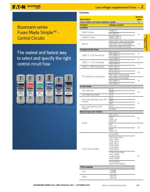
ContentsATC 1A5780ATM1A57781A5779Bussmann seriesFuses Made Simple TM - Control CircuitsFuse holder and block selection guideCatalog pages for the blocks and holders are denoted parenthetically "()" next to their catalog symbol.Cable limitersUH_—————Welder limiters6400068000RM60_ (8-21)————Bolt-on limiters ANNANL 4164 (2-4)4164-FR (2-4)————13/32" x 1-1/2" supplemental fuses BAFFNMFNQKLMKTKBMM603_ (8-6)3743 (8-14)4421 (8-14)4515 (8-14)CCP2-_ (11-2)OPM-1038_ (8-12)OPM-NG_ (8-13)CHM (8-8)NDNF1-WH (8-11)CCPLP†† (30 A) (11-32)HPC-D (8-43)HPD (8-44)HPF (8-43)HPG (8-44)HPM (8-44)HPM-D (8-44)HPS2 (8-45)HPS (8-45)HEB (8-51)HEX (8-53)1A3400_ (3-16)5960 (3-16)13/32" x 1-3/8" supplemental fuses BBS BMM603_ (8-6)—HPS-L (8-45)HEH (8-49)1A3400_ (3-16)5960 (3-16)Pin indication fuses and actuator GBAGLD——HLD (8-43)—1A1119 (3-15)1A1120 (3-15)1A1907 (3-15)1A3398 (3-15)1A4533 (3-15)1A4534 (3-15)5681 (3-16)5682 (3-16) MICFNABMM603_ (8-6)3839†—HPF-C (8-43)—1A3400_ (3-16)5960 (3-16)MIS fuseKAZ actuator2778†2837†2838†———1A3400_ (3-16)5960 (3-16)In-line size rejecting fuses GLQGMQ———HLQ (2-10)—In-line non-rejecting fuses GLRGMFGRF———HLR (2-11)HLR-2A (2-11)—Automotive blade-type fuses ATCATC-_IDFB_-ATC*15600*——ATC-FHID (2-14)HHC (2-14)HHD (2-14)HHF (2-14)HHG (2-14)HHR (2-14)HHS (2-14)1A5600 (2-14)1A5780 (2-14)ATMATM-_IDFB_-ATM*RTMF-_*——ATM-FHID (2-14)HHL (2-14)HHM (2-14)HHU (2-14)1A5778 (2-14)1A5779 (2-14)ATM-LP FB_-ATM*RTMF-_*——HHV (2-14)—ATR micro FB_-ATR*——HH2 (2-14)—MAXMAX-_IDHHX (2-14)MAX-FHID (2-14)* Not shown in this catalog, for details and available configurations, see Automotive and Home center catalog no. 5084.† Not shown in this catalog, see data sheet for details.†† UL 508 Listed disconnect switch, available in 1-, 2- and 3-pole versions.L o w v o l t a g e , s u p p l e m e n t a l f u s e sK 600 V cable limitersCable limiters for protecting 600 V low voltage distribution and service entrance cables against short-circuit currents.Ratings•Volts 600 Vac•IR 200 kA RMS Sym. @ 600 VacAgency information•UL Listed, File E90818, 600 Vac, 200 kA IR on catalog numbers CDA-W, CDB-W, KCD, KCJ, KCM, KCM-B, KCR, KDD, KDF , KDJ, KDM, KDP , KDR, KDU, KEW, KFM, KFT , KHF , KHJ, KHM, KHR Features•Sizes and ratings available to meet many applications* Copper conductors only.** C opper or aluminum conductors.1 UL Listed (File E90818), 600 Vac, 200 kA I.R.2 Available with shrink tube "-V" suffix.3 Available with molded rubber boots.4 Aluminum conductor only.Accessory boots (order separately)Recommended Thomas and Betts crimp tool TBM-14M with die 15506 KDM/15515 KDR for installation.UH 250 V cable limitersCable limiters for protecting 250 V low voltage distribution andservice entrance cables used in residential applications against short-circuit currents.Ratings•Volts Up to 250 Vac•IR 100 kA RMS Sym.T erminals and conductors•Center bolt-to-offset bolt terminals, Cu or Al conductors•Cu or Al conductors are permitted per the listed cable size. Select the catalog number for the conductor size. See data sheet 1042 for dimensions.UHJ-M 3/0250 kcmil UHJ-T 350 kcmil 500 kcmil UHJ-W600 kcmil800 kcmilData sheet no. 104264000 and 68000 600 V welder limitersLimiters for use on welder circuits. Note : welder limiters have special characteristics and are not suitable for use on other circuit types.Ratings•Volts 600 Vac (or less)•IR 200 kA RMS Sym.Features•Current-limiting devices designed specially for use only on welder circuits•Time-current characteristics are designed to hold on the intermittent overloading encountered in welder operation, while providing short-circuit protection to the circuit and equipment68600Class H 60064200Class J 20064300Class J300Recommended fuse blocks, see page 2-2.Data sheet no. 1042Data sheet no. 10454164 and 4164-FR limiter blocksLimiter fuse blocks for ANL and ANN. 4164 is furnished with nylon inserted locknuts and 4164-FR is furnished with standard hex nuts.Dimensions•L 3.38" x W 0.95" x H 1.62"•Studs center-to-center 2.43"Ratings•Volts 125 Vac, 80 Vdc, 32 Vdc (self certified) •Amps 10-800 A•Poles single, stud terminalData sheet no. 213341644164-FRANL/ANN limitersCircuit limiters typically used in fork lifts, marine, aviation and battery charging systems. ANL limiters are fast-acting and ANN limiters are very fast-acting. Both ANL and ANN limiters measure 7/8" x 3-3/16" (22x81mm) with a depth that varies by amp rating.Ratings•Volts•ANL 80 Vdc•ANN 125 Vac, 80 Vdc•Amps•ANL 35-750 A•ANN 10-800 A•IR•ANL 2700 A @ 80 Vdc•ANN 2500 A @ 125 Vac, 2700 A @ 80 VdcAgency information•ANL: UL Recognized, CSA Certified, 35-750 A @ 80 Vdc,IR 2700 A, Guide JFHR2, File E56412, Class 1422-30, File 53787, SAE J1171•ANN: UL Recognized, CSA Certified 35-400 A @ 125 Vac, IR 2500 A and 500 A @ 80 Vdc, IR 2700 A, Guide JFHR2, File E56412, Class 1422-30, File 53787, CE for 35-400 AANN-35ANN-100ANN-250ANN-500ANN-40ANN-125ANN-275ANN-600ANN-50ANN-150ANN-300ANN-700ANN-60ANN-175ANN-325ANN-800ANN-80ANN-200ANN-350Features•Fast-acting sizing for inductive circuits (ANL) •Very fast-acting circuit protection (ANN)•Element viewing window shows limiter status at a glanceFast-acting ANL Very fast-acting ANNData sheet no. 2023 (ANN), 2024 (ANL)BAF fast-acting 13/32" x 1-1/2" supplemental fuseFast-acting, supplemental fuse.Green color code (250 Vac max).For superior protection, Eatonrecommends upgrading toBussmann series Low-Peak ClassCC fuses. See data sheet no. 1023.Ratings1-1/2 to 2-1/2100 A10 kA—X3100 A10 kA X X4 to 10200 A10 kA X X12 to 15750 A10 kA X X20 to 30200 A10 kA——Agency information•UL Listed, Std. 248-14, 250 Vac (3 to 15 A) Guide JDYX,File E19180, CSA Certified, 250 Vac (1/4 to 15 A) Class 1422-01,File 53787BAF-1/2BAF-2BAF-6-1/4BAF-15BAF-6/10BAF-2-1/2BAF-7BAF-20BAF-8/10BAF-3BAF-8BAF-25BAF-1BAF-4BAF-9BAF-30BAF-1-1/2BAF-5BAF-10Features•Green color code for maximum 250 Vac rating•Fiber tube construction with nickel-plated brass endcapsT ypical applications•General purpose circuits•Lighting circuit protection•Meter circuitsRecommended blocks and holders for 13/32" x 1-1/2" fuses, seepage 2-2.KTK fast-acting 13/32" x 1-1/2"supplemental fuseFast-acting supplemental fuse.Black color code (600 Vac max).For superior protection, Eatonrecommends upgrading toBussmann series Low-Peak ClassCC fuses. See data sheet no. 1023.•UL Listed, Std. 248-14, Guide JDYX, File E19180, CSA Certified,C22.2 No. 248.14, Class 1422-01, File 53787, HRC-MISC, RoHScompliant, CEKTK-1/8KTK-1KTK-5KTK-15KTK-2/10KTK-1-1/4KTK-6KTK-20KTK-1/4KTK-1-1/2KTK-7KTK-25KTK-3/10KTK-2KTK-7-1/2KTK-30KTK-4/10KTK-2-1/2KTK-8KTK-1/2KTK-3KTK-9KTK-6/10KTK-3-1/2KTK-10Features•Black color code for 600 Vac rating•Fast-acting for resistive loads•Melamine tube construction with nickel-plated bronze endcapsT ypical applications•Control circuits•Lighting circuit protection•Meter circuitsRecommended blocks and holders for 13/32" x 1-1/2" fuses, seepage 2-2.Data sheet no. 2011 (0-30)Data sheet no. 10112011/65/EUKLM fast-acting 13/32" x 1-1/2" supplemental fuseFast-acting supplemental fuse.Color code black (600 Vac/dcmax). For superior protection,Eaton recommends upgrading toBussmann series Low-Peak ClassCC fuses. See data sheet no. 1023.For protecting PV systems, usePVM 10x30mm PV fuses. See datasheet no. 10121.RatingsElectrical characteristics135%AC opens within 1 hourAgency information•UL Listed, Std. 248-14, Guide JDYX, File E19180, CSA Certified,C22.2 No. 248. 14, Class 1422-01, File 53787, RoHS compliant, CEKLM-1/8KLM-1-1/4KLM-6KLM-20KLM-2/10KLM-1-1/2KLM-7KLM-25KLM-1/4KLM-2KLM-8KLM-30KLM-3/10KLM-2-1/2KLM-9KLM-1/2KLM-3KLM-10KLM-3/4KLM-4KLM-12Features•Color coded for 600 Vac/dc maximum•A full range DC performance fuse•Melamine tube construction with nickel-plated brass endcapsRecommended fuse blocks and holders for 13/32" x 1-1/2" fuses, see page 2-2.FNM time-delay 13/32" x 1-1/2" supplemental fuseTime-delay supplemental fuse.Color code green (250 Vac max).For superior protection, Eatonrecommends upgrading toBussmann series Low-Peak ClassCC fuses. See data sheet no.1023.Ratings1-1/8 to 3-1/2100 A10 kA X X4 to 10200 A10 kA X X12 to 3010 kA—X X Agency information•UL Listed, Std. 248-14, Guide JDYX; File E19180, CSA Certified, Class 1422-01, File 53787, RoHS compliant, CEFNM-1/8FNM-1FNM-2-8/10FNM-7FNM-15/100FNM-1-1/8FNM-3FNM-8FNM-2/10FNM-1-1/4FNM-3-2/10FNM-9FNM-1/4FNM-1-4/10FNM-3-1/2FNM-10FNM-3/10FNM-1-1/2FNM-4FNM-12FNM-4/10FNM-1-6/10FNM-4-1/2FNM-15FNM-1/2FNM-1-8/10FNM-5FNM-20FNM-6/10FNM-2FNM-5-6/10FNM-25FNM-3/4FNM-2-1/4FNM-6FNM-30 Features•Color coded for 250 Vac maximum•Melamine tube construction with nickel-plated brass endcapsT ypical applications•Circuits with high inrush currents (motor/transformer loads)•Supplemental protection for 125 Vac and 250 Vac inductive circuits Recommended fuse blocks and holders for 13/32" x 1-1/2" fuses, seepage 2-2.Data sheet no. 2020Data sheet no. 20282011/65/EU2011/65/EUFNQ time-delay 13/32" x 1-1/2" supplemental fuseTime-delay supplemental fuse.Color code orange (500 Vacmax). For superior protection,Eaton recommends upgrading toBussmann series Limitron FNQ-RClass CC fuses. See data sheet no.1014.RatingsAgency information•UL Listed, Std. 248-14, Guide JDYX, File E19180, CSA Certified,C22.2 No. 248.14, Class 1422-01, File 53787, HRC-MISC, RoHScompliant, CEFNQ-1/8*FNQ-1FNQ-3-1/2FNQ-10FNQ-15/100*FNQ-1-1/8FNQ-4FNQ-12FNQ-3/16FNQ-1-1/4FNQ-4-1/2FNQ-14FNQ-2/10FNQ-1-1/2FNQ-5FNQ-15FNQ-1/4FNQ-1-6/10FNQ-5-6/10FNQ-20FNQ-3/10FNQ-2FNQ-6FNQ-25FNQ-4/10FNQ-2-1/4FNQ-6-1/4FNQ-30FNQ-1/2FNQ-2-1/2FNQ-7FNQ-6/10FNQ-3FNQ-8* Not RoHS compliant.Features•Color coded for 500 Vac maximum•Fiber tube construction with nickel-plated brass endcapsT ypical applications•Motor control transformers•Circuits with in-rush currentsRecommended blocks and holders for 13/32" x 1-1/2" fuses, seepage 2-2.BBS fast-acting 13/32" x 1-3/8" supplemental fuseFast-acting supplemental fuse.Color codes black (600 Vac max1/10 to 6 A), green (250 Vac max7 to 10 A), purple (48 Vac max 12to 30 A). (For superior protection,Eaton recommends upgrading toBussmann series Low-Peak Class7 to 10—10 kA—X X12 to 30*—————* For interrupting rating, contact factory.Agency information•UL Listed, Std. 248-14 (1/10-6 A@600 Vac, 7-10 A@250 Vac), GuideJDYX, File E19180, CSA Certified, C22.2 No. 248.14 (1/10-6 A@600Vac, 7-10 A@250 Vac), Class 1422-01, File 53787, CEBBS-2/10BBS-1BBS-5BBS-20BBS-1/4BBS-1-1/2BBS-6BBS-25BBS-4/10BBS-1-6/10BBS-7BBS-30BBS-1/2BBS-1-8/10BBS-8BBS-6/10BBS-2BBS-10BBS-3/4BBS-3BBS-12Features•Color coded for 600 Vac (black) 250 Vac (green) and 48 Vac (purple)for maximum•Fiber tube construction with nickel-plated brass endcapsT ypical applications•Control circuits•Gaseous vapor fixtures•HID ballasts•Electronic circuits•Hand-held metersRecommended blocks and holders for BBS fuses, see page 2-2.Data sheet no. 1012Data sheet no. 20102011/65/EUGBA/GLD fast-acting 1/4" x 1-1/4" pin-indicating supplemental fuseFast-acting, pin-indicating fuse.Ratings•Volts — see agency information•Amps 1/2-15 A•IR — see agency informationAgency information•UL Listed, Std. 248-14, 0-5 A/125 Vac, 10,000 AIC, Guide JDYX, File E19180•UL Recognized, 6 A/125 Vac, 1000 AIC 8-15 A/50 Vac/dc, 300 AIC Guide JDYX2, File E19180•CSA Certified, 0-5 A/125 Vac, 10,000 AIC Class 1422-01, File 53787•CEGLD-3/4GLD-2GLD-5GLD-12GLD-1GLD-3GLD-6GLD-15 Features•Type GBA has a "red" pin indicator providing visual identification of failed circuits, resulting in faster troubleshooting (reduced circuit downtime)•Type GLD has a plated pin to activate transmitting a electrical signal to indicate the location of opened circuits, resulting in reduced downtimeT ypical applications•Control circuits•Electronic circuitsRecommended fuse blocks/fuse holders for 1/4" x 1-1/4" indicating fuses, see page 2-2.MIC fast-acting 13/32" x 1-1/2" pin-indicating supplemental fuseFast-acting, pin-indicatingsupplemental fuse. Green colorcode (250 Vac max 1 to 15 A), gray(32 Vac max 20 to 30 A).Ratings2 to 3100 A—X—5 to 10200 A—X—15750 A—X—20 to 30—10 kA——Electrical characteristics135% 1 hour max.Agency information•UL Listed, Std. 248-14, 1-15 A, Guide JDYX, File E19180, CEMIC-2MIC-8MIC-20MIC-3MIC-10MIC-25Features•Color coded by maximum voltage rating•Pin indication for visual indication of open fuse condition •Silver-plated pin for positive, electrical signal activation•Fiber tube construction with nickel-plated bronze endcapsT ypical applications•Power electronic circuits in which fuse opening must be quickly apparent•Control circuits•PLC CircuitsRecommended signal block for, 13/32" x 1-1/2" indicating fuses, seepage 2-2.Data sheet no. 10246 Data sheet no. 2012L o w v o l t a g e , s u p p l e m e n t a l f u s e sFNA time-delay 13/32" x 1-1/2" pin-indicating supplemental fusePin-indicating time-delay supplemental fuse. Color coded green (250 Vac max 1/10 to 6 A), blue (125 Vac max 6-1/4 to 15 A) and gray (32 Vac max 20 to 30 A).Ratings1 to 6200 A 10 kA —X X 6-1/4 to 15—10 kA —X X 20 to 30——1 kA——Agency information•UL Listed, 1/10 to 8/10 A @ 125/250 Vac, 1-15 A @ 125 Vac, Guide JDYX, File E19180, CSA Certified, 1/10 to 10 A @ 125 Vac, Class 1422-01, File 53787, CEFNA-1/8FNA-1-1/8FNA-3-2/10FNA-10FNA-15/100FNA-1-1/4FNA-3-1/2FNA-12FNA-2/10FNA-1-4/10FNA-4FNA-15FNA-1/4FNA-1-1/2FNA-4-1/2FNA-20FNA-3/10FNA-1-6/10FNA-5FNA-25FNA-4/10FNA-1-8/10FNA-5-6/10FNA-30FNA-1/2FNA-2FNA-6FNA-6/10FNA-2-1/4FNA-6-1/4FNA-3/4FNA-2-1/2FNA-7FNA-8/10FNA-2-8/10FNA-8Features•Color coded by maximum voltage rating•Pin-indication for visual indication of open fuse condition•Dual-element, time-delay performance permits close sizing on control transformers and relays•Silver-plated pin for positive, electrical signal activation•12 amp and more versions are dual-tube constructionRecommended signal block for 13/32" x 1-1/2" indicating fuses, seepage 2.2.MIS non time-delay 13/32" x 2" pin-indicating supplemental fuse and KAZ non-fuse pin-indicating actuatorMIS is a non time-delay pin-indicating fuse.KAZ is a non-fuse actuator mounted inparallel with fuses having a 50 amp or larger rating to provide blown fuse dropout for shunt-trip fused switches. To order, specify catalog number KAZ .RatingsAmps 1-12 A N/A IR200 kA200 kAMIS fuse electrical characteristics1-5 A 150% 6 min. (max.)6-12 A150%12 min. (max.)MIS-2MIS-4MIS-8MIS-12KAZ agency information•UL Listed, Guide JDVS, File E58836, CEMIS fuse features•Pin indicator provides visual identification of failed circuits,resulting in faster troubleshooting (reduced circuit downtime) •Fuse can be used in circuits rated 600 V or less•High 200 kA interrupting rating for high fault current circuitsMIS fuse typical applications•480 V control circuits•PLC circuitsKAZ actuator features•Convenient means to add open fuse signaling •Actuator can be used in circuits rated 600 V or less•High 200 kA interrupting rating for high fault current circuitsKAZ actuator typical applications•Large, shunt-trip fused switches•Fuse protected circuits rated 50 A or larger with shunt-trip devicesRecommended signal blocks for MIS and KAZ, see page 2-2.Dual-tube construction 12A and upData sheet no. 2029Data sheet no. 2021GLQ fast-acting, size-rejecting supplemental fuseFast-acting, size-rejecting in-line fuse. Match fuse and holder amp rating per catalog number table below.Ratings•Volts 300 Vac (or less) •Amps 1-10 A•IR 10 kAAgency information•UL Listed, Std. 248-14, (Guide JDYX, File E19180), CSA CertifiedC22.2 No. 248.14, (Class 1422-01,File 53787), CE 1 Carrier is UL Recognized, Guide IZLT2, File E14853 and CSA Certified, Class 6225-01, File 47235 10 A, 300 Vac.2 Units can be panel-mounted either in a knockout hole with a separate steel clip (BK/A-104) or in a keyhole punch using separate mounting clip NO.6374 for panels of thickness 0.043"to 0.062" or NO.4909 for thickness 0.030" to 0.042".Note: Do not put tension on line (rear) terminal of fuse holder.Features•In-line, fast-acting circuit protection•Rejection feature prevents overfusingT ypical applications•In-line lighting ballast protectionGMQ time-delay, size-rejecting supplemental fuseTime-delay, size-rejecting in-line fuse. Match fuse and holder amp rating per catalog number table below.Ratings•Volts 300 Vac (or less) •Amps 1/2 to 6-1/4 A•IR 10 kAAgency information•UL Listed, Std. 248-14, (Guide JDYX, File E19180), CSA Certified, (Class 1422-01, File 53787), CE1 Carrier is UL Recognized, Guide IZLT2, File E14853 and CSA Certified, Class 6225-01, File 47235 10 A, 300 Vac.2 Units can be panel-mounted either in a knockout hole with a separate steel clip (BK/A-104) or in a keyhole punch using separate mounting clip NO.6374 for panels of thickness 0.043"to 0.062" or NO.4909 for thickness 0.030" to 0.042"Note: Do not put tension on line (rear) terminal of fuse holder.Features•In-line, fast-acting circuit protection•Rejection feature prevents overfusingT ypical applications•In-line lighting ballast protectionHLQ fuse holders for both GLQ and GMQ fusesData sheet no. 2033Data sheet no. 2030L o w v o l t a g e , s u p p l e m e n t a l f u s e sGLR fast-acting, non size-rejecting supplemental fuseFast-acting, non-rejection, in-line fuse. All fuses use the same HLR or HLR-2A holders.Ratings•Volts 300 Vac (or less) •Amps 3/16-15 A•IR 10 kAAgency information•UL Listed, Std. 248-14, 0-15 A/300 Vac Guide JDYX, File E19180, CSA Certified C22.2, No. 248-14, 0-10 A/300 V Class 1422-01, File 53787, CE1 Carrier is UL Recognized, Guide IZLT2, File E14853 and CSA Certified, Class6225-01, File 47235 12 A, 300 Vac.2 Units can be panel-mounted either in a knockout hole with a separate steel clip (BK/A-104) or in a keyhole punch using separate mounting clip NO.6374 for panels of thickness 0.043"to 0.062" or NO.4909 for thickness 0.030" to 0.042".* For two leads (one each for line and loadside) order HLR-2A, 15 A, 300 V Note: Do not put tension on line (rear) terminal of fuse holder."A" in-line holderAn alternative to the HLR fuse holder is the "A" fuse holder. The A fuse holder comes WITHOUT leads. The customer inserts NO.18 insulated solid copper wire into the lineside receptacle as well as into the load side receptacle. It has the same body dimensions,utilizes the same mounting hole, and takes the same mounting clips as the HLR. The A fuse holder is UL Recognized, 10 A, 300 Vac, Guide IZLT2, File E14853 and CSA Certified, 10 A, 300 Vac, Class 6225-01, File 47235. Order catalog number A.Features•In-line, fast-acting circuit protection.T ypical applications•In-line lighting ballast protectionGMF/GRF time-delay, non size-rejecting supplemental fusesTime-delay, non-rejection, in-line fuse. All fuses use the same HLR or HLR-2A holders.Ratings•Volts 300 Vac (or less) •Amps 3/10-10 A•IR 10 kAAgency information•UL Listed, Std. 248-14 0-10 A, Guide JDYX, File E19180, CSACertified, Class 1422-01, File 53787, CE6225-01, File 47235 12 A, 300 Vac.2 Units can be panel-mounted either in a knockout hole with a separate steel clip (BK/A-104) or in a keyhole punch using separate mounting clip NO.6374 for panels of thickness 0.043"to 0.062" or NO.4909 for thickness 0.030" to 0.042".* For two leads order HLR-2A, 15 A, 300 VNote: Do not put tension on line (rear) terminal of fuse holder."A" in-line holderAn alternative to the HLR fuse holder is the A fuse holder. The A fuse holder comes WITHOUT leads. The customer inserts NO.18 insulated solid copper wire into the line side receptacle as well as into the load side receptacle. It has the same body dimensions,utilizes the same mounting hole, and takes the same mounting clips as the HLR. The A fuse holder is UL Recognized, 10 A, 300 Vac, Guide IZLT2, File E14853 and CSA Certified, 10 A, 300 Vac, Class 6225-01, File 47235. Order catalog number A.Features•In-line, time-delay circuits protectionT ypical applications•In-line lighting ballast protectionHLRfuse holderData sheet no. 2032Data sheet no. 2031HLR-2A fuse holderATM and ATM-LP fast-acting blade fusesFast-acting, color-coded blade fuse available in standard and low-profile versions. Standard version available with indication.Ratings•Volts 32 Vdc •Amps 1-30 A•IR 1000 AAgency information•UL Listed, Guide FHXT, File AU 169 (2-30 A non-indicating ATM)ATM-2—ATM-2LP Gray ATM-3ATM-3ID ATM-3LP Violet ATM-4—ATM-4LP Pink ATM-5ATM-5ID ATM-5LP Tan ATM-7-1/2ATM-7-1/2ID ATM-7-1/2LP Brown ATM-10ATM-10ID ATM-10LP Red ATM-15ATM-15ID ATM-15LP Blue ATM-20ATM-20ID ATM-20LP Y ellow ATM-25ATM-25ID ATM-25LP Clear ATM-30ATM-30IDATM-30LPGreen* Call customer satisfaction for ordering information.Features•Industry standard color coding for easy identification of fuse rating•Indicating versions show blown fuse at a glance, speeds troubleshootingT ypical applications•AutomotiveRecommended blocks and holders for ATM fuses, see page 2-14.ATR fast-acting micro blade fuseFast-acting, color-coded 2-leg micro blade fuse.Ratings•Volts 32 Vdc •Amps 5-30 A•IR 1000 AAgency information•RoHS compliant ATR-7-1/2Brown ATR-25Clear ATR-10Red ATR-30GreenATR-15BlueFeatures•Space-savings size•Industry standard color coding for easy identification of fuse ratingT ypical applications•AutomotiveRecommended holder for ATR fuses, see page 2-14.Low-profileStandardIndicatingData sheet no. 2048 (ATM), 2050 (ATM-LP)2011/65/EUMAX (MAXI) fast-acting blade fuseFast-acting, color-coded, high amp blade fuse. Available with and without indication.Ratings•Volts 32 VdcMAX-25—Gray MAX-30MAX-30ID Green MAX-35—Brown MAX-40MAX-40ID Orange MAX-50MAX-50ID Red MAX-60MAX-60ID Blue MAX-70MAX-70ID Tan MAX-80MAX-80ID Clear —MAX-100IDPurple* Call customer satisfaction for ordering information.Features•Color coded housing for easy identification of fuse rating•Indicating versions show blown fuse at a glance, speeds troubleshootingT ypical applications•AutomotiveRecommended holders for MAX fuses, see page 2-14.ATC fast-acting blade fuseFast-acting, color-coded blade fuse for automotive and control circuit applications.Ratings•Volts 32 Vdc •Amps 1-40 A•IR 1000 AAgency information•UL Recognized, (1-40 A) (Guide JFHR2, File E56412), SAE Standard J1284ATC-2—GrayATC-3ATC-3IDViolet ATC-4—Pink ATC-5ATC-5ID Tan ATC-7-1/2ATC-7-1/2ID Brown ATC-10ATC-10ID Red ATC-15ATC-15ID Blue ATC-20ATC-20ID Y ellow ATC-25ATC-25ID Clear ATC-30ATC-30ID Green ATC-35ATC-35ID Blue-green ATC-40ATC-40IDOrange* Call customer satisfaction for ordering information.Features•Industry standard color coding for easy identification of fuse rating•Indicating versions show blown fuse at a glance, speeds troubleshootingT ypical applications•Automotive•Low voltage control circuitsRecommended blocks and holders for ATC fuses, see page 2-14.StandardIndicatingData sheet no. 2009Data sheet no. 2049In-line fuse holders for ATM, ATC and MAX fusesPCB fuseclips for ATM and ATC fusesATM fuseclips Catalog no. 1A5778•15 A•Nickel-plated brassDimensions — mm (in)Land patternCatalog no. 1A5779•15 A•Nickel-plated brass/glass-filled nylonDimensions — mm (in)ATC fuseclips Catalog no. 1A5600•20 A•Tin-plated cartridge brassDimensions — in (mm)Catalog no. 1A5780•15 A•Nickel-plated brass/glass-filled nylonDimensions — mm (in)Land patternData sheet no. 2131In-line fuse holders for ATM, ATC and MAX blade fuses. Versions available with and without covers and with open fuse indication.Ratings•Volts 32 Vdc•Amps 80% continuous of fuse rating. See catalog numbers tablefor individual holder fuses amp ranges.MAX-FHID Indicator, black w/ cover602x5" #6 red leadwire Fuses must be fully inserted into the holder to provide a solid connection. Poor or improper fuse insertion can result in fuse and holder failure and loss of power and/or circuit protection.Typical in-line blade fuse holders with leadwireseasy ID LED indicating holders available for ATM, ATC and MAX fusesData sheet no. ATM fuses 2128 (HHM, HHL) ATC fuses 2107 (HHC, HHD, HHF , HHG) Max fuses 2129 (HHX)。
891型测振仪使用说明书
国家级新产品891 型测振仪使用说明书中国地震局工程力学研究所中国·哈尔滨目录一.用途及特点二.技术指标三.原理四.使用方法五.仪器的成套性联系我们地址:北京东燕郊经济技术开发区中国地震局工程力学研究所嘉兴市亚太路778号中国科学院园区8号楼1101室电话:8(潘经理)传真:6邮编:314001E-mail:891 型测振仪一、用途及特点891型测振仪是701型测振仪的换代型。
它主要用于测量地面、结构物的脉动或工程振动。
每套测振仪包括891型拾振器六台(四台水平向、两台铅垂向)和891型六线放大器一台。
891型拾振器分为891-1、891-2和891-4三种型号,每种拾振器设有小速度、中速度、大速度和加速度四档。
放大器分891型和891-4型两种,它具有放大,积分,滤波和阻抗变换的功能,891型放大器配接891-1和891-2型拾振器,891-4型放大器配接891-4型拾振器。
用户可根据需要,选取拾振器上微型拨动开关及放大器上参数选择开关相应的档位,即可获取被测点的加速度、速度及位移参量。
本仪器具有体积小、重量轻、使用方便、动态范围大及一机多用的特点,且拾振器簧片不易损坏,不用调节零位。
本仪器可直接与任何记录仪器及数据采集系统配接。
二、技术指标放大倍数:U 0 当参数选择开关置于档1:K=10至5000, 当参数选择开关置于档2:K=1至500,当参数选择开关置于档3:K=5至2500, K I1=30(积分增益) 当参数选择开关置于档4:K=1至500, K I2=10(积分增益)输出负荷 (k Ω):≥1 输入噪声 (μV ):≤1通频带(Hz,-3dB):0.15-100 (参数选择档1和2) 0.35-50 (参数选择档3) 0.2-50 (参数选择档4)电 源:±6~±18V,DC (正负电源差≤0.5V )或220VAC 耗 电:55mA(±12DC 时) 尺 寸:380×240×110mm 重 量:5kg 使用环境:温 度:-10℃~+50℃ 湿 度: ≤85%拾K m 为微型拨动开关。
891型测振仪使用说明书
国家级新产品891 型测振仪使用说明书中国地震局工程力学研究所中国·哈尔滨目录一.用途及特点二.技术指标三.原理四.使用方法五.仪器的成套性891 型测振仪一、用途及特点891型测振仪是701型测振仪的换代型。
它主要用于测量地面、结构物的脉动或工程振动。
每套测振仪包括891型拾振器六台(四台水平向、两台铅垂向)和891型六线放大器一台。
891型拾振器分为891-1、891-2和891-4三种型号,每种拾振器设有小速度、中速度、大速度和加速度四档。
放大器分891型和891-4型两种,它具有放大,积分,滤波和阻抗变换的功能,891型放大器配接891-1和891-2型拾振器,891-4型放大器配接891-4型拾振器。
用户可根据需要,选取拾振器上微型拨动开关及放大器上参数选择开关相应的档位,即可获取被测点的加速度、速度及位移参量。
本仪器具有体积小、重量轻、使用方便、动态范围大及一机多用的特点,且拾振器簧片不易损坏,不用调节零位。
本仪器可直接与任何记录仪器及数据采集系统配接。
二、技术指标891型放大器(包括891型和891-4型)放大倍数:当参数选择开关置于档1:K=10至5000,当参数选择开关置于档2:K=1至500,当参数选择开关置于档3:K=5至2500, K I1=30(积分增益) 当参数选择开关置于档4:K=1至500, K I2=10(积分增益)输入阻抗(kΩ):1000U 0图1 拾振器原理输出负荷 (k Ω):≥1 输入噪声 (μV ):≤1通频带(Hz,-3dB):0.15-100 (参数选择档1和2) 0.35-50 (参数选择档3) 0.2-50 (参数选择档4)电 源:±6~±18V,DC (正负电源差≤0.5V )或220VAC 耗 电:55mA(±12DC 时) 尺 寸:380×240×110mm 重 量:5kg 使用环境:温 度:-10℃~+50℃ 湿 度: ≤85%三、原理(一)拾振器891型拾振器属于动圈往复式拾振器。
NAS916微机低压低频减载装置说明书V2.1

df
a)滑差闭锁:当 dt 大于滑差定值,滑差闭锁元件起动;
b)低电压闭锁:当电压低于定值时,低电压闭锁元件起动;
c)小电流闭锁:当电流小于定值时,小电流闭锁元件起动;
注: fbs:闭锁频率
Ibs: 闭锁电流
fdz:低周频率定值
Udz:低电压闭锁定值
3.2.4 TV 断线报警元件
1) |Ua Ub Uc | 8V
6. 用 户 接 口 … … … … … … … … … … … … … …………………………………………… (4) 6.1 面板及显示„„„„„„„„„„„„„„„„„„„„„„„„„„„„„„ (4) 6.2 按钮„„„„„„„„„„„„„„„„„„„„„„„„„„„„„„„„„ (5) 6.3 口令保护„„„„„„„„„„„„„„„„„„„„„„„„„„„„„„„ (5) 6.4 通信接口„„„„„„„„„„„„„„„„„„„„„„„„„„„„„„„ (5) 6.5 打印接口„„„„„„„„„„„„„„„„„„„„„„„„„„„„„„„ (5)
出口
出口 1
1
0
0
0
0
出口 2
0
1
0
0
0
出口 3
0
0
1
0
0
出口 4
0
0
0
1
0
出口 5
0
0
0
0
1
出口 6
0
0
0
0
0
出口 7
0
0
0
0
0
出口 8
0
0
0
0
0
出口 9
0
0
0
0
0ቤተ መጻሕፍቲ ባይዱ
ER-891说明书
市场营销:开发战略合作伙伴及高效益的代理渠道;共同建设为全国知名品牌
客户服务:建立预防性的客户服务体系,8小时内解决客户问题;
智能卡设备:考勤机、收费机、门禁机等多种IC/ID、CPU/手机卡读写器及智能卡产品;
ER-891机型说明书
第一章品简介
第一节公司简介
依时利科技有限公司成立于1997年,专注于智能卡设备应用及解决方案、集自主研发,生产,销售,客户服务一体化的全国知名IT高科技企业。
依时利科技有限公司于2003年顺利通过ISO2000认证及CCC认证;我们提倡“技术创新`服务为本”的企业理念,并己将依时利建设成一个具有强大竞争力的智能产品服务平台,我们通过与各地具有共同理念和宗旨的销售渠道合作,进行资源整合,共同为客户提供创新、优质的智能卡设备及解决方案。
3如果设置正确,则判断为机具故障。
2.2.2.4常开电锁(通电关门)接法
常开电锁即有电源供应的时候,电锁处于闭门状态,断开电源时,电锁打开。接线图如下:
静态时,6脚悬空,无信号输出,继电器不动作,公共端与常闭端闭合,与常开端开路。电锁无电,处于闭合状态。开门时,6脚对地导通,继电器动作,公共端与常开端闭合,电锁通电打开。直到信号结束。
22.如果设置正确,则判断为机具故障。
2.2.2.5电铃控制接线
常用电铃为AC220V设备,需用继电器转换,接线图如下,然后用接口软件设置电铃时间即可。
不能打铃的检测方法
在接线正确、接头良好的情况下,可按照下列步骤检查:
1.考勤机到达设定时间时用万用表测量8脚(灰色)与6脚(棕色)电压,如果有12V电压则说明后级故障,检查接线。如果没有,进行下一步。
RCS-9658C故障解列装置技术和使用说明书
3.10 逻辑框图 ...................................................................................................................7
3 软件工作原理 ............................................................................................................................................... 4
2.1 机械及环境参数 ........................................................................................................2 2.1.1 机箱结构尺寸................................................................................................................................. 2 2.1.2 工作环境......................................................................................................................................... 2 2.1.3 机械性能......................................................................................................................................... 2
8910C 电能质量分析仪
发货清单
分析仪套件中包括下列物品,请仔细核对,如有不同,请及时联系本公司。
表 1-1 发货清单
序号
名称
数量பைடு நூலகம்
单位
备注
1
电能质量分析仪
1
台
2
电压测试线
5
条
5 色测试线
3
电流钳
把
用户确认量程和数量
4
仪表用电源线
1
根
5
仪表用 0.5A 保险丝
2
只
6
仪表使用说明书
1
份
7
合格证
1
张
8
仪表检测报告
1
份
9
保修单
1
份
第 1 页 共 39 页
电能质量分析仪
第一章 常 规
简 介:
本章主要介绍与8910C电能质量分析仪(以下简称为“分析仪”)有关的许多常规方面的重要内容。 包括: • 注意事项。 • 保证及责任条件。 • 产品合格声明。 • 发货清单: 分析仪套件中应包含的物品清单。 • 联系信息。 • 安全须知: 请先阅读!
测量模式
1. 常态: 当前基本测试数据总览。适用于对电力系统的基本数据的实时监测。 显示趋势----显示连续监测数据的变化情况。 显示记录----显示已经发生并被记录在分析仪内存中的常态数据的相关信息 显示事件----显示已经发生并被记录在分析仪内存中的极值事件的相关信息。 记录开始/记录终止----控制常态记录的开始/结束。 参数设置----与常态数据有关的参数设置。
3. 相量图: 当前测试信号的相量图。适用于对电力系统的基本数据的实时监测。 显示数据----显示当前测试信号的相量数据。
4. 不平衡度: 当前各分相测试数据。适用于对电力系统的不平衡度的实时监测。 显示趋势----显示连续监测数据的变化情况。 显示记录----显示已经发生并被记录在分析仪内存中的不平衡度数据的相关信息。 参数设置----与不平衡度有关的参数设置。 记录开始/记录终止----控制不平衡度记录的开始/结束。
安全稳定控制装置及低频低压解列装置技术性能要求
安全稳定控制装置及低频低压解列装置技术性能要求1 保护配置稳定控制装置要求:配置一套高频切机装置,根据频率、电压事故情况实现过频过压切机、压出力、解列等措施保证系统、机组的安全。
2 装置功能2.1测量装置安装处的电压、电流、频率及电压和频率的变化率。
2.2当电力系统有功功率缺额引起频率下降时,装置可根据频率下降值自动切除部分负荷,使系统有功供求重新平衡;当系统有功功率缺额较大时,装置配有根据df/dt 加速切负荷的功能,以期尽快制止频率下降,防止系统频率崩溃。
2.3当电力系统无功功率不足引起电压下降时,装置可根据电压下降值自动切除部分负荷,确保系统内无功平衡,使电网的电压恢复正常;当电力系统的电压下降较快时,装置配有根据du/dt加速切负荷的功能,以期尽快制止电压下降,防止系统电压崩溃,并使电压恢复到允许的运行范围内。
2.4当地区电网有功功率过剩出现频率上升时,装置可根据频率上升值自动切除部分机组;当有功功率过剩较大时,装置配有根据df/dt 加速跳闸的功能,以期尽快制止频率上升,防止系统频率崩溃。
2.5当电力系统电压升高时,装置可根据电压上升值自动切除部分机组。
2.6装置配有短路故障检测、频率滑差(df/dt)闭锁、电压滑差(du/dt)闭锁、频率异常、频率超限、PT 断线告警、母线失压告警等完善的闭锁功能,可防止由于短路故障、负荷反馈、频率或电压的异常等情况引起的误动作。
2.7装置还可用于低频解列、低压解列、过频解列及过压解列、震荡解列等。
2.8装置需采用全封闭、高阻抗、小功耗继电器,减少装置的功耗和发热,以提高装置的安全性。
2.9装置所有信号在保护屏上有反映,所有信号引出三对接点,用于RTU、中央信号及故障录波,并能与综合自动化装置和保护管理机通讯。
提供2路RS485通讯口和2路以太网接口,采用IEC60870-5-103规约文本。
装置向子站或监控系统提供的信息包括:装置的运行定值及控制字;装置的当前运行定值区;装置的动作信号、动作时间;装置的自检状态,自检出错的类型,出错时刻;装置的当前压板状态;装置的当前模拟量。
9690低频低压解列装置使用说明书
03.事件记录 按“确定”键后,进入菜单,显示如下:
1.保护事件 2.遥信事件
4
9690 低频低压解列装置说明书
3.自检事件
4.事件清除
保护事件:可以记录 64 条保护动作的事件记录,记录编号为 0000~0063,按“确定”
第二部分 保护装置详细说明············································································· 10 一.9690 低频低压解列装置········································································· 10
5
9690 低频低压解列装置说明书
1 开关合位信号 对应开入量 1-14,第四排显示的是光标所在位置的开入量编号和名称。该通道采集到
开入量以后,则对应的位置由数字“0”变成“1”, 注意:开入量的电源为 DC24V,内供的,外面应接入的必须是无源节点。如果开入量
为电源 DC220V 或者 DC110V 的,则电源由外部提供,公共端接-220V,开入量信号接+220V. 开入量电源如果是非内供 24V,则需在订货时说明。
PASSWORD1 PASSWORD2 Address Baud Rate
Parity Address-2 Baud Rate-2 Parity-2 Language
MAC IP Sub Mask Gateway
名称 二次保护电压比例系数 二次保护电流比例系数 二次测量电压比例系数 二次测量电流比例系数 二次测量功率比例系数 接线方式 未定义 滚动显示项目选择 1 滚动显示项目选择 2 一级密码(改定值、投退用) 二级密码(做开出试验用) 装置通讯地址 装置通讯波特率 校验方式 装置通讯地址 装置通讯波特率 校验方式 未定义 MAC 地址 1 IP 地址设置 1 子网掩码 1 网关 1
891-2型拾振器使用说明书V2016公司版
益 4 K12 (1/s)
通道
9
积 参数选择档
分 3 K11 (1/s) 增 参数选择档
益 4 K12 (1/s)
2
3
4
5
6
7
8
10
11
12
13
14
15
16
输入阻抗(KΩ):≥1000 输出负荷(KΩ):≥1 输入噪声(μv):直流供电时≤1;交流供电时≤10。
4
891-2 型拾振器
通 频 带:
通频带选择开关档位 1 2
关于拾振器的保护:拾振器在非使用状态时,均应将“1”档置于“ON”或 把输出端短路,以保护拾振器的运动部件。 2. 放大器使用方法 1) 接通电源
放大器采用 12VDC 供电,配有专用电源适配器,可为放大器提供标准 12V 直
9
891-2 型拾振器
IEM
流电源。
2) 连接线缆
将传感器连接至放大器后面板的“信号输入”端口,将放大器后面板的“信
7
8
9 10
参数
1直
通 10 20 50 100 200 500 1000 2000 4000 5000
2直
通
1 2 5 10 20 50 100 200 400 500
3 积分(KI1=20) 5 10 25 50 100 250 500 1000 2000 2500 4 积分(KI2=4) 1 2 5 10 20 50 100 200 400 500
号输出”端口连接到数据采集仪;
3) 打开电源开关,此时电源开关发出蓝色灯光;
4) 设置放大器各功能开关的位置
根据测量要求,设置放大器前面板的“频带”、“参数”和“放大”三个档
- 1、下载文档前请自行甄别文档内容的完整性,平台不提供额外的编辑、内容补充、找答案等附加服务。
- 2、"仅部分预览"的文档,不可在线预览部分如存在完整性等问题,可反馈申请退款(可完整预览的文档不适用该条件!)。
- 3、如文档侵犯您的权益,请联系客服反馈,我们会尽快为您处理(人工客服工作时间:9:00-18:30)。
NSC 891S数字式低频低压解列装置技术说明书国电南京电力自动化设备总厂2005年6月* 本公司保留对此说明书修改的权利,请注意最新版本资料目次2技术参数 (3)2.1额定参数 (3)2.2主要技术性能 (4)2.3绝缘性能 (4)2.4电磁兼容性能 (5)2.5机械性能 (5)2.6环境条件 (6)4 保护原理 (12)4.5TV断线检测 (13)4.6数据记录 (13)5 定值及整定说明 (14)5.1NSC891S数字式低频低压保护装置整定值清单: (14)5.2NSC891S数字式低频低压保护装置装置软压板清单: (15)1 装置简介本保护装置基本配置为两个CPU插件,由32位微处理器构成的保护及控制单元,该单元配置了大容量的RAM和Flash Memory,具有极强的数据处理、逻辑运算和信息存储能力;另一CPU由总线不出芯片的单片机构成通用的人机接口单元。
两个CPU插件之间相互独立,无依存关系。
各种保护功能及自动化功能均由软件实现。
1)装置特点1:全中文汉化液晶显示,人机界面友善,操作方面。
2:专用测量模块,包括电度计量在内的各种测量及计量精度可达0.5级3:提供累计脉冲电度的接入端4:配置了充足的开关量输入端,方便外部遥信量的接入5:装置自带操作回路及就地操作把手,不需附加其它设备即可直接跳合开关6:设置了高精度的时钟芯片,并配置有GPS硬件对时回路,便于全系统时钟同步7:配备高速以太网络通信接口,并集成了IEC 60870-5-103标准通信规约8:完善的故障录波功能2)完备的保护功能配置表1 本系列产品的型号及功能配置表功能NSC 891S功能NSC 891S低周减载保护√过频保护√低压保护√过压保护√遥信√GPS对时√防误闭锁√远方管理√3)监控功能1:遥信:16路遥信开入量的采集、装置遥信变位、事件遥信等2:遥脉:2路电度脉冲输入3:开出:装置具有13路开出,其中10路由于驱动出口跳闸继电器,3路用于预告警信号驱动。
4:GPS对时功能。
2 技术参数2.1 额定参数2.1.1额定直流电压:220V或110V(订货注明)2.1.2 额定交流数据:a) 相电压3100 V错误!未指定书签。
/c) 交流电流5A或1A(订货注明)d) 额定频率50Hz2.1.3 功率消耗:a) 直流回路正常工作时:不大于20W动作时:不大于30Wb) 交流电压回路每相不大于0.5VAc) 交流电流回路额定电流为5A时:每相不大于1VA额定电流为1A时:每相不大于0.5VA2.1.4 状态量电平:CPU及通信接口模件的输入状态量电平24V(18V~30V)GPS对时脉冲输入电平 24V(18V~30V)各CPU输出状态量(光耦输出)允许电平24V(18V~30V)驱动能力150mA2.2 主要技术性能2.2.1采样回路精确工作范围(10%误差)电压:0.4V~120V电流:0.08In-20In2.2.2 接点容量信号回路接点载流容量 400VA信号回路接点断弧容量 60VA2.2.3各类元件精度电流元件: <±5%电压元件: <±5%时间元件: <±40ms2.2.4整组动作时间(包括继电器固有时间)速动段的固有动作时间:1.2倍整定值时测量,不大于40ms2.2.5模拟量测量回路精度装设专用测量子模件的测控装置:电流、电压:0.2级功率、电度:0.5级2.3 绝缘性能2.3.1绝缘电阻装置的带电部分和非带电部分及外壳之间以及电气上无联系的各电路之间用开路电压500V 的兆欧表测量其绝缘电阻值,正常试验大气条件下,各等级的各回路绝缘电阻不小于50MΩ。
2.3.2介质强度在正常试验大气条件下,装置能承受频率为50Hz,信号输入端子对地电压为500V、其他回路对地电压为2000V,历时1分钟的工频耐压试验而无击穿闪络及元件损坏现象。
试验过程中,任一被试回路施加电压时其余回路等电位互联接地。
2.3.3冲击电压在正常试验大气条件下,装置的电源输入回路、交流输入回路、输出触点回路对地,以及回路之间,能承受1.2/50µs的标准雷电波的短时冲击电压试验,开路试验电压5kV。
2.3.4耐湿热性能装置能承受GB/T 7261第20章规定的湿热试验。
最高试验温度+40℃、最大湿度95%,试验时间为48小时的恒定湿热试验,在试验结束前2小时内根据2.3.1的要求,测量各导电电路对外露非带电金属部分及外壳之间、电气上不联系的各回路之间的绝缘电阻不小于1.5MΩ,介质耐压强度不低于2.3.2规定的介质强度试验电压幅值的75%。
2.4 电磁兼容性能2.4.1静电放电抗干扰度通过GB/T 17626.2-1998标准、静电放电抗干扰4级试验。
2.4.2射频电磁场辐射抗干扰度通过GB/T 17626.3-1998标准、射频电磁场辐射抗干扰度3级试验。
2.4.3电快速瞬变脉冲群抗扰度通过GB/T 17626.4-1998标准、电快速瞬变脉冲群抗扰度4级试验。
2.4.4浪涌(冲击)抗扰度通过GB/T 17626.5-1999标准、浪涌(冲击)抗扰度3级试验。
2.4.5射频场感应的传导骚扰度通过GB/T 17626.6-1998标准、射频场感应的传导骚扰度3级试验2.4.6工频磁场抗扰度通过GB/T 17626.8-1998标准、工频磁场抗扰度5级试验2.4.7脉冲磁场抗扰度通过GB/T 17626.9-1998标准、脉冲磁场抗扰度5级试验。
2.4.8阻尼振荡磁场抗扰度通过GB/T 17626.10-1998标准、阻尼振荡磁场抗扰度5级试验。
2.4.9振荡波抗扰度通过GB/T 17626.12-1998标准、振荡波抗扰度4级试验。
2.4.10辐射发射限值试验通过GB 9254-1998标准、辐射发射限值A类试验。
2.5 机械性能2.5.1振动装置能承受GB/T 7261中16.3规定的严酷等级为I级的振动耐久能力试验。
2.5.2冲击装置能承受GB/T 7261中17.5规定的严酷等级为I级的冲击耐久能力试验。
2.5.3碰撞装置能承受GB/T 7261第18章规定的严酷等级为I级的碰撞试验。
2.6 环境条件a) 环境温度:工作:-20℃~+55℃。
贮存:-25℃~+70℃,在极限值下不施加激励量,装置不出现不可逆的变化,温度恢复后,装置应能正常工作。
b) 相对湿度:最湿月的月平均最大相对湿度为90%,同时该月的月平均最低温度为25 ℃且表面无凝露。
最高温度为+40℃时,平均最大相对湿度不超过50%。
c) 大气压力:(86~106)kPa(相对海拔高度2km以下)。
3 装置硬件本装置在总体设计及各模块设计上均充分考虑了可靠性的要求,在程序执行、信号指示、通信等方面均给予了详尽的考虑。
经试验,在本装置任何端子上实施4kV瞬变干扰脉冲,在装置任何部位实施15kV空间静电放电干扰或8kV接触静电放电干扰,本装置未出现CPU复位,未出现异常信号或异常液晶信息显示,保护不拒动、不误动,远高于国家标准要求。
由于本装置在抗干扰能力上有充分的考虑,故本装置组屏或安装于开关柜上时,不需安装另外的交、直流输入抗干扰模件。
3.1 机箱结构装置采用整面板形式,面板上包括汉化液晶显示器、信号指示灯、操作键盘等,面板靠下部位的运行操作区还设置了用于区分就地与远方操作等功能的切换开关。
安装本装置时,无需其它任何配件,大大简化组屏及现场施工。
本装置的机箱采用全密闭、防水、防尘、抗振动的设计,确保装置安装于条件恶劣的现场时仍具备高可靠性。
3.2 交流插件交流插件包括电压输入和电流输入两个部分,不同型号的装置其电压和电流输入元件的数目不同。
电压输入元件由电压变换器构成,其输入为交流100V时输出为交流3V左右。
线性范围为0.4V-120V。
电流输入元件由电流变换器和并联电阻构成,有三种规格:1) In=5A电流:输入为20In时的输出为5/ 2 ,线性范围为0.04In-20In。
2)In=5A电流:输入为1.1In时的输出为5/ 2 ,线性范围为0.005In-1.1In。
测量级TA。
3) In=1A电流:输入为20A时的输出为5/ 2 ,线性范围为100mA-20A。
3.3 CPU插件CPU插件原理简图如下:图3-1 CPU 模件原理示意图CPU 插件主要由以下几部分构成:1) C PU 系统CPU 系统由微处理器CPU 、RAM 、ROM 、Flash Memory 等构成。
高性能的微处理器CPU (32位),大容量的ROM (512K 字节)、RAM (1M 字节)及Flash Memory (1M 字节),使得该CPU 模件具有极强的数据处理及记录能力,可以实现各种复杂的故障处理方案和记录大量的故障数据。
Flash Memory 中可记录的录波报告为8至50个,可记录的事件数不少于40次。
保护定值等运行配置信息也存入该存储器中,这些信息在装置掉电后均不会丢失。
C 语言编制的保护程序,使程序具有很强的可靠性、可移植性和可维护性。
2) 数据采集系统本装置的数据采集系统由两部分组成。
保护系统采用的数据采集系统由高可靠性的14位精度的A/D 转换器、多路开关及滤波回路组成,最新技术的A/D 转换芯片内部包含了采样保持及同步电路,具有转换速度快、采样偏差小、超小功耗及稳定性好等特点,故本装置的采样回路无可调整元件,也不需要在现场作调整,具备高度的可靠性。
····· ·····CPU 以太网RAMROMFLASHI/O 端子信号 母板信号 出口信号、告警输出RS232至PC 数据采集系统 至MMI 时钟 测量系统运放低通滤波1 低通滤波2 S/H MUXA/D 微处理器 交流变换模件 图3-2 A/D 系统原理示意图测量系统则采用了最新采样技术的测量芯片,测量精度达24位,且无需采用任何软件技术就解决了因频率误差而导致测量误差增大的问题。
测量系统具备测量精度单次调整后自动记忆的功能,在现场无需再作调整。
3)开关量输入及输出部分本装置CPU插件内共设置了16路开入量,其中供外部输入的开关量10路,由装置提供的专用24V电源提供输入电平;另有一路专供GPS对时用,该路输入量可由内部或外部24V 电源提供电平;剩余5路用于监视装置内部状态,例如监测本系统的开出回路,当前断路器位置,控制回路是否断线等。
开出共13路,分为两类,一类是用于驱动出口及信号继电器的,此种开出的+24伏电源都是经过本装置逻辑插件告警继电器常闭接点闭锁的;另一种用于驱动告警、呼唤及信号复归等继电器,其+24伏电源是不经过闭锁的。
