使用VC编程实现DXF文件数据提取
从VCT到DXF数据格式转换_费中强
第29卷第8期 2006年8月合肥工业大学学报(自然科学版)J OU RNAL OF H EFEI UN IV ERSIT Y OF TECHNOLO GYVol.29No.8 Aug.2006 收稿日期:2005208210;修改日期:2005210219作者简介:费中强(1977-),男,安徽肥东人,合肥工业大学硕士生;高 飞(1964-),男,安徽滁州人,合肥工业大学教授,硕士生导师;胡小华(1965-),男,安徽宿县人,合肥市国土资源局信息中心教授级高工,合肥工业大学硕士生导师.从VC T 到DXF 数据格式转换费中强1, 高 飞1, 张克旺2, 胡晓华2(1.合肥工业大学土木建筑工程学院,安徽合肥 230009;2.合肥市国土资源局信息中心,安徽合肥 230001)摘 要:文章通过分析VCT 和DXF 格式文件各自的特点,制作一个包含CASS5.1图形库中所有图形的全集DXF 模板文件,并建立VCT 的要素代码和相应图形的DXF 代码的对应,找到了数据格式转换的方法;用高级编程语言编程,分别读取VCT 中的点、线、面、注记及宗地等要素,在DXF 的实体段中写入相应的DXF 代码,以读写文本文件的方式完成格式转换,从而使VCT 文件可以应用在GIS 系统中。
关键词:GIS ;VCT 格式;DXF 格式;DXF 模板文件;建立对应中图分类号:TP391 文献标识码:A 文章编号:100325060(2006)0821008205T ransform from VCT f iles to D XF f ilesFEI Zhong 2qiang 1, GAO Fei 1, ZHAN G Ke 2wang 2, HU Xiao 2hua2(1.School of Civil Engineering ,Hefei University of Technology ,Hefei 230009,China ;2.The Information Center of Hefei Bureau ofLand Resources ,Hefei 230001,China )Abstract :The characteristics of VCT and DXF files are analyzed ,and t hrough making a DXF module file which includes all t he figures in t he CASS5.1figure warehouse and building a relationship be 2tween t he element codes of VCT files and t he DXF codes of corresponding figures ,a way of t ransfor 2ming VCT files to DXF files is found.Advanced comp uter p rogramming language is adopted ,and t he figure element s such as point s ,lines ,surfaces and annotatio ns are read respectively ,and t hen t he corre 2sponding codes are written into DXF entities ,t hus achieving t he t ransform of file format s by reading and writing .t xt files.Then t he VC T files can be applied in t he geograp hical information system(GIS ).K ey w ords :geograp hical information system (GIS );VC T file ;DXF file ;DXF module file ;building of correspondence AutoCAD 软件包是美国AutoD ES K 公司20世纪80年代初开发的,现已成为国际上流行的微机CAD 软件包,在GIS 中的基础地理数据的采集编制工作中起着重要的作用。
提取dxf的最外围范围框
提取dxf的最外围范围框全文共四篇示例,供读者参考第一篇示例:DXF文件是一种AutoCAD绘图文件的格式,常常会存在需要提取最外围范围框的需求。
这种需求通常出现在需要对文件进行定位、展示或者分析时,提取最外围范围框可以帮助用户更方便地获取文件的整体范围。
今天,我们就来探讨一下如何提取DXF文件的最外围范围框。
我们需要了解DXF文件的结构。
DXF文件是一种文本格式的文件,其包含了CAD绘图的信息,包括图层、线条、圆弧等图形元素。
在DXF文件中,最外围范围框是由文件中所有图形元素的最左下角和最右上角两个点组成的矩形框。
通过提取这两个点的坐标,我们就可以得到文件的最外围范围框。
接下来,我们需要选择一种合适的方法来提取最外围范围框。
一种简单直接的方法是通过编程语言来实现,比如使用Python语言读取DXF文件,解析其中的图形元素并计算出最外围范围框的坐标。
还有一种方法是使用专门的CAD软件,比如AutoCAD或者SolidWorks,这些软件可以直接打开DXF文件并提供相应的功能来获取最外围范围框。
在使用编程语言提取最外围范围框时,我们可以借助开源的库来实现。
比如使用Python的dxfgrabber库可以方便地读取DXF文件并提取其中的图形元素。
接着我们可以利用数学知识来计算出最外围范围框的矩形框,再将其绘制出来或者以其他格式保存。
提取DXF文件的最外围范围框是一项简单但有用的操作。
通过了解DXF文件的结构,选择合适的方法和工具,我们可以方便地提取文件的整体范围,为后续的操作提供便利。
希望本文可以帮助读者更好地理解如何提取DXF文件的最外围范围框,以便在实际工作中更好地应用。
第二篇示例:DXF文件是一种常见的图形文件格式,通常用于存储CAD绘图数据。
在处理DXF文件时,有时我们需要提取文件中的最外围范围框,以便更好地了解文件的整体结构和尺寸。
本文将介绍如何通过使用Python语言和相关库来提取DXF文件的最外围范围框。
读取 DXF 文件

读取DXF 文件以下是一个简单的Visual Basic 6 程序样例,它读取DXF 文件,并且从给定段的给定对象中提取特定代码和值。
' ReadDXF 从DXF 文件中提取指定的代码/值对。
' 此函数需要四个字符串参数、一个有效的DXF' 文件名、一个DXF 段名、该段中对象的' 名称以及由逗号分隔的代码列表。
'Function ReadDXF( _ByVal dxfFile As String, ByVal strSection As String, _ByVal strObject As String, ByVal strCodeList As String)Dim tmpCode, lastObj As StringOpen dxfFile For Input As #1' 获取第一个代码/值对codes = ReadCodes' 遍历整个文件,直到“EOF”行While codes(1) <> "EOF"' 如果组码为“0”,并且值为“SECTION”,则If codes(0) = "0" And codes(1) = "SECTION" Then' 这必须是一个新的段,以便获取下一个' 代码/值对。
codes = ReadCodes()' 如果此段是要获取的段,则If codes(1) = strSection Then' 获取下一个代码/值对,并codes = ReadCodes' 遍历此段,直到“ENDSEC”While codes(1) <> "ENDSEC"' 在某段中,所有的“0”代码都表示' 对象。
如果找到了“0”代码,则存储' 对象名称,供以后使用。
基于VC++的DXF数据文件接口的研究

G3H 文件本质上由代码及关联值对组成’ 代码( 通常称为组码) 表明其后的值的类型’ 使用这 些组码和值对,可以将 G3H 文件组织到由记录组成的区域中,这些记录由组码和数据项目组成’ 在 G3H 文件中,每个组码和值对都各占一行’ 每个段都以一个后跟字符串 LQE<SX( 的组码 * 开始,其后是组码 ) 和表示该段名称的字符串 ( 例如,YQJGQZ) ’ 每个段都由定义其元素的组码和值组成’ 每个段都以一个后跟字符串 Q(GLQE 的组码 * 结束’ G3H 文件完整的结构如下: ! ! [ 收稿日期] )**A B ") B *C! ! ! ! [ 修回日期] )**+ B *) B )D 万方数据 [ 作者简介] 王子茹( "C#A B ) ,女,辽宁铁岭人,教授,博士,从事工程可视化辅助设计、工程图学的研究’
"! G3H 文件基本格式
"N "! G3H 文件 G3HOG/1P40? QR=>10?6 H4&6 ( 图形交换文件) 是一种 JLESS 文本文件,它包含对应的 GTU 文件的
[ +] 全部信息,用它形成图形速度快’ 可以与第三方文件有良好的数据互读 ,如 ,G@1R、 @1:V1W 等都
可以直接读取 G3H 文件,但是作为开发软件的 $E FF 却没有为 G3H 文件设立接口函数’
! 第" 期
王子茹等:基于 #$%% 的 &’( 数据文件接口的研究
・ PW・
)* ( +,-.).)/0&1.1 2 2 3455) { 6/.76- (859, ; } )* ( ( +,-.).)/0 : ; (6//<=0 % 0)>/=* ( ,3?@?AB,8&,C) % ,-.).D9)>/) ; 2 +,-.).)/0 : ; ?=.1E9)>/) { FE=G1E4-E=HI ( +,-.).)/0 : ; J,-.).)/0) ; …… +,-.).)/0 : ; J,-.).)/0 2 FE=G1EC/8EE=H ( +,-.).)/0 : ; J,-.).)/0, +,-.).)/0 : ; ?=.1E9)>/ % KLLMK , FB3& ) ; …… } +,-.).)/0 指向实体结构 ,3?@?@,9 的指针; +,-.).DB/1N/6 : 实体数据头的指针; +,-.).D&1.1 : 将要添加的实体数据结构的指针; ,-.).D9)>/ : 将要添加的实体数据量大小 O PQ PQ M! 图形的绘制 #$ % % 不仅在点定义的时候用的是整数的形式,而且在直线、圆、矩形等绘制的时候所用的参 数全是整数类型,这就决定了将导入数据重绘的时候不能直接用 #$ %% 提供的 R=S/?= ( ) 、 5)-/?= ( ) 等常用的 F&@ 绘图命令O 可以采用两种方法解决这个问题:一是将点的格式转化成像素格式,然 后调用 #$ %% 提供的绘图函数,在视口内绘制图形;二是调用 T+/-F5 动态连接库,利用 T+/-F5 绘 图命令进行绘制O PQ PQ U! 图元信息输出 为了便于直观地了解图形图元信息及二次开发,本程序附带设置了一个图元信息输出接口,使用 者可以根据需要对数据进行查询或输出为 ,VH/E 格式文件O 程序中自带了一个 $,N).E)0. 类,负责对图 元信息的处理O
C编程实现文件复制

C编程实现文件复制文件复制是计算机科学中一个基本的操作,它可以将一个文件的内容复制到另一个文件中。
在C编程语言中,我们可以使用标准库函数来实现文件复制操作。
文件复制的基本步骤如下:1.打开源文件和目标文件:首先,我们需要使用`fopen`函数打开要复制的源文件,指定打开模式为读取模式("r")。
如果文件打开成功,则返回一个文件指针,用于后续的读取操作。
然后,我们使用`fopen`函数打开要复制到的目标文件,指定打开模式为写入模式("w")。
如果文件打开成功,则返回一个文件指针,用于后续的写入操作。
2.读取源文件的内容:使用`fread`函数从源文件中读取一段数据,并将其存储在一个缓冲区中。
`fread`函数需要指定读取的字节数、每个字节的大小和要读取数据的文件指针。
读取成功后,将返回实际读取的字节数。
3.将读取的内容写入目标文件:使用`fwrite`函数将源文件中读取的内容写入到目标文件中。
`fwrite`函数需要指定写入的字节数、每个字节的大小和要写入数据的文件指针。
写入成功后,它将返回实际写入的字节数。
4.关闭文件:当文件复制完成后,我们需要使用`fclose`函数关闭源文件和目标文件,释放相关的资源。
下面是一个简单的示例代码实现文件复制功能:```c#include <stdio.h>#define BUFFER_SIZE 4096int mainFILE *source_file, *destination_file;char buffer[BUFFER_SIZE];size_t bytes_read, bytes_written;//打开源文件和目标文件source_file = fopen("source.txt", "rb");destination_file = fopen("destination.txt", "wb");if (source_file == NULL , destination_file == NULL)printf("文件打开失败\n");return 1;}//读取源文件的内容,并将其写入目标文件while ((bytes_read = fread(buffer, 1, BUFFER_SIZE,source_file)) > 0)bytes_written = fwrite(buffer, 1, bytes_read,destination_file);if (bytes_written != bytes_read)printf("文件写入失败\n");return 1;}}//关闭文件fclose(source_file);fclose(destination_file);printf("文件复制成功\n");return 0;```在上面的示例代码中,我们通过定义了一个缓冲区`buffer`来存储读取和写入的数据。
c读取excel文件内容

c读取excel文件内容在C语言编程中,有时候我们需要读取Excel文件的内容,进行一些数据处理或者分析。
本文将介绍如何在C语言中读取Excel文件的内容,以及如何处理这些数据。
首先,我们需要使用C语言中的一些库来实现对Excel文件的读取。
在C语言中,我们可以使用libxls这个库来读取Excel文件。
这个库提供了一些函数,可以帮助我们打开Excel文件,并逐行读取其中的内容。
接下来,我们需要打开Excel文件,并创建一个workbook对象来表示这个文件。
然后,我们可以使用libxls提供的函数来逐行读取Excel文件中的内容。
通过这些函数,我们可以获取Excel文件中的每一行数据,然后进行处理。
在读取Excel文件的内容之后,我们可能需要对这些数据进行一些处理。
例如,我们可以将这些数据存储到一个数组中,或者进行一些计算操作。
在C语言中,我们可以使用数组来存储这些数据,然后通过循环来对这些数据进行处理。
除了使用libxls这个库之外,我们还可以考虑使用其他一些库来实现对Excel文件的读取。
例如,我们可以使用libxlsxwriter这个库来创建和写入Excel文件,同时也可以使用它来读取Excel文件的内容。
这个库提供了一些函数,可以帮助我们读取Excel文件中的内容,并进行一些处理操作。
总的来说,在C语言中读取Excel文件的内容并不是一件很困难的事情。
通过使用一些库,我们可以很容易地实现对Excel文件的读取,并对其中的内容进行处理。
通过本文的介绍,相信大家对在C语言中读取Excel文件的内容有了更深入的了解。
希望本文能对大家有所帮助。
CADDWGDXF文件C++解析库libdxfrw
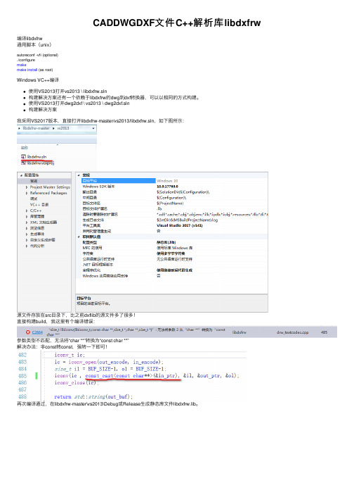
CADDWGDXF⽂件C++解析库libdxfrw编译libdxfrw通⽤脚本(unix)autoreconf -vfi (optional)./configuremakemake install (as root)Windows VC++编译使⽤VS2013打开vs2013 \ libdxfrw.sln构建解决⽅案还有⼀个依赖于libdxfrw的dwg到dxf转换器,可以以相同的⽅式构建。
使⽤VS2013打开dwg2dxf \ vs2013 \ dwg2dxf.sln构建解决⽅案我采⽤VS2017版本,直接打开libdxfrw-master/vs2013/libdxfrw.sln,如下图所⽰:源⽂件存放在src⽬录下,⽐之前dxflib的源⽂件多了很多!直接构建build,我这⾥有个编译错误:参数类型不匹配,⽆法将“char **”转换为“const char **”解决办法:⾮const转const,强转⼀下即可!再次编译通过,在libdxfrw-master\vs2013\Debug或Release⽣成静态库⽂件libdxfrw.lib。
1/******************************************************************************2** dwg2text - Program to extract text from dwg/dxf **3** **4** Copyright (C) 2015 José F. Soriano, rallazz@ **5** **6** This library is free software, licensed under the terms of the GNU **7** General Public License as published by the Free Software Foundation, **8** either version 2 of the License, or (at your option) any later version. **9** You should have received a copy of the GNU General Public License **10** along with this program. If not, see </licenses/>. **11******************************************************************************/1213 #include <iostream>14 #include <fstream>15 #include <sys/stat.h>1617 #include "dx_iface.h"18 #include "dx_data.h"1920void usage(){21 std::cout << "Usage: " << std::endl;22 std::cout << " dwg2text <input>" << std::endl << std::endl;23 std::cout << " input dwg or dxf file to extract text" << std::endl;24 }2526bool extractText(std::string inName){27bool badState = false;28//verify if input file exist29 std::ifstream ifs;30 ifs.open (inName.c_str(), std::ifstream::in);31 badState = ifs.fail();32 ifs.close();33if (badState) {34 std::cout << "Error can't open " << inName << std::endl;35return false;36 }3738 dx_data fData; // 存储cad数据的容器类对象39 dx_iface *input = new dx_iface();40 badState = input->printText( inName, &fData ); // 读取cad⽂件并填充到cad数据容器类对象中,再找出text实体打印出来41if (!badState) {42 std::cout << "Error reading file " << inName << std::endl;43return false;44 }45delete input;4647return badState;48 }4950int main(int argc, char *argv[]) {51bool badState = false;52 std::string outName;53if (argc != 2) {54 usage();55return1;56 }5758 std::string fileName = argv[1];5960if (badState) {61 std::cout << "Bad options." << std::endl;62 usage();63return1;64 }6566bool ok = extractText(fileName);67if (ok)68return0;69else70return1;71 }2、dwg2dxf:将dwg转换为dxf(read/write)1bool convertFile(std::string inName, std::string outName, DRW::Version ver, bool binary, bool overwrite){ 2bool badState = false;3//verify if input file exist4 std::ifstream ifs;5 ifs.open (inName.c_str(), std::ifstream::in);6 badState = ifs.fail();7 ifs.close();8if (badState) {9 std::cout << "Error can't open " << inName << std::endl;10return false;11 }12//verify if output file exist13 std::ifstream ofs;14 ofs.open (outName.c_str(), std::ifstream::in);15 badState = ofs.fail();16 ofs.close();17if (!badState) {18if (!overwrite){19 std::cout << "File " << outName << " already exist, overwrite Y/N ?" << std::endl;20int c = getchar();21if (c == 'Y' || c=='y')22 ;23else {24 std::cout << "Cancelled.";25return false;26 }27 }28 }29//All ok proceed whit conversion30//class to store file read:31 dx_data fData;32//First read a dwg or dxf file33 dx_iface *input = new dx_iface();34 badState = input->fileImport( inName, &fData );35if (!badState) {36 std::cout << "Error reading file " << inName << std::endl;37return false;38 }3940//And write a dxf file41 dx_iface *output = new dx_iface();42 badState = output->fileExport(outName, ver, binary, &fData);43delete input;44delete output;4546return badState;47 }。
DXF文件格式读取(VC例子)

Download demo project - 167 KbIntroductionWhat is DXF?Drawing Interchange Format (DXF) files enable the interchange of drawings between AutoCAD and other programs. DXF files can be either ASCII or binary formats. Because ASCII DXF files are more common than the binary format, CadLib uses ASCII DXF format.What is CadLib?The CadLib is not a Computer Aided Design (CAD) program. It is a tool for creating DXF files that are used in the CAD programs. It consists of two parts. One of them is a Dynamic Link Library to create the DXF file. The other part is the programming interface. It is a class that integrates the cadio.dll functions. It can be used in Microsoft Visual C++ projects. In addition, the cadio.dll can be used in other Win32 programs.Why use CadLib?In some programs, it is needed to create a drawing output for use in other programs such as AutoCad. For example, in a "Building Detail Sheet Generator Program", the program needs to create a drawing output. And the most standard format for communicating drawing data is DXF.DXF file structureThe DXF format is a tagged data representation of all the information contained in a drawing file. Tagged data means that each data element in the file is preceded by an integer number that is called a group code. A group code's value indicates what type of data element follows. This value also indicates the meaning of a data element for a given object (or record) type. Virtually all user-specified information in a drawing file can be represented in DXF format. (from AutoCad's DXF reference)A DXF file consists of some sections. Each section has some drawing data in itself. The CadLib uses the following sections:1.HEADER2.TABLES3.BLOCKS4.ENTITIESThe main reference for DXF file structure that is used for CadLib is the AutoCad's DXF reference. You can find more information about DXF file structure here.ClassesThe classes are interfaces between CadIO.dll and the main program. "Test" has come with CadLib to demonstrate how to generate a DXF file with CDxfFileWrite and CDrawing classes.CDxfFileWrite classCDxfFileWrite gathers all the commands needed to directly create a DXF file. Usage of CDxfFileWrite is as follows:1.Create the DXF fileCollapse | Copy Code2.Begin and end the HEADER section. It's here for compatibility with some CADprograms. Others work without having HEADER section.Collapse | Copy Code3.Begin the TABLES section and put the LAYER, LTYPE, STYLE, DIMSTYLEtable-types as many as you want and then close the sectionCollapse | Copy Code4.Begin ENTITIES section and put entities data (LINE, CIRCLE, SOLID, TEXT,ARC, POINT, DIMLINEAR) and finally close the sectionCollapse | Copy Code5.Close the DXF fileCollapse | Copy CodeCDrawing classCDrawing class has all the commands to create a drawing in memory and save it as a DXF file. Usage of CDrawing is as follows:1.Create the on-memory drawingCollapse | Copy Code2.Create new LAYER, LTYPE, STYLE, DIMSTYLE table-types as many as youwant.Collapse | Copy Code3.Make entities data (LINE, CIRCLE, SOLID, TEXT, ARC, POINT, DIMLINEAR,POLYLINE).Collapse | Copy Code4.Save data to a DXF file.Collapse | Copy Code5.Destroy CDrawing and free allocated memory.Collapse | Copy CodeLoading data from a DXF file1.Create the on-memory drawing.Collapse | Copy Codee LoadDXFFile member function to load DXF file into memory.Collapse | Copy CodeThat's all!ConclusionSince I am a Civil Engineer, I decided to write a program to generate a beam or columns detail sheet without the use of AutoCAD. I have written a program that, with a little data about beam or column, will create the detail sheet automatically. Output of this program is a DXF file and it can be shown in AutoCAD or it can be plotted with it. This program can save the time for drawing the detail sheet withAutoCAD. If you are an AutoCAD operator, you will understand the meaning of words that are used in this article, or if you are a programmer who wants to write a program to create DXF files, first you need a little knowledge about AutoCAD or the drawing programs such as is mentioned above. This code can be useful for programmers who need to create DXF files from their programs. CadLib is not the best one and also there are many commercial software for creating DXF files but they are not open source. Feel free to change the code. Your comments in regards to this article will cause the improvement of CadLib.History∙20 Dec 2002o First release of CadLib∙19 Jan 2003o Some bug fixeso Added Dimension-Line support. It's a combination of other entity commands like "Line" and "Solid"o Added BLOCKS section supporto Added Arc, Point and InsertBlock commands for ENTITIES sectiono Text command has been improved∙11 May 2003o Added CDrawing class to store drawing data in memory and change the data before saving it as a DXF file.∙28 June 2003o Added DXF read capability to CDrawing classo Some bug fixes of CDrawing class when writing data to a DXF file ∙22 Nov 2003 (CadLib Version 2.00)o Added Drawing View capabilityo Added PolyLine command (by Tran duy Dung)o Improved DXF loading speedo Some bug fixes of drawing memory management functions ∙24 Aug 2004 (CadLib Version 2.10)o Added ZoomExtents Functiono Improved Viewing functions to show Dashed Lineso Added "ChangeEntity" & "DeleteEntity" commandso Added Dimension view capabilityo Fixed a bug occures when viewing a rotated blocko Improved viewing of textsLicenseThis article, along with any associated source code and files, is licensed under The Code Project Open License (CPOL)About the Author。
- 1、下载文档前请自行甄别文档内容的完整性,平台不提供额外的编辑、内容补充、找答案等附加服务。
- 2、"仅部分预览"的文档,不可在线预览部分如存在完整性等问题,可反馈申请退款(可完整预览的文档不适用该条件!)。
- 3、如文档侵犯您的权益,请联系客服反馈,我们会尽快为您处理(人工客服工作时间:9:00-18:30)。
使用VC++编程实现DXF文件数据提取
作者:胡胜红
作者单位:湖北经济学院,湖北,武汉,430205
刊名:
福建电脑
英文刊名:FUJIAN COMPUTER
年,卷(期):2006,(11)
被引用次数:7次
1.李晓辉计算机辅助设计与绘图-(AutoCAD2006中文版) 2006
2.詹海生;李广鑫;马志欣基于ACIS的几何造型技术与系统开发 2002
3.孙家广;杨长贵计算机图形学 1994
1.学位论文尚金栓涵闸CAD软件系统的研究1997
该文对国内外普遍采用的AutoCAD绘图软件包的二次开发技术进行了较深入的研究,形成了一套CAD软件开发的实用的理论和方法,并以此理论和方法为指导,开发了一套函闸CAD软件系统.
2.期刊论文吴志林.倪国葳电脑配筋的优越性-科技资讯2009(1)
社会的进步,科技的发展,各行各业的管理都已进入了信息化管理和计算机应用技术的高科技领域.本文论述了结合AntoCAD绘图软件,有效的提高工作效率及合理利用钢筋,降低工程成本的可行性.
3.会议论文廖士源笔画识别法建立Auto CAD绘图汉字库1986
该文提出的笔画识别法,是将点阵汉字转换成绘图笔画汉字行之有效的方法,它成功地把在中国流行的标准线体16×16点阵汉字换成了笔画汉字。
该笔画汉字是用AutoCAD的形定义来描述,能在AutoCAD软件包编辑的图形中插入,并能绘制出带汉字的标准工程图。
采用此法建立的笔画汉字库,不仅字形美观,而且缩短了在PC机上建立笔画汉字库的时间。
该汉字库已配到汉化的AutoCAD绘图软件包CCAD上。
笔画识别法可在其它计算机上,为CAD建立绘图汉字库参考。
(本刊录)
4.学位论文胡友安三峡大型水工闸门结构分析及计算机应用研究--基于MicroStation平台的平面闸门绘图系统的开发1997
MicroStation是一个灵活、通用和高效的绘图软件.该文讨论了MicroStation平台的绘图功能和开发特点,并将该平台与AutoCAD绘图平台进行了比较.阐明了平面闸门计算机辅助绘图系统的基本开发思路、程序结构、数据结构和软件的使用方法等内容.重点介绍了在MicroStation平台上用MDL语言开发"水工金属结构工具图库"和"平面闸门参数化绘图软件"的一些关键技术,例如,程序开发的数据结构,程序结构,图纸表达的示意与夸大,表格数据的函数化和自建的功能函数库等项技术.
1.张国庆DXF文件在激光打标系统的应用研究[期刊论文]-光电技术应用 2010(5)
2.李尚国.陈开岩.司俊鸿.陈辉.宋凯.郝元伟基于VC++的矿井通风系统图DXF文件数据接口研究[期刊论文]-能源技术与管理 2009(3)
3.刘启生.邵东伟.杜云明.张世忠基于DXF文件的数控加工系统的实现研究[期刊论文]-佳木斯大学学报(自然科学版) 2009(4)
4.李芳珍.许伦辉DXF文件格式及其外部接口的研究[期刊论文]-兵工自动化 2008(7)
5.张玉灯.郑涛.毛新生基于AutoCAD的二维建模研究[期刊论文]-水利与建筑工程学报 2008(2)
6.王健.闫立梅型材下料表的参数提取和管理[期刊论文]-计算机辅助工程 2008(3)
7.王子茹.任清波基于VC++的DXF数据文件接口的研究[期刊论文]-厦门理工学院学报 2007(1)
本文链接:/Periodical_fjdn200611117.aspx
授权使用:广东工业大学图书馆(gdgydxtsg),授权号:14ba4b30-d9e9-4578-9cac-9edf00964f0e
下载时间:2011年5月10日。