MSR10科迈中文说明书
雷曼克斯X10中文说明书

录
发送单音脉冲............................................................................... 13 发送可选信令............................................................................... 13 编辑信道....................................................................................... 13 删除信道....................................................................................... 13 快捷功能操作.................................................................................... 14 取消静噪/瞬时取消静噪................................................................. 14 静噪等级设置............................................................................... 14 频率/信道扫描............................................................................ 14 信道扫描....................................................................................... 14 CTCSS/DCS编解码设置........................................................... 14 CTCSS扫描................................................................................. 15 DCS扫描...................................................................................... 15 高、中、低功率选择................................................................... 15 开启/关闭语音压扩功能(降低噪声,提高通话清晰度)......... 15 差频方向及差频频率设置.......................................................... 15 键盘锁定....................................................................................... 16 显示当前电压............................................................................... 16 自动拨号器设置........................................................................... 16 发送自动拨号器中已编辑的信令.............................................. 16 功能设置............................................................................................ 17 步进频率设置............................................................................... 17 添加可选信令............................................................................... 17 选择2TONE信令编码组别................................................................. 18 选择5TONE信令编码组别............................................................ 18 选择DTMF信令编码组别............................................................. 18 信令组合设置............................................................................... 18 高低功率选择............................................................................... 19 宽窄带设置................................................................................... 19 发射功能设置............................................................................... 19
喷雾泵操作手册
Manual No.
SECTION NO. 1 第一部分
OM5277 / OM5275
DRAWINGS and PARTS LISTS INDEX:
图纸及备件单索引
a) Combined Arrangement of Emulsion and Water Pumping Stations 乳化液泵站与喷雾泵站的组合布置
电子保护-水箱
Commissioning of New Pumps
新泵调试
Electrical Protection - Pump
电子保护-泵
Setting and Adjustment of Water Control Valves 水控制阀设置与调节
Starting up System /
Commissioning the Standby Pump
手册目录 手册对照 安全与健康 系统说明 图纸索引 图纸与备件单
SECTION NO. 2 第二部分
‘Open Box’ Inspection
开箱检验
Conveyanபைடு நூலகம்e
运输
Installation of System/Commissioning Tanks 系统安装/水箱调试
Electrical Protection – Tank
THE RMI WATER PUMPING STATION RMI 喷雾泵站
a) The Combined Arrangement of Emulsion and Water pumping Stations, see drawing CL5277, are shown this way as both pumping stations are controlled by one central control panel. RMI 乳化液泵站和喷雾泵站的组合布置请参见图 CL5277,如图所示两套泵站是由一个中心 控制台控制。
达科迈 (DKM) 120传统手动报警器说明书

DKM 120 conventional manual call points handle manual alarm triggering and are used with conventional technology.Functions In the event of an alarm, the glass pane (2) is broken first,then the manual call point (3) is pressed hard.This activates the micro switch for alarm triggering and the indicator LED (4) blinks.A locking mechanism holds the pressed manual call point.The manual call point can be reset with the reset lever (5).The indicator LED (4) goes out.This does not reset the alarm on the fire panel.VariantsThe design of the manual call points for interior areas (form G) and exterior areas (form H) are identical. Three color variants, red, blue, and yellow are available.Detectors for outdoor use (form H) have a cover equipped with a seal.Certifications and ApprovalsVdS - approval number: G 298 061ATEX approval: PTB 01 ATEX 2163XInstallation/Configuration Notes•Manual call points have to be mounted visibly along escape and rescue routes (e.g. exits, passageways,stairwells) and be easily accessible.•An installation height of 1400 mm ±200 mm, measured from the middle of the manual call point to the floor,must be maintained.•Manual call points must be illuminated sufficiently with daylight or another light source (including emergency lighting, if present).•Max. one test detector may be used for primary lines together with automatic detectors. The test detector is connected at the end of the primary line.•Further standards, guidelines and planningrecommendations regarding the installation location etc., should also be taken into consideration (see FireDetection manual).•Regulations of local fire departments must be observed.DKM 120 Manual call point▶Adjustment of the manual call point after alarm triggering ▶Variable labeling possible with foil sets▶Indicator LED for alarm or for inspection evaluation ▶Second contact with connections for panel control ▶Variants for interior and exterior areas2 Installation/configuration notes in accordance with VdS/VDE•The distance between manual call points should notexceed 100 m according to DIN 14 675 or 80 m according to VdS.•In high risk areas, manual call points should be installedat a distance of max. 40 m(VDE 0833 Part 2, Point 7.2.6).•According to VdS, up to 10 manual call points can beconnected to a primary line.Installation•Cables can be inserted surface-mounted or flush-mounted.•Installation in fire hose cabinets is possible in threeways:Pos.Description1Installation depth version 1: min. 37 mm 2Installation depth version 2: 14 mm 3Installation depth version 3: approx. 30 mmPos.Description A "Fire department"B "Break glass"C"Press button hard"Parts IncludedType of deviceQty.ComponentsDKM 120, type G, red 1Manual call point, housing color red DKM 120, type G, blue 1Manual call point, housing color blue DKM 120, type G, yel-low1Manual call point, housing color yellow DKM 120, type H, red 1Manual call point, housing color red, de-tector door with sealDKM 120, type H, blue 1Manual call point, housing color blue, de-tector door with sealDKM 120, type H, yel-low1Manual call point, housing color yellow,detector door with sealDKM 120 test detec-tor, type G, blue 1Manual call point, housing color blue, alu-minum insert plateNoteStandard labeling in German, other labeling possible with universal foil set. The labeling "test detector" is performed using theuniversal labeling field for the upper labeling field.3Technical SpecificationsElectricalOperating voltage19 V DC . . . 30 V DCCurrent consumption Specified by the respective securitysystemMechanicsDimensions (W x H x D)135 x 135 x 36 mmHousing material Plastic (ASA)Colors Red, RAL 3001Blue, RAL 5005Yellow, RAL 1003Weight Approx. 450 gEnvironmental conditionsProtection category as per EN 60529•Type G (indoor area)IP 52•Type H (outdoor area)IP 54Environmental class according toEN 54 T2•Type G (indoor area)II•Type H (outdoor area)IIIPermissible operating temperature•Type G (indoor area)-10 °C . . . +55 °C•Type H (outdoor area)-25 °C . . . +70 °CDKM 120, Type G, redfor triggering the alarm manually using con-ventional technologyManual call point for use in interior areas DKM120-Form-G redDKM 120, Type G, bluefor triggering the alarm manually using con-ventional technologyManual call point for use in interior areas DKM120-Form-G blueDKM 120, Type G, yellowfor triggering the alarm manually using con-ventional technologyManual call point for use in interior areas DKM120 Form G/ yellowDKM 120, Type H, redfor triggering the alarm manually using con-ventional technologyManual call point for use in exterior areas DKM120-Form-H redDKM 120, Type H, bluefor triggering the alarm manually using con-ventional technologyManual call point for use in exterior areas DKM120 Form H/blueDKM 120, Type H, yellowfor triggering the alarm manually using con-ventional technologyManual call point for use in exterior areasDKM120 Form H/yellowDKM 120 Test call point, form G, bluefor triggering the alarm manually using con-ventional technologyManual call point for use in interior areasDKM120-Form-GblueAccessoriesSpare glass pane (PU = 5 pieces)For fire detectors form G, H and KDKM-SPARE-GLASSKey for fire detectors types G and Hmade of red plastic (ASA)FMM-KEY-Form G/HSign with label "Nicht in Betrieb"Metal sign for fire detectors form G or HFMM-SIGNPunched, self-adhesive foil sets (blank), foroperating panel and labeling field10 units, for DM / DKM / SM / SKM, for indi-vidual printingDKM120-LABELMulti-purpose labelling foils for the upperlabel field5 unitsDKM-LABELSEurope, Middle East, Africa:Bosch Security Systems B.V.P.O. Box 800025600 JB Eindhoven, The Netherlands Phone: + 31 40 2577 284Fax: +31 40 2577 330****************************** Americas:Bosch Security Systems, Inc.130 Perinton ParkwayFairport, New York, 14450, USAPhone: +1 800 289 0096Fax: +1 585 223 9180***********************.comAsia-Pacific:Bosch Security Systems Pte Ltd38C Jalan PemimpinSingapore 577180Phone: +65 6319 3450Fax: +65 6319 3499*****************************Represented by© Bosch Security Systems 2006 | Data subject to change without notice T285618571 | Cur: en-US, V3, 26 Sep 2006。
M-Scope便携式安检门说明书
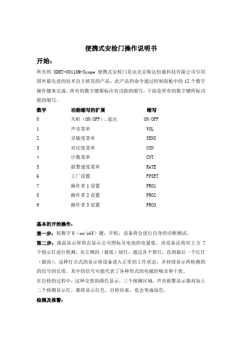
便携式安检门操作说明书开始:所有的SDHT-00110M-Scope便携式安检门是由北京斯达恒通科技有限公司引用国外最先进的技术自主研发的产品,此产品的命令通过控制面板中的12个数字操作键来完成。
所有的数字键都标注有功能的缩写。
下面是所有的数字键所标功能的缩写。
数字功能缩写的扩展缩写0 关机(ON/OFF),退出 ON/OFF1 声音菜单 VOL2 灵敏度菜单 SENS3 对比度菜单 CON4 计数菜单 CNT5 报警速度菜单 RATE6 工厂设置 FPSET7 操作者1设置 PRO18 操作者2设置 PRO29 操作者3设置 PRO3基本的开始操作:第一步:按数字0(on/off)键,开机,设备将会进行自身的诊断测试。
第二步:液晶显示屏将会显示公司图标及电池的电量值。
该设备还将对上方7个指示灯进行检测,从左侧的(最低)绿灯,通过各个黄灯,直到最后一个红灯(最高)。
这种灯点式的显示将设备进入正常的工作状态,并持续显示所检测到的信号的长度。
其中的信号可能代表了各种形式的电磁的噪音和干扰。
在自检的过程中,这种交替的颜色显示,三个探测区域,声音报警显示器再加上二个探测显示灯,都将显示红色。
自检结束,竟会变成绿色。
检测及报警:SDHT-00110M-Scope便携式安检门的主要物体的检测:金属探测报警的过程开始于物体切断安检门通道中的任意一束六束隐形红外光束,尤其是在入口处的三条光束。
必须注意的是,显示灯区的显示灯会持续显示所收到的信号长度,但直到物体进入安全入口并通过感应器的光反应区内。
通过的太快:一旦SDHT-00110M-Scope安检门探测到有物体在通道区,它就会开始检测进入区域的第一束光束和退出区域的第二叔光束的间隔时间。
通过这种通过时间的计量方法,系统会辨别出通过的速度。
如果被测物体超过了SDHT-00110M-Scope安检门所设置的速度限制,显示屏将会显示“Speed Violation”报警音就会响起,区域的显示灯就会变成红色。
micro技术手册(中文显示)
● 相电流输入量 转换;True RMS,采样时间 1.25 毫秒 范围:相 CT 初级电流整定值的 0.1~10 倍 精确度:相 CT 初级电流值的±0.5%
3.1 MMC micro 开关输入------------------------------------------------------------------------------31 3.2 MMC micro 继电器输出---------------------------------------------------------------------------32 七、通讯-------------------------------------------------------------------------------------------------------33 1 通讯连接---------------------------------------------------------------------------------------------------33 2 通讯规约---------------------------------------------------------------------------------------------------33 2.1Modbus RTU 通讯--------------------------------------------------------------------------------------33 2.2Profibus-DP 通讯--------------------------------------------------------------------------------------46 八、典型接线图例--------------------------------------------------------------------------------------- ---51
杀菌机操作手册

4、任何人不准携带任何首饰戒指、手表、领带等带状物品;不准化妆或携带类似化学 物品。
5、不允许穿工作服、雨鞋上卫生间。 6、随时保持工作服工帽鞋的整洁,保持工作现场的卫生,保持维修现场的卫生。
2003-12-01
三、安全防护措施
范围:适用于液体奶生产车间杀菌间。 目的:为了避免意外伤害,执行人员必须有相应的防护措施 执行人:杀菌工、班/组长人员 具体内容:
1. 执行人员必须配制护目镜、橡胶手套及围裙等,并检查其是否有泄漏。 2. 浓酸浓碱等化学物品应在通风干燥的指定地点存放。 3.缓缓地加酸、加碱,防止酸、碱溅到皮肤上,一旦溅上应立即用水冲洗,必要时需 看医生。 4.如人员大面积溅有以上物品,需在喷头下清洗。 5. 若以上物品被人误服用,应立即看医生。 6. 注意日护养中安全事项:
100-1400C
(26)热水压力PI09
3.7-6.5 bar
(28)杀菌水压力PIO8
4.4-7.5bar
(29)高温热水流量FI10
9000-19000L/H
(30)蒸汽压力PI44
6.0-9.0 bar
(31)水压力
3.0-6.0bar
(32)压缩空气压力
≥6.0bar
(33)进Mq 前水压PI66
(19)灌注压力PIO7
0.6-2.5bar
(20)真空度PI12
0.55-0.70bar
(21)热水流量FI66
2300-8000L/H
(2220)03-热12水-01回流温度TT64
80-900C
(23)高温热水温度TI08
132-1600C
(24)杀菌后温度TI09
BESV CF1 快速組裝手冊说明书

快速組裝手冊快速組裝手冊Quick Assembly Guide Quick Assembly GuideBESV CF11BESV CFContents1. 零件說明 (2)1.1主包裝內容 (2)1.2配件包內容 (2)2.組裝流程 (3)2.1組裝豎管及車手把 (3)2.2組裝踏板 (5)2.3組裝坐墊座桿組 (6)3檢查 (7)1.零件說明1.1主包裝內容1.車體組件2.配件包3.座管座墊組1.2配件包內容配件包內含以下配件:1.使用說明書2.充電器3.踏板4.座管鎖鑰匙2.組裝流程2.1組裝豎管及車手把2.1.1旋開豎管螺絲按壓側邊按鈕(a)將豎管打開,將管內螺絲(b)旋鬆。
2.1.2調整豎管高度及方向調整豎管至適當高度,並將頭朝向正前方。
*注意豎管至少需插至標示之最小插入深度 2.1.3鎖緊管內的螺絲ab2.1.4放置車手把調整車手把將標線置中,再旋轉至合適角度。
2.1.5合上豎管將豎管上蓋下壓扣緊。
如豎管過鬆,可調整豎管螺絲加強夾緊力,照片+的方向為緊,-的方向為鬆。
豎管下壓夾緊力:12 ~15kgf。
完成豎管及車手把組裝2.2組裝踏板2.2.1取出配件包內的踏板組2.2.2組裝右腳踏板*注意當中一個踏板的軸上有標示”R”,是為右腳踏板將此標示R的踏板以順時針方向旋轉,裝入右側曲柄的軸孔內並鎖緊。
R2.2.3組裝左腳踏板。
將另一踏板以逆時針方向旋轉,裝入左側曲柄的軸孔內並鎖緊。
請注意必須以逆時針方向旋入。
完成踏板組裝2.3組裝坐墊座桿組2.3.1打開座管束,確認座管轉接座的剖溝與車架剖溝對齊後,將轉接座壓到底。
2.3.2插入座桿*注意座桿嵌入深度,不管任何標示,座桿一定要嵌入至少10公分2.3.3座墊朝前並調整適當高度後,扣緊座管束。
完成坐墊座桿組組裝Min 10cm3檢查3.1檢查輪胎胎壓是否正常3.2檢查煞車, 變速器, 鍊條的作動是否順暢3.3啟動電控檢查功能與電量是否正常. 請參考CF1 使用手冊. 完成BESV CF1 快速組裝。
长虹 ChamSys QuickQ 10 控制台说明书

QuickQ 10 ConsoleGeneral OverviewA.The product shall be a ChamSys QuickQ 10 Console as manufactured by ChamSys Ltd orapproved equal.1.The lighting control console shall be an all-in-one system specifically designed to providecomplete control of stage, studio, and entertainment lighting systems. The console shallbe the ChamSys QuickQ 10 console, as manufactured by ChamSys Ltd.2.The system shall provide control of 1 DMX Universe, or 512 DMX512 addresses on amaximum of 512 control channels or parameters, with control of up to 512 fixturespossible.3. A maximum of 5000cues may be contained in non-volatile electronic flash memory.4.20 multi-function faders shall provide selection and control of 20 fixture intensities, 20fixture group intensities, and 20 single cues.5.Another 3 playback faders shall provide functionality for cue list control – 2 for chases,and 1 for a cue stack.6.The console shall have 1 inbuilt 9.7” colour multi-touch touchscreen. The touchscreenshall provide the primary interface for programming show data, multi-parameter controland system configuration.7. A total of 23 bump buttons shall be provided, used to activate cues, and select ordeselect individual or multiple fixtures.8.The console shall have 2 dedicated hue/saturation encoders for colour control.9.The console shall not require the use of an external monitor for normal use.10.An external monitor port shall be provided to allow connection of an up to HD resolution(1920x1080) monitor for display of the Output & Home (Layout) console windows.11.The console shall provide inbuilt Wi-Fi to connect to an iOS or Android device running aremote-control application to display and control any window independently of theconsole which can used as a secondary display or wireless focus remote.12.Inbuilt Wi-Fi shall feature ‘quick’ connect where a QR code displayed on the consolescreen can be scanned by the remote device (phone or tablet) to connect a remote-control application.13.The console shall be provided with a phone/tablet holder that may affix to the console tosupport the connected remote in a position directly above the in-built console display.14.Console software upgrades shall be made by the user via USB drive. Changing internalcomponents shall not be required to carry out such updates.15.The console shall feature a recovery system, allowing for the console’s operating systemto be restored if required.16.The console shall provide 2 USB ports, allowing show data to be saved for archivalbackups or transfer to other consoles or a personal computer.17.Systems that do not provide the above capabilities shall not be acceptable.Patching and Outputs1.The console shall provide patching facilities for dimmers and multi-parameter devices via aninbuilt library of fixture profiles. The fixture library shall be updated via software-basedupdates.2.The console fixture library shall contain access to over 32,000 fixture files.3.Should any required fixture files not be present in the desk after an update, ChamSys supportshall also be able to create fixture profiles upon request, free of charge.4. A quick search function shall be provided via the Patch window to ensure finding requiredfixtures is a smooth process.5.The console shall support automatic patching of the console and addressing of fixturesconnected using Remote Device Management (RDM) on the local DMX/RDM port.6.The 1 DMX Universe can be output either via the DMX port, or the Ethernet port on theconsole via network protocols of ArtNet or sACN.7.If output of the universe is set to use network protocols, the universe is still also output viathe DMX output connector on the desk.Fixture and Playback Faders1.20 multi-function faders shall be provided on the left side of the console, with 60mmpotentiometers and bump buttons.2.These faders shall provide direct manual control of intensity and selection for up to 20fixtures, 20 fixture groups and 20 single cues. Channel levels can be changed at any time by using the individual channel faders or using the touch screen interface.3.The mode of these faders (fixture, group, or cue) shall be selectable via the FIX, GRP and CUEphysical buttons on the console, to the right of these faders.4.The bump buttons below these faders can be used either to select fixtures and groups, or toactivate stored cues, dependant on the current fixture mode.5.If more than 20 fixtures are patched on the console, individual fixtures will be selectable viathe Layout or Intensity windows in the console software.6.There shall be space above and below these multi-function faders to provide a surface tolegend these faders using adhesive tape.7.RGB LED indicators shall be provided above each individual multi-function fader to providefeedback on the fader mode or the fixture(s) current colour.8. 3 playback faders shall be provided on the right side of the console, with 60mmpotentiometers and bump buttons.9.These faders shall provide space to record and store multiple cues per playback fader, 2faders for chases, and 1 for a cue stack.10.The bump buttons below these faders can be used to activate the stored cues.11.The console shall feature a dedicated Grand Master fader for overall level control.Programming Tools1.The console shall provide a 9.7” colo ur multi-touch touchscreen. The display shall provideaccess to show programming, parameter control and system configuration options.2.The touch interface contains programming windows including Intensity, Position, Colour andBeam, with controls for fixture parameters sorted into these windows for ease of use.3.An inbuilt RGB colour picker shall be accessible via the Colour window for use with colourmixing fixtures, along with inbuilt palettes and gel libraries for quick colour selection.4.The layout view provides a customisable 2D stage layout display. It shall be possible torearrange the graphical position of individual fixtures and groups to closely mimic thepositions of said fixtures in the venue.5.This view shall also provide a visual representation of intensity levels and colours for fixturesand groups laid out here.6.Effects shall be available via each attribute window (Intensity, Position, Colour and Beam) andare customisable via speed, size, and parts controls.7.Tap to time controls shall be available to set the speed of effects and chases.8.It shall be possible to assign multiple effects to fixtures and be stored within a single cue.9.Fixture selection shall be made via the fixture selection faders, Intensity window, or Layoutview.10.Selection of multiple fixtures shall be possible using groups via the fixture selection fadersset to group mode, or via the Layout view.11.Connection to an external, PC-based visualiser system shall be possible via the consoleEthernet port, sending data over the ArtNet or sACN protocols.er levels shall be provided to allow different access levels of control over the console,notably so that programming and configuration of the console can be password protected.13.A choice of 7 languages shall be provided for the console user interface, providing a nativeuser interface in: English, German, Spanish, French, Polish, Romanian, and Dutch.14.Two programming modes shall be provided; Theatre or Live Mode, which shall be userselectable, with the second chase fader acting as a crossfade in Theatre mode. Playback Controls1.Up to 5000 cues may be stored within a single show file on the console. Users shall be ableto save and load multiple show files within the console memory.2.Cues shall be able to be individually recorded and deleted.3.Cues shall be editable via merging in or removing parameters and channels.4.Multiple cues and other items shall also be deleted via the selection menu.5.An Execute view with customisable grid sizes and storage for up to 60 cues shall beaccessible via the console touch screen.6.Cues stored on the Execute grid shall be activated and released via the touch screen and canalso be linked together to work in a solo configuration.Remote Control Protocols1.It shall be possible to remotely activate and release the ten playbacks by use of OSC.2.It shall be possible to synchronise activation of cues in time to audio via Audio Input.3.It shall be possible to remotely activate and release the 3 playbacks by use of UDP Ethernetremote protocol messages.4.Playbacks and Execute window items shall have the ability to be triggered automatically atscheduled times or days without further user interaction.Hardware Connections1.The rear of the console shall provide access to all hardware connections, as listed below.2.12V AC or DC input for external power supply3.DMX512 outputs via 5-pin XLR connector: 1B Type-A connectors: 25.Ethernet connector: 16.HDMI display output: 17.Wi-Fi antenna connection (antenna provided with console): 18. 3.5mm audio jack: 2 (in and out)Physical Specifications1.All operator controls and electronics shall be housed within a single desktop console of aportable size and weight, as below. The console shall be:2.Equal to or less than 525mm (20.7 inches) wide.3.Equal to or less than 350mm (13.8 inches) deep.4.Equal to or less than 106mm (4.2 inches) high.5.Weigh no more than 4.07kg (11.46 lb).6.The console shall be able to be mounted to a standard VESA mount, with the use ofadditional mounting hardware (not supplied).7.The console power shall be 12V AC or DC via an external power unit. The power unit shalloperate with 90-240VAC line voltage, 50 or 60Hz.Included Accessories1.Supplied with the console shall be accessories, as listed below.B desk light: 13.Dust cover: 14.Tablet stand: 15.Wi-Fi antenna: 16.12V power supply: 17.IEC power cable: 1。
- 1、下载文档前请自行甄别文档内容的完整性,平台不提供额外的编辑、内容补充、找答案等附加服务。
- 2、"仅部分预览"的文档,不可在线预览部分如存在完整性等问题,可反馈申请退款(可完整预览的文档不适用该条件!)。
- 3、如文档侵犯您的权益,请联系客服反馈,我们会尽快为您处理(人工客服工作时间:9:00-18:30)。
一、MRS10制屏简介
柴油发电机组控制屏是柴油发电机组控制装置,可实现对机组的启动、运行、停机、紧急停机等操作功能,指示发电机组的三相电压、三相电流、水温、油压、电池电压、运行小时等参数指示,部分型号的控制屏还具备通讯及进行远程监控的能力,为用户实现电信BMS网络监控提供了可能。
同时,它还具有柴油发电机组多种故障保护功能,同时指示出故障类别,为柴油发电机组的可靠运行、方便操作和故障查找等提供了保障和参考。
不同型号的机组控制屏分别可以完成不同的功能,用户可根据不同的使用要求予以选择。
二、MRS10系列控制屏
MRS10系列控制屏除具有基本的发电机组控制屏保护功能外,还具有智能远程“三摇”监控功能及良好的通用性,交流回路与直流回路分开。
该屏采用世界先进的全中文油机主控制器,它具有特大128×64像素的液晶显示屏,能同时显示多行汉字,在结构上十分简单紧凑,功能十分强大,操作非常方便,性价比极高,是各行各业,尤其是通讯机房无人职守后备电站的理想解决方案。
随屏提供标准的RS232计算机通讯接口,具有友好人机界面的全中文上位机软件,用户可以用PC机直接就近连接或通过公用电话网(或电信BMS网络)远程拨号上网监控多台机组。
三、机组控制保护功能
1、手动和自动控制单台机组的启停及加卸负载控制功能;
2、LCD宽屏液晶参数显示:油压、水温、电池电压、运行时间等油机参数,三相相电压、线电流、频率、功率因数、有功功率、无功功率、电度等发电机电参数;
3、发电机组低油压、高水温、超速、超频、速度信号丢失、起动失败、过流、电压过高或过低、、发电机相序错误保护停机;
4、发电机组充电失败、水温高、油压低、电池电压高、电池电压低、传感器故障报警;
5、参数设置授权控制(三级密码保护)
四、操作界面
按键
向前切换控制器工作模式(按OFF—MAN—AUT顺序)
向后切换控制器工作模式(按EST—AUT—MAN—OFF顺序)
消音
故障或报警复位
启动机组
卸载/停机
翻页键(按参数测量页—参数设置页—故障报警页的顺序)
用于在参数设置页内向上选定参数设置项,或向上选定参数测量页或增加选定参数项的设置值
用于在参数设置页内向下选定参数设置项,或向下选定参数测量页或增加选定参数项的设置值
回车键,用于确认参数设置值
发电机电压正常指示灯:如发电机电压正常且满足设置要求,绿灯亮。
机组故障指示灯:如机组出现报警或故障,红灯闪烁。
在按下故障复位键后,红灯亮平光(如故障继续存在)或熄灭(如故障已排除)。
操作方法
怎样改变控制器的运行模式?
用“←”,“→”键选择所需的运行模式OFF—MAN—AUT—TEST
在自动模式下,该键不起作用。
显示菜单
总共有两个大菜单:参数测量页—参数设置页,每一个都有几个小菜单页,可用翻页键选取所需的大菜单,然后用上下键选取小菜单页。
怎样读取测量参数?
可先用翻页键选取所需的参数测量页大菜单,然后用上下键选取其中的一页参数测量页。
发电机输出有功功率表(模拟表表计形式)
发电机运行状态
运行模式
功率因数,带载情况
机组转速
发电机电参数页
发电机频率
发电机三相相电压(三条柱状图)
发电机三相电流(三条柱状图)
传感器测量页
模拟量输入1(油压)的测量值(单条柱状图)
模拟量输入2(水温)的测量值(单条柱状图)
电池电压
发电机功率页
有功功率(每相有功功率及三相总有功功率)
功率因数(每相有功功率及三相总有功功率)
无功功率(每相无功功率及三相总无功功率)
视在功率(每相视在功率及三相总视在功率)
计数页
三相总有功电度数
三相总无功功率电度数
运行小时数
启动次数
下次修期
怎样设置参数?
1、用翻页键选取所需的参数设置页大菜单
2、用上下键选取其中的一页
3、按下确认键
4、用上下键选取其中的一项参数设置项
5、前面有“*”的参数项表示受密码保护,须在密码页内输入正确的密码后方可修改
6、按下确认键
7、用上下键增减参数设置值,当按下上键和下键超过二秒,则参数值加或减越来越快怎样调节液晶显示的背光
当在参数测量页时同时按下确认键及上键或下键可增加亮度或降低亮度。
怎样查看控制器的序列号及软件版本?
当在参数测量页时先按下确认键再按下翻页键,则序列号及软件版本等信息会显示十秒
1、控制器设置的名称(在机组基本参数设置页中可设置)
2、控制器8位数序列号
3、软件版本
4、应用程式
5、名称
怎样查看故障信息
1、可先用翻页键选取所需的参数测量页大菜单,然后用上键翻至报警信息页,反白显示的故障继续存在,没有反白显示的故障已不存在,但尚未确认。
2、按下故障确认键可确认故障,如故障已不存在,则故障信息立即消失;如有新的故障出现,故障报警页会有显示。
五、工作模式
控制器共有四种控制模式:OFF关断—MAN手动—AUT自动,可用模式选择键选择。
OFF关断模式
MAN手动模式
1、开机
1)当机组处于静止状态时,按下START启动键,油门打开,并接通启动马达进行盘车,机组着车后自动退出启动马达,当第一次启动不成功时,经过启动间隔时间后,自动进行第二次启动尝试,如果经过三次启动仍未着车,则发出启动失败信号,并关断油门。
2)机组处于冷却停机状态时,按下START启动键,冷却停机延时取消,机组恢复正常运行(可带载)状态。
3)当发电机电压达到设定值时,发电机电压正常绿灯亮。
2、合机组开关(带载)
3、停机
1)按下停机键,机组首先会自动断开机组输出开关,并开始冷却停机延时,等冷却停机延时过后,机组自动停机。
2)当机组处于冷却停机状态时,按下停机键,冷却停机取消。
机组立即停机。
提示:在手动模式下,即使市电停电,机组也不会自动启动。
AUT自动模式
1、当市电停电时,控制屏首先接到启动信号。
2、经过启动延时后,机组启动,如在机组启动过程中,接到遥停信号,沿时过后机组自
3、如果在一定延时内,机组电压达到设定值,控制屏自动闭合机组开关。
如在延时范围内,机组电压打不到设定值,则机组自动报警停机。
4、如市电电压,频率恢复到正常值,并经市电恢复延时后,则控制屏分开机组开关,机组经冷却延时后自动停机。
提示:在自动模式下,手动按下启动键或停机键不起作用。
重要:在自动模式下,出现停机故障后手动按下故障复位键后机组可能自动启动。
重要:在需拆电池线或断开控制器电源时,应先将控制器置于关断模式,以防下次加电时,由于控制器置于自动模式下,机组突然启动。
六、通讯模式
与PC机直连
MRS10系列控制屏主控制器可直接用标准的RS232通讯线与PC个人电脑直连。
通过MODEM远程拨号联接
MRS10屏主控制器也可通过MODEM远程拨号联接到PC个人电脑。
上位机软件LiteEdit
通过使用上位机软件LiteEdit可以更方便地操作和监视各机组的运行,该软件必须运行在Windows98或更高版本的系统平台上,它具有如下功能:
1、读取/设置参数
2、获取历史记录
3、遥控机组(开机,关机)
4、初始化遥控器
5、安装应用模式的程序
6、设置输入输出量的动作类型
7、直连或通过MODEM登录
报警页说明
MRS10系列屏主控制器提供以下几类报警信息:报警、卸载,有冷却停机延时的停机及立即停机
提示:每一个开关量输入口均可用上位机软件LiteEdit单独设置为一类报警。
每一个报警信息均会在故障报警页显示,最近发生的显示在最上一行。
当有报警故障发生时,控制器仅在报警输出口有输出,并无其它动作,报警故障有:
1、设为报警的开关量输入
2、设为报警的模拟量输入
3、传感器故障
4、电池电压超限
5、发电机相序错
停机故障
当有停机故障发生时,控制器会不经冷却停机延时立即切断燃油,启动马达,预热及开关合闸输出,停机故障有:
1、超速
2、转速过低
3、紧急停机按钮被按下
4、设置为停机故障的开关量输入口
5、设置为紧急停机故障的模拟量输入口
6、发电机开关或市电开关故障
7、发电机电压过高/过低
8、发电机三相电压不平衡
9、发电机电流过高
10、发电机三相电流不平衡。